Downloaded 12 times
![International Research Journal of Engineering and Technology (IRJET) e-ISSN: 2395 -0056
Volume: 04 Issue: 03 | Mar -2017 www.irjet.net p-ISSN: 2395-0072
© 2017, IRJET | Impact Factor value: 5.181 | ISO 9001:2008 Certified Journal | Page 1367
TRAFFIC CLEARANCE FOR EMERGENCY VEHICLES USING PRIORITY
MODE
MR. M. NITHYAKUMAR1, P.ASWIN2, D. BHARATHI SHREE3, M.P.DHARMEESH4,M. KALAIVANI5
1-Assistant Professor, Department of Electronics and Communication Engineering, Jansons Institute of Technology,
Karumathampatti, Coimbatore.
2, 3, 4, 5-Students, Department of Electronics and Communication Engineering, Jansons Institute of Technology,
Karumathampatti, Coimbatore.
---------------------------------------------------------------------***---------------------------------------------------------------------
Abstract: The main motto behind our project is to provide a smart way of controlling traffic light timing during a peak hours and
also to provide smooth flow for the ambulance to reach the hospital in time .We are going to implement a new mode called
“ambulance mode” which would control the traffic lights in the path of the ambulance. This scheme is fully automated thus it
controls the traffic lights, helping to reach the hospital in time. This is not preferred only for ambulance. It is preferrable for other
emergency vehicles such as fire engine.
KEYWORDS: Other names for blue mode: Ambulance mode, Emergency mode, Priority mode.
1.INTRODUCTION:
Traffic congestion and tidal flow management were recognized as major problems. In India as the population is being
increasing day by day the traffic is also increasing with proportionality. So the traffic signals need good coordination
for the smooth flow of traffic during the peak hours .. Moreover road accidents in the city have been incessant and to bar
the loss of life due to the accidents is even more crucial. In this fast moving world we are in a compulsion torushour selfwhich
makes the traffic congestion and accident an inevitable one. In foreign countries, they successfully save human life, because
whenever an ambulance comes they move aside to clear out the route till the ambulance passes through. On the other hand in
INDIA, whenever an ambulance comes it is controlled manually at the traffic junction by a traffic officer.Nowadays all systems
are working automatically. So, we proposed system called “traffic clearance for emergency vehicles using blue mode”.
1.1.MOTIVATION AND RELATED WORK:
In early days, the traffic is controlled manually by police officer. They decide when the vehicle has to cross the road and also
provide importance to the emergency vehicle. Then in Intelligent Traffic Management System, the traffic is controlled
automatically by each lane 120 seconds of green light is set on. Before green light, yellow light flashes for 20 second,signifying
to start your vehicle and be ready to go. The disadvantages of this system is it does not provide timing based on priority
because of that people has to wait for long time even though there is no traffic and also does not recognize and prioritize the
emergency vehicle.[1] They consists of two parts :wireless sensors network(traffic sensor nodes(TSN) groups) and a control
box. In this they collected traffic data with help of sensors and control the traffic.
[2] Describes the concept of traffic clearance in which the time delay (6s) between the switching of signals is based on the
congestion of vehicle. In our project we use 10s for green light to be left ON. If the congestion increases this duration will be](https://image.slidesharecdn.com/irjet-v4i3320-171226064242/85/Traffic-Clearance-for-Emergency-Vehicles-Using-Priority-Mode-1-320.jpg)
![International Research Journal of Engineering and Technology (IRJET) e-ISSN: 2395 -0056
Volume: 04 Issue: 03 | Mar -2017 www.irjet.net p-ISSN: 2395-0072
© 2017, IRJET | Impact Factor value: 5.181 | ISO 9001:2008 Certified Journal | Page 1367
TRAFFIC CLEARANCE FOR EMERGENCY VEHICLES USING PRIORITY
MODE
MR. M. NITHYAKUMAR1, P.ASWIN2, D. BHARATHI SHREE3, M.P.DHARMEESH4,M. KALAIVANI5
1-Assistant Professor, Department of Electronics and Communication Engineering, Jansons Institute of Technology,
Karumathampatti, Coimbatore.
2, 3, 4, 5-Students, Department of Electronics and Communication Engineering, Jansons Institute of Technology,
Karumathampatti, Coimbatore.
---------------------------------------------------------------------***---------------------------------------------------------------------
Abstract: The main motto behind our project is to provide a smart way of controlling traffic light timing during a peak hours and
also to provide smooth flow for the ambulance to reach the hospital in time .We are going to implement a new mode called
“ambulance mode” which would control the traffic lights in the path of the ambulance. This scheme is fully automated thus it
controls the traffic lights, helping to reach the hospital in time. This is not preferred only for ambulance. It is preferrable for other
emergency vehicles such as fire engine.
KEYWORDS: Other names for blue mode: Ambulance mode, Emergency mode, Priority mode.
1.INTRODUCTION:
Traffic congestion and tidal flow management were recognized as major problems. In India as the population is being
increasing day by day the traffic is also increasing with proportionality. So the traffic signals need good coordination
for the smooth flow of traffic during the peak hours .. Moreover road accidents in the city have been incessant and to bar
the loss of life due to the accidents is even more crucial. In this fast moving world we are in a compulsion torushour selfwhich
makes the traffic congestion and accident an inevitable one. In foreign countries, they successfully save human life, because
whenever an ambulance comes they move aside to clear out the route till the ambulance passes through. On the other hand in
INDIA, whenever an ambulance comes it is controlled manually at the traffic junction by a traffic officer.Nowadays all systems
are working automatically. So, we proposed system called “traffic clearance for emergency vehicles using blue mode”.
1.1.MOTIVATION AND RELATED WORK:
In early days, the traffic is controlled manually by police officer. They decide when the vehicle has to cross the road and also
provide importance to the emergency vehicle. Then in Intelligent Traffic Management System, the traffic is controlled
automatically by each lane 120 seconds of green light is set on. Before green light, yellow light flashes for 20 second,signifying
to start your vehicle and be ready to go. The disadvantages of this system is it does not provide timing based on priority
because of that people has to wait for long time even though there is no traffic and also does not recognize and prioritize the
emergency vehicle.[1] They consists of two parts :wireless sensors network(traffic sensor nodes(TSN) groups) and a control
box. In this they collected traffic data with help of sensors and control the traffic.
[2] Describes the concept of traffic clearance in which the time delay (6s) between the switching of signals is based on the
congestion of vehicle. In our project we use 10s for green light to be left ON. If the congestion increases this duration will be](https://image.slidesharecdn.com/irjet-v4i3320-171226064242/75/Traffic-Clearance-for-Emergency-Vehicles-Using-Priority-Mode-1-2048.jpg)
![International Research Journal of Engineering and Technology (IRJET) e-ISSN: 2395 -0056
Volume: 04 Issue: 03 | Mar -2017 www.irjet.net p-ISSN: 2395-0072
© 2017, IRJET | Impact Factor value: 5.181 | ISO 9001:2008 Certified Journal | Page 1368
extended to 20s.[3]Describes about density based traffic clearance. Initially we started this project only for ambulance mode
but we thought of using this concept for normal mode also by using the knowledge of this paper.[4] Portrays area occupied by
the edges of vehicle will be considered to estimate vehicles density using image processing. We makeuseofthisconceptinour
project to clear the traffic congestion in normal mode. Due to insufficient time we have used IR sensor instead. Keeping this
paper as reference we can extend our project by placing camera at junction in four ways. [5]Trafficisclearedusing green wave
system. The green wave is the synchronization of the green phase of traffic signals. The disadvantage of this system is that if
green wave is disturbed the traffic will collapse. [6]Way for ambulance in lane is provided through RFID technology. The
system may not work, if the ambulance needs to take another route for some reasons or if the starting point is not known in
advance. [7] Uses two RFID readers which will identify traffic density on two roads. When emergency vehicle is on lane it turn
traffic signal to green.[8]The images sequences from a camera are analysed using various edge detection and object counting
methods to obtain the most efficient technique to provide smooth flow for the vehicle using” LabVIEW stimulation”.
1.2.CONTRIBUTIONS AND OUTLINE:
Our objective in this paper is to design a system of traffic clearance for emergency vehicle using image processing in matlab
especially by using a new mode called blue mode. In this system, we first control the normal traffic using sensor based density
management [3]. If any emergency situation occur, then the swift movement is important tocontrol thetrafficcongestion.And
by here we introduce a special mode called AMBULANCEMODE, in which there will be an additional indicatorwhichisinblue.
By this the people could know that the ambulance is in its path and try to pave a way for life saver. All these process are
combined and makes the life saver to reach the hospital in time.
2.SYSTEM MODEL:
Our project consists of three main modules which co-ordinates the entire process.
Ambulance module
Control module
Traffic control module
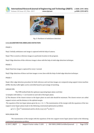
2.1.ALGORITHM FOR ENTIRE PROCESS
1. START
2. Ambulance is on the way to hospital.
3. On reaching the 1 km marking, a camera which is fitted there will take the snap shot of ambulance.
4. Compares the captured image with the reference ambulance image.
5. Case 1: i. If the image matches, a signal will be sent to the traffic light to switch from normal mode to BLUE mode.
ii. This mode continues for 30 seconds and goes to step 6.
Case 2: If the image doesnt matches the traffic light continues to be in normal mode.](https://image.slidesharecdn.com/irjet-v4i3320-171226064242/85/Traffic-Clearance-for-Emergency-Vehicles-Using-Priority-Mode-2-320.jpg)
![International Research Journal of Engineering and Technology (IRJET) e-ISSN: 2395 -0056
Volume: 04 Issue: 03 | Mar -2017 www.irjet.net p-ISSN: 2395-0072
© 2017, IRJET | Impact Factor value: 5.181 | ISO 9001:2008 Certified Journal | Page 1371
w is minimized and for all {( )}, ( +b) - and ξ≥
Kernel functions processes dual maximum margin problem in feature space using linear classification. The resulting
model is then a linear model in feature space and a non-linear model in input space.
Linear kernel: k(
Polynomial kernel :
k( ,γ>0
RBF kernel:
k( =exp(-γ││ ,γ>0
SIGMOID KERNEL:
k( =tanh ,γ>0
%match = number of pixels matched successfully / total number of pixels.
On the detection of ambulance arrival a signal *1 is programmed to send via Zigbee module which is fittedat1Kmmarking.On
receiving this signal by another Zigbee module which is at traffic light will switch the signal from normal mode to ambulance
mode. After a time delay a signal *2 will be send to return normal mode[3].
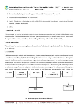
2.4TRAFFIC CONTROL MODULE
This unit will control the traffic congestion in normal mode as well as in blue mode.
Fig -4: Block diagram of traffic signal
ZIGBEE LEVEL
CONVERTER
PIC 16F877A
TRAFFIC
LIGHT
TRAFFIC
DENSITY
SENSOR
AMPLIFIER](https://image.slidesharecdn.com/irjet-v4i3320-171226064242/85/Traffic-Clearance-for-Emergency-Vehicles-Using-Priority-Mode-5-320.jpg)
![International Research Journal of Engineering and Technology (IRJET) e-ISSN: 2395 -0056
Volume: 04 Issue: 03 | Mar -2017 www.irjet.net p-ISSN: 2395-0072
© 2017, IRJET | Impact Factor value: 5.181 | ISO 9001:2008 Certified Journal | Page 1373
elseif (t==medium)
{
Time = 20 sec;
}
elseif (t==high)
{
Time=30 sec;
}}
i = checking whether referred images matched with captured images
t = number of vehicle.
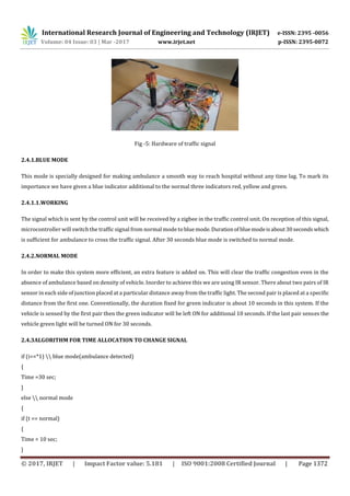
3. FUTURE IMPLEMENTATION
In our project we have used only one camera at 1km marking. We have implemented this in only one side of the junction. This
project can be extended further using camera fitted at 1km marking of eachside.Wecanalsofixanothercamera atthejunction
to detect the departure of ambulance instead of using 30 seconds delay.IR sensor can be replaced by this camera in normal
mode.
4.REAL TIME IMPLEMENTATION:
We have used zigbee module cc250 which cover area of 50metres in real time implementation we can use the following:
1) Xbee pro which cover area of 5km.
2) Using global system for mobile communication (GSM).
3) Using internet of things (IOT).
In our system we have used sobel operator for edge detectionbecauseofitssimplicity, detectionofedgesandtheirorientations
but this is sensitive to noise so in real time implementation we can use canny edge detection algorithm.
5. REFERENCE:
[1] KHALIL M. YOUSEF, JAMAL N. AL-KARAKI, “Intelligent Traffic Light Flow Control System Using Wireless Sensors
Networks”, JOURNAL OF INFORMATION SCIENCE AND ENGINEERING 26, 753-768 (2010).
[2] WM El-Medany 1, MR Hussain,” FPGA-Based Advanced Real Traffic Light Controller System Design” IEEE International
Workshop on Intelligent Data Acquisition and Advanced Computing Systems: Technology and Applications 6-8 September
2007, Dortmund, Germany1-4244-1348-6/07/$25.00 ©2007 IEEE 100.
[3]Minal K. Avzekar1, Amruta Moon,” Adaptive Traffic Signal Control with VANET” International Journal of Scientific
Engineering and Research (IJSER) Volume 2 Issue 3, March 2014.
[4] Mohammad ShahabUddin, Ayon Kumar Das, Md. Abu Taleb,” real-time area based traffic density estimation by image
processing for traffic signal control system:bangladeshperspective”2ndInt'l Conf.onElectrical EngineeringandInformation&
Communication Technology (ICEEICT) 2015
Jahangirnagar University, Dhaka-1342, Bangladesh, 21-23 May 2015.](https://image.slidesharecdn.com/irjet-v4i3320-171226064242/85/Traffic-Clearance-for-Emergency-Vehicles-Using-Priority-Mode-7-320.jpg)
![International Research Journal of Engineering and Technology (IRJET) e-ISSN: 2395 -0056
Volume: 04 Issue: 03 | Mar -2017 www.irjet.net p-ISSN: 2395-0072
© 2017, IRJET | Impact Factor value: 5.181 | ISO 9001:2008 Certified Journal | Page 1374
[5]A. K. Mittal and D. Bhandari, “A novel approach to implement green wave system and detection of stolen vehicles,” in Proc.
IEEE 3rd Int.Adv.Comput., Feb. 2013, pp. 1055–1059.
[6]R. Hegde, R. R. Sali, and M. S. Indira, “RFID and GPS based automatic lane clearance system for ambulance,” Int. J. Adv. Elect.
Electron.Eng., vol. 2, no. 3, pp. 102–107, 2013.
[7]Sarika B. Kale, and Gajanan P. Dhok” Design of Intelligent Ambulance and Traffic Control”, International Journal of
Innovative Technology and Exploring Engineering (IJITEE) ISSN: 2278-3075, Volume-2, Issue-5, April 2013.
[8]Veeravenkatesh, Nazneensyed ,” smart traffic control system for emergency vehicle clearance” International Journal of
Innovative Research in Computer and Communication Engineering –Vol.3, Issue 8, August 2015.](https://image.slidesharecdn.com/irjet-v4i3320-171226064242/85/Traffic-Clearance-for-Emergency-Vehicles-Using-Priority-Mode-8-320.jpg)

This document describes a system to provide priority traffic control for emergency vehicles using a "blue mode." The system uses image processing to detect an ambulance 1 km from an intersection. If detected, a signal is sent to switch the traffic lights from normal mode to blue mode for 30 seconds. In normal mode, IR sensors monitor traffic density and extend green lights accordingly. The goal is to help ambulances reach the hospital more quickly in an automated way. Future enhancements could include additional cameras at intersections and using more advanced technologies like XBee or GSM for wireless communication over longer distances.


