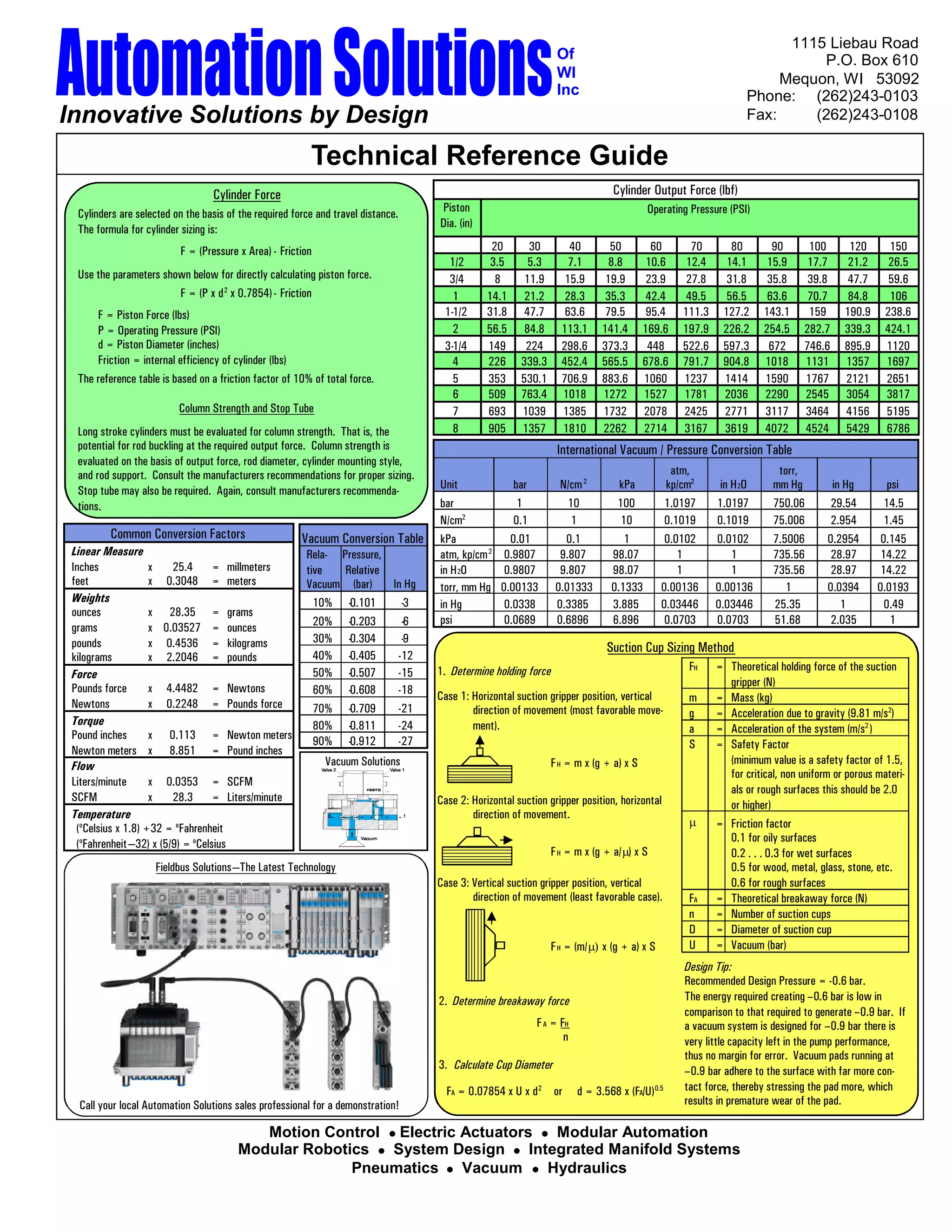
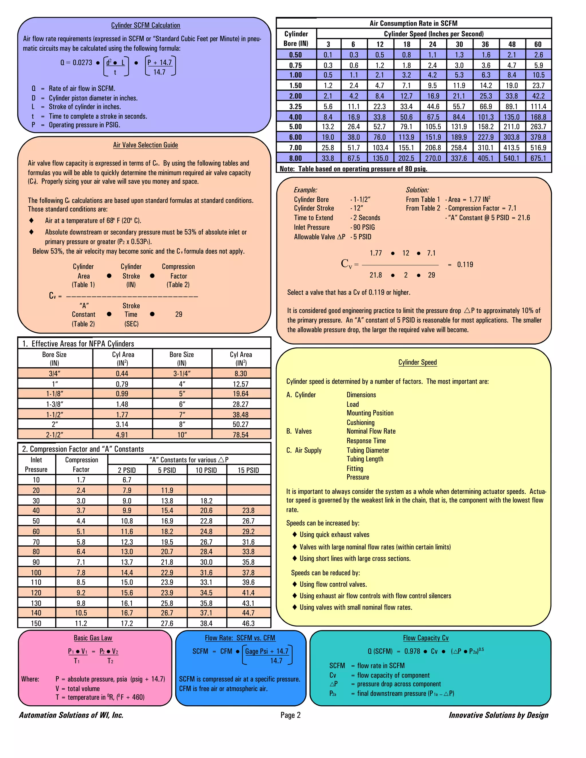
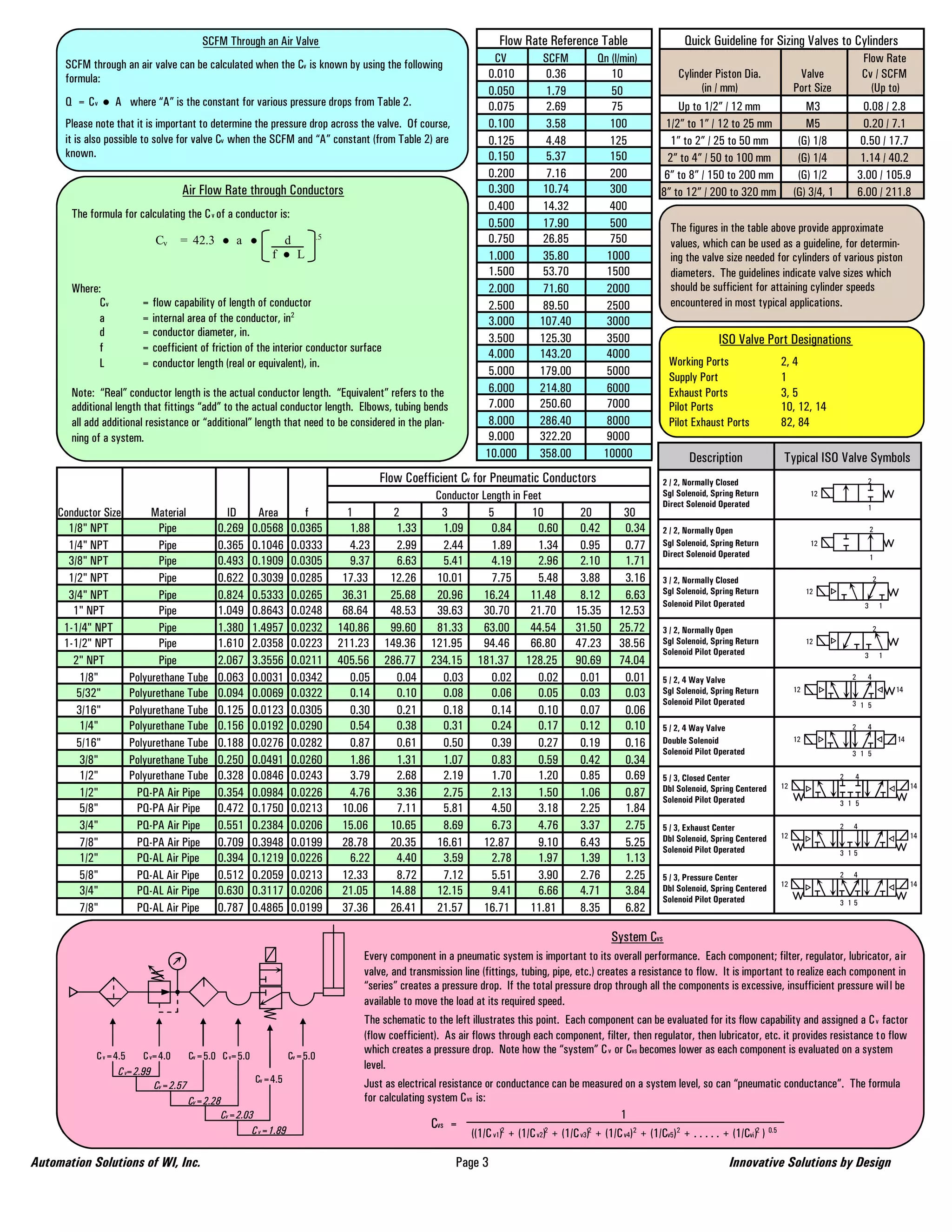
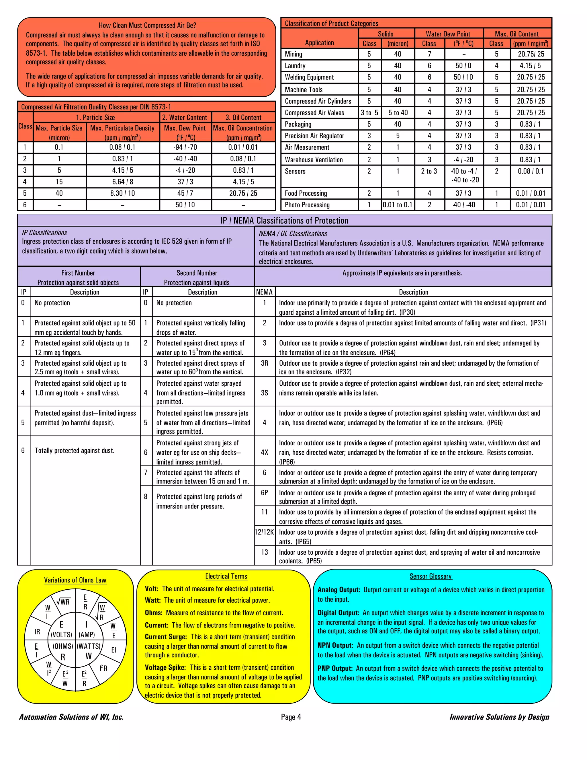
This document provides technical information for selecting and sizing cylinders, vacuum cups, valves, and other pneumatic components. It includes tables for determining cylinder force output based on piston size and pressure, formulas for calculating air flow requirements, and guidelines for selecting vacuum cup size and air valves based on flow needs. Conversion tables are also included for common units like pressure, volume, temperature and more.
Welcome to International Journal of Engineering Research and Development (IJERD)IJERD Editor
call for paper 2012, hard copy of journal, research paper publishing, where to publish research paper,
journal publishing, how to publish research paper, Call For research paper, international journal, publishing a paper, IJERD, journal of science and technology, how to get a research paper published, publishing a paper, publishing of journal, publishing of research paper, reserach and review articles, IJERD Journal, How to publish your research paper, publish research paper, open access engineering journal, Engineering journal, Mathemetics journal, Physics journal, Chemistry journal, Computer Engineering, Computer Science journal, how to submit your paper, peer reviw journal, indexed journal, reserach and review articles, engineering journal, www.ijerd.com, research journals,
yahoo journals, bing journals, International Journal of Engineering Research and Development, google journals, hard copy of journal
Volvo EC55B Compact Excavator Service Repair Manualfujdfjjskrtekme
This is the Highly Detailed factory service repair manual for theVOLVO EC55B COMPACT EXCAVATOR, this Service Manual has detailed illustrations as well as step by step instructions,It is 100 percents complete and intact. they are specifically written for the do-it-yourself-er as well as the experienced mechanic.VOLVO EC55B COMPACT EXCAVATOR Service Repair Workshop Manual provides step-by-step instructions based on the complete dis-assembly of the machine. It is this level of detail, along with hundreds of photos and illustrations, that guide the reader through each service and repair procedure. Complete download comes in pdf format which can work under all PC based windows operating system and Mac also, All pages are printable. Using this repair manual is an inexpensive way to keep your vehicle working properly.
Service Repair Manual Covers:
Safety
General
Standard Parts, Service
Engine with Mounting and Equipment
Elec. System, Warning System, Information System, Instruments
Power Transmission
Frame and Crawler Unit
Machinery House, Cab, Exterior Trim Parts Anywhere
Hydraulic System, Digging, Handling, Grading Equipment, Misc Equipment
Hydraulic and Electrical Schematics
File Format: PDF
Compatible: All Versions of Windows & Mac
Language: English
Requirements: Adobe PDF Reader
NO waiting, Buy from responsible seller and get INSTANT DOWNLOAD, Without wasting your hard-owned money on uncertainty or surprise! All pages are is great to haveVOLVO EC55B COMPACT EXCAVATOR Service Repair Workshop Manual.
Looking for some other Service Repair Manual,please check:
https://www.aservicemanualpdf.com/
Thanks for visiting!
Volvo EC55B Compact Excavator Service Repair Manual.pdf
ASI Technical Reference Guide
1. 1115 Liebau Road
Of P.O. Box 610
WI Mequon, WI 53092
Inc Phone: (262)243-0103
Innovative Solutions by Design Fax: (262)243-0108
Technical Reference Guide
Cylinder Force Cylinder Output Force (lbf)
Cylinders are selected on the basis of the required force and travel distance. Piston Operating Pressure (PSI)
The formula for cylinder sizing is: Dia. (in)
F = (Pressure x Area) - Friction 20 30 40 50 60 70 80 90 100 120 150
1/2 3.5 5.3 7.1 8.8 10.6 12.4 14.1 15.9 17.7 21.2 26.5
Use the parameters shown below for directly calculating piston force. 3/4 8 11.9 15.9 19.9 23.9 27.8 31.8 35.8 39.8 47.7 59.6
F = (P x d 2 x 0.7854) - Friction 1 14.1 21.2 28.3 35.3 42.4 49.5 56.5 63.6 70.7 84.8 106
F = Piston Force (lbs) 1-1/2 31.8 47.7 63.6 79.5 95.4 111.3 127.2 143.1 159 190.9 238.6
P = Operating Pressure (PSI) 2 56.5 84.8 113.1 141.4 169.6 197.9 226.2 254.5 282.7 339.3 424.1
d = Piston Diameter (inches) 3-1/4 149 224 298.6 373.3 448 522.6 597.3 672 746.6 895.9 1120
Friction = internal efficiency of cylinder (lbs) 4 226 339.3 452.4 565.5 678.6 791.7 904.8 1018 1131 1357 1697
The reference table is based on a friction factor of 10% of total force. 5 353 530.1 706.9 883.6 1060 1237 1414 1590 1767 2121 2651
6 509 763.4 1018 1272 1527 1781 2036 2290 2545 3054 3817
Column Strength and Stop Tube 7 693 1039 1385 1732 2078 2425 2771 3117 3464 4156 5195
Long stroke cylinders must be evaluated for column strength. That is, the 8 905 1357 1810 2262 2714 3167 3619 4072 4524 5429 6786
potential for rod buckling at the required output force. Column strength is International Vacuum / Pressure Conversion Table
evaluated on the basis of output force, rod diameter, cylinder mounting style,
and rod support. Consult the manufacturers recommendations for proper sizing. atm, torr,
Stop tube may also be required. Again, consult manufacturers recommenda- Unit bar N/cm 2 kPa kp/cm2 in H 2O mm Hg in Hg psi
tions. bar 1 10 100 1.0197 1.0197 750.06 29.54 14.5
N/cm2 0.1 1 10 0.1019 0.1019 75.006 2.954 1.45
Common Conversion Factors Vacuum Conversion Table kPa 0.01 0.1 1 0.0102 0.0102 7.5006 0.2954 0.145
Linear Measure Rela- Pressure, atm, kp/cm 2 0.9807 9.807 98.07 1 1 735.56 28.97 14.22
Inches x 25.4 = millmeters tive Relative in H 2O 0.9807 9.807 98.07 1 1 735.56 28.97 14.22
feet x 0.3048 = meters Vacuum (bar) In Hg torr, mm Hg 0.00133 0.01333 0.1333 0.00136 0.00136 1 0.0394 0.0193
Weights 10% -0.101 -3 in Hg 0.0338 0.3385 3.885 0.03446 0.03446 25.35 1 0.49
ounces x 28.35 = grams
20% -0.203 -6 psi 0.0689 0.6896 6.896 0.0703 0.0703 51.68 2.035 1
grams x 0.03527 = ounces
pounds x 0.4536 = kilograms 30% -0.304 -9
Suction Cup Sizing Method
kilograms x 2.2046 = pounds 40% -0.405 -12
50% -0.507 -15 1. Determine holding force FH = Theoretical holding force of the suction
Force
Pounds force x 4.4482 = Newtons gripper (N)
60% -0.608 -18 Case 1: Horizontal suction gripper position, vertical
Newtons x 0.2248 = Pounds force m = Mass (kg)
70% -0.709 -21 direction of movement (most favorable move- g = Acceleration due to gravity (9.81 m/s2)
Torque 80% -0.811 -24 ment).
Pound inches x 0.113 = Newton meters a = Acceleration of the system (m/s2 )
90% -0.912 -27 S = Safety Factor
Newton meters x 8.851 = Pound inches
Flow Vacuum Solutions F H = m x (g + a) x S (minimum value is a safety factor of 1.5,
for critical, non uniform or porous materi-
Liters/minute x 0.0353 = SCFM
als or rough surfaces this should be 2.0
SCFM x 28.3 = Liters/minute Case 2: Horizontal suction gripper position, horizontal or higher)
Temperature direction of movement.
(oCelsius x 1.8) +32 = oFahrenheit = Friction factor
(oFahrenheit—32) x (5/9) = oCelsius 0.1 for oily surfaces
F H = m x (g + a/x S
) 0.2 . . . 0.3 for wet surfaces
Fieldbus Solutions—The Latest Technology 0.5 for wood, metal, glass, stone, etc.
Case 3: Vertical suction gripper position, vertical 0.6 for rough surfaces
direction of movement (least favorable case). FA = Theoretical breakaway force (N)
n = Number of suction cups
D = Diameter of suction cup
F H = (m/ x (g + a) x S U = Vacuum (bar)
Design Tip:
Recommended Design Pressure = -0.6 bar.
2. Determine breakaway force The energy required creating –0.6 bar is low in
comparison to that required to generate –0.9 bar. If
F A = FH a vacuum system is designed for –0.9 bar there is
n very little capacity left in the pump performance,
thus no margin for error. Vacuum pads running at
3. Calculate Cup Diameter –0.9 bar adhere to the surface with far more con-
FA = 0.07854 x U x d 2 or d = 3.568 x (FA/U) 0.5 tact force, thereby stressing the pad more, which
Call your local Automation Solutions sales professional for a demonstration! results in premature wear of the pad.
Motion Control Electric Actuators Modular Automation
Modular Robotics System Design Integrated Manifold Systems
Pneumatics Vacuum Hydraulics
2. Cylinder SCFM Calculation Air Consumption Rate in SCFM
Cylinder Cylinder Speed (Inches per Second)
Air flow rate requirements (expressed in SCFM or “Standard Cubic Feet per Minute) in pneu-
Bore (IN) 3 6 12 18 24 30 36 48 60
matic circuits may be calculated using the following formula:
0.50 0.1 0.3 0.5 0.8 1.1 1.3 1.6 2.1 2.6
Q = 0.0273 d2 L P + 14.7 0.75 0.3 0.6 1.2 1.8 2.4 3.0 3.6 4.7 5.9
t 14.7 1.00 0.5 1.1 2.1 3.2 4.2 5.3 6.3 8.4 10.5
Q = Rate of air flow in SCFM. 1.50 1.2 2.4 4.7 7.1 9.5 11.9 14.2 19.0 23.7
D = Cylinder piston diameter in inches. 2.00 2.1 4.2 8.4 12.7 16.9 21.1 25.3 33.8 42.2
L = Stroke of cylinder in inches. 3.25 5.6 11.1 22.3 33.4 44.6 55.7 66.9 89.1 111.4
t = Time to complete a stroke in seconds. 4.00 8.4 16.9 33.8 50.6 67.5 84.4 101.3 135.0 168.8
P = Operating pressure in PSIG. 5.00 13.2 26.4 52.7 79.1 105.5 131.9 158.2 211.0 263.7
6.00 19.0 38.0 76.0 113.9 151.9 189.9 227.9 303.8 379.8
Air Valve Selection Guide 7.00 25.8 51.7 103.4 155.1 206.8 258.4 310.1 413.5 516.9
8.00 33.8 67.5 135.0 202.5 270.0 337.6 405.1 540.1 675.1
Air valve flow capacity is expressed in terms of Cv. By using the following tables and
formulas you will be able to quickly determine the minimum required air valve capacity Note: Table based on operating pressure of 80 psig.
(Cv). Properly sizing your air valve will save you money and space.
Example: Solution:
The following Cv calculations are based upon standard formulas at standard conditions. Cylinder Bore - 1-1/2” From Table 1 - Area = 1.77 IN2
Those standard conditions are: Cylinder Stroke - 12” From Table 2 - Compression Factor = 7.1
Air at a temperature of 68o F (20o C).
Time to Extend - 2 Seconds - “A” Constant @ 5 PSID = 21.6
Inlet Pressure - 90 PSIG
Absolute downstream or secondary pressure must be 53% of absolute inlet or
Allowable Valve P - 5 PSID
primary pressure or greater (P2 x 0.53P1).
Below 53%, the air velocity may become sonic and the C v formula does not apply. 1.77 12 7.1
Cylinder Cylinder Compression Cv = —————————— = 0.119
Area Stroke Factor 21.8 2 29
(Table 1) (IN) (Table 2)
Cv = —————————————————————————— Select a valve that has a Cv of 0.119 or higher.
“A” Stroke
Constant Time 29 It is considered good engineering practice to limit the pressure drop P to approximately 10% of
(Table 2) (SEC) the primary pressure. An “A” constant of 5 PSID is reasonable for most applications. The smaller
the allowable pressure drop, the larger the required valve will become.
1. Effective Areas for NFPA Cylinders
Bore Size Cyl Area Bore Size Cyl Area
(IN) (IN2) (IN) (IN2) Cylinder Speed
3/4” 0.44 3-1/4” 8.30
1” 0.79 4” 12.57 Cylinder speed is determined by a number of factors. The most important are:
1-1/8” 0.99 5” 19.64 A. Cylinder Dimensions
1-3/8” 1.48 6” 28.27 Load
1-1/2” 1.77 7” 38.48 Mounting Position
2” 3.14 8” 50.27 Cushioning
2-1/2” 4.91 10” 78.54 B. Valves Nominal Flow Rate
Response Time
2. Compression Factor and “A” Constants C. Air Supply Tubing Diameter
Inlet Compression “A” Constants for various P Tubing Length
Pressure Factor 2 PSID 5 PSID 10 PSID 15 PSID Fitting
10 1.7 6.7 Pressure
20 2.4 7.9 11.9 It is important to always consider the system as a whole when determining actuator speeds. Actua-
30 3.0 9.0 13.8 18.2 tor speed is governed by the weakest link in the chain, that is, the component with the lowest flow
40 3.7 9.9 15.4 20.6 23.8 rate.
50 4.4 10.8 16.9 22.8 26.7 Speeds can be increased by:
60 5.1 11.6 18.2 24.8 29.2 quick exhaust valves
Using
70 5.8 12.3 19.5 26.7 31.6
with large nominal flow rates (within certain limits)
Valves
80 6.4 13.0 20.7 28.4 33.8
90 7.1 13.7 21.8 30.0 35.8 short lines with large cross sections.
Using
100 7.8 14.4 22.9 31.6 37.8 Speeds can be reduced by:
110 8.5 15.0 23.9 33.1 39.6 flow control valves.
Using
120 9.2 15.6 23.9 34.5 41.4 exhaust air flow controls with flow control silencers
Using
130 9.8 16.1 25.8 35.8 43.1 valves with small nominal flow rates.
Using
140 10.5 16.7 26.7 37.1 44.7
150 11.2 17.2 27.6 38.4 46.3
Basic Gas Law Flow Rate: SCFM vs. CFM Flow Capacity Cv
P 1 V 1 = P2 V 2 SCFM = CFM Gage Psi + 14.7
Q (SCFM) = 0.978 Cv (P P 2a)0.5
T1 T2 14.7
SCFM = flow rate in SCFM
Where: P = absolute pressure, psia (psig + 14.7) SCFM is compressed air at a specific pressure. Cv = flow capacity of component
P = pressure drop across component
V = total volume CFM is free air or atmospheric air.
T = temperature in 0R, (0 F + 460) P2a = final downstream pressure (P 1a — P)
Automation Solutions of WI, Inc. Page 2 Innovative Solutions by Design
3. SCFM Through an Air Valve Flow Rate Reference Table Quick Guideline for Sizing Valves to Cylinders
SCFM through an air valve can be calculated when the Cv is known by using the following CV SCFM Qn (l/min) Flow Rate
formula: 0.010 0.36 10 Cylinder Piston Dia. Valve Cv / SCFM
0.050 1.79 50 (in / mm) Port Size (Up to)
Q = Cv A where “A” is the constant for various pressure drops from Table 2. 0.075 2.69 75 Up to 1/2” / 12 mm M3 0.08 / 2.8
Please note that it is important to determine the pressure drop across the valve. Of course, 0.100 3.58 100 1/2” to 1” / 12 to 25 mm M5 0.20 / 7.1
it is also possible to solve for valve Cv when the SCFM and “A” constant (from Table 2) are 0.125 4.48 125 1” to 2” / 25 to 50 mm (G) 1/8 0.50 / 17.7
known. 0.150 5.37 150 2” to 4” / 50 to 100 mm (G) 1/4 1.14 / 40.2
0.200 7.16 200 6” to 8” / 150 to 200 mm (G) 1/2 3.00 / 105.9
Air Flow Rate through Conductors 0.300 10.74 300 8” to 12” / 200 to 320 mm (G) 3/4, 1 6.00 / 211.8
0.400 14.32 400
The formula for calculating the C v of a conductor is:
0.500 17.90 500 The figures in the table above provide approximate
Cv = 42.3 a d .5 0.750 26.85 750 values, which can be used as a guideline, for determin-
f L 1.000 35.80 1000 ing the valve size needed for cylinders of various piston
1.500 53.70 1500 diameters. The guidelines indicate valve sizes which
Where: 2.000 71.60 2000 should be sufficient for attaining cylinder speeds
Cv = flow capability of length of conductor 2.500 89.50 2500 encountered in most typical applications.
a = internal area of the conductor, in2 3.000 107.40 3000
d = conductor diameter, in. 3.500 125.30 3500 ISO Valve Port Designations
f = coefficient of friction of the interior conductor surface 4.000 143.20 4000
L = conductor length (real or equivalent), in. Working Ports 2, 4
5.000 179.00 5000 Supply Port 1
Note: “Real” conductor length is the actual conductor length. “Equivalent” refers to the 6.000 214.80 6000 Exhaust Ports 3, 5
additional length that fittings “add” to the actual conductor length. Elbows, tubing bends 7.000 250.60 7000 Pilot Ports 10, 12, 14
all add additional resistance or “additional” length that need to be considered in the plan- 8.000 286.40 8000 Pilot Exhaust Ports 82, 84
ning of a system. 9.000 322.20 9000
10.000 358.00 10000 Description Typical ISO Valve Symbols
Flow Coefficient Cv for Pneumatic Conductors 2 / 2, Normally Closed 2
Conductor Length in Feet Sgl Solenoid, Spring Return 12
Direct Solenoid Operated 1
Conductor Size Material ID Area f 1 2 3 5 10 20 30
1/8" NPT Pipe 0.269 0.0568 0.0365 1.88 1.33 1.09 0.84 0.60 0.42 0.34 2 / 2, Normally Open 2
1/4" NPT Pipe 0.365 0.1046 0.0333 4.23 2.99 2.44 1.89 1.34 0.95 0.77 Sgl Solenoid, Spring Return 12
Direct Solenoid Operated 1
3/8" NPT Pipe 0.493 0.1909 0.0305 9.37 6.63 5.41 4.19 2.96 2.10 1.71
1/2" NPT Pipe 0.622 0.3039 0.0285 17.33 12.26 10.01 7.75 5.48 3.88 3.16 3 / 2, Normally Closed 2
Sgl Solenoid, Spring Return 12
3/4" NPT Pipe 0.824 0.5333 0.0265 36.31 25.68 20.96 16.24 11.48 8.12 6.63
Solenoid Pilot Operated 3 1
1" NPT Pipe 1.049 0.8643 0.0248 68.64 48.53 39.63 30.70 21.70 15.35 12.53
1-1/4" NPT Pipe 1.380 1.4957 0.0232 140.86 99.60 81.33 63.00 44.54 31.50 25.72 3 / 2, Normally Open 2
1-1/2" NPT Pipe 1.610 2.0358 0.0223 211.23 149.36 121.95 94.46 66.80 47.23 38.56 Sgl Solenoid, Spring Return 12
Solenoid Pilot Operated 3 1
2" NPT Pipe 2.067 3.3556 0.0211 405.56 286.77 234.15 181.37 128.25 90.69 74.04
1/8" Polyurethane Tube 0.063 0.0031 0.0342 0.05 0.04 0.03 0.02 0.02 0.01 0.01 5 / 2, 4 Way Valve 2 4
Sgl Solenoid, Spring Return 12 14
5/32" Polyurethane Tube 0.094 0.0069 0.0322 0.14 0.10 0.08 0.06 0.05 0.03 0.03
Solenoid Pilot Operated 3 1 5
3/16" Polyurethane Tube 0.125 0.0123 0.0305 0.30 0.21 0.18 0.14 0.10 0.07 0.06
1/4" Polyurethane Tube 0.156 0.0192 0.0290 0.54 0.38 0.31 0.24 0.17 0.12 0.10 5 / 2, 4 Way Valve 2 4
Double Solenoid 12 14
5/16" Polyurethane Tube 0.188 0.0276 0.0282 0.87 0.61 0.50 0.39 0.27 0.19 0.16
Solenoid Pilot Operated 3 1 5
3/8" Polyurethane Tube 0.250 0.0491 0.0260 1.86 1.31 1.07 0.83 0.59 0.42 0.34
1/2" Polyurethane Tube 0.328 0.0846 0.0243 3.79 2.68 2.19 1.70 1.20 0.85 0.69 5 / 3, Closed Center 2 4
Dbl Solenoid, Spring Centered 12 14
1/2" PQ-PA Air Pipe 0.354 0.0984 0.0226 4.76 3.36 2.75 2.13 1.50 1.06 0.87 Solenoid Pilot Operated 3 1 5
5/8" PQ-PA Air Pipe 0.472 0.1750 0.0213 10.06 7.11 5.81 4.50 3.18 2.25 1.84
3/4" PQ-PA Air Pipe 0.551 0.2384 0.0206 15.06 10.65 8.69 6.73 4.76 3.37 2.75 5 / 3, Exhaust Center 2 4
Dbl Solenoid, Spring Centered 12 14
7/8" PQ-PA Air Pipe 0.709 0.3948 0.0199 28.78 20.35 16.61 12.87 9.10 6.43 5.25 Solenoid Pilot Operated 3 15
1/2" PQ-AL Air Pipe 0.394 0.1219 0.0226 6.22 4.40 3.59 2.78 1.97 1.39 1.13
5/8" PQ-AL Air Pipe 0.512 0.2059 0.0213 12.33 8.72 7.12 5.51 3.90 2.76 2.25 5 / 3, Pressure Center 2 4
12 14
3/4" PQ-AL Air Pipe 0.630 0.3117 0.0206 21.05 14.88 12.15 9.41 6.66 4.71 3.84 Dbl Solenoid, Spring Centered
Solenoid Pilot Operated 3 15
7/8" PQ-AL Air Pipe 0.787 0.4865 0.0199 37.36 26.41 21.57 16.71 11.81 8.35 6.82
System Cvs
Every component in a pneumatic system is important to its overall performance. Each component; filter, regulator, lubricator, air
valve, and transmission line (fittings, tubing, pipe, etc.) creates a resistance to flow. It is important to realize each component in
“series” creates a pressure drop. If the total pressure drop through all the components is excessive, insufficient pressure wil l be
available to move the load at its required speed.
The schematic to the left illustrates this point. Each component can be evaluated for its flow capability and assigned a C v factor
(flow coefficient). As air flows through each component, filter, then regulator, then lubricator, etc. it provides resistance to flow
C v =4.5 C v=4.0 Cv =5.0 C v=5.0 Cv =5.0
which creates a pressure drop. Note how the “system” C v or Cvs becomes lower as each component is evaluated on a system
C v=2.99
level.
Cv =4.5 Just as electrical resistance or conductance can be measured on a system level, so can “pneumatic conductance”. The formula
Cv =2.57
Cv =2.28 for calculating system Cvs is:
Cv =2.03 1
C v =1.89
Cvs =
((1/C v1)2 + (1/C v2)2 + (1/C v3)2 + (1/C v4)2 + (1/Cv5)2 + . . . . . + (1/Cvi )2 ) 0.5
Automation Solutions of WI, Inc. Page 3 Innovative Solutions by Design
4. How Clean Must Compressed Air Be? Classification of Product Categories
Compressed air must always be clean enough so that it causes no malfunction or damage to Solids Water Dew Point Max. Oil Content
components. The quality of compressed air is identified by quality classes set forth in ISO Application Class (micron) Class (0F / 0C) Class (ppm / mg/m3)
8573-1. The table below establishes which contaminants are allowable in the corresponding Mining 5 40 7 -- 5 20.75/ 25
compressed air quality classes. Laundry 5 40 6 50 / 0 4 4.15 / 5
The wide range of applications for compressed air imposes variable demands for air quality. Welding Equipment 5 40 6 50 / 10 5 20.75 / 25
If a high quality of compressed air is required, more steps of filtration must be used.
Machine Tools 5 40 4 37 / 3 5 20.75 / 25
Compressed Air Cylinders 5 40 4 37 / 3 5 20.75 / 25
Compressed Air Filtration Quality Classes per DIN 8573-1
Compressed Air Valves 3 to 5 5 to 40 4 37 / 3 5 20.75 / 25
1. Particle Size 2. Water Content 3. Oil Content
Class Max. Particle Size Max. Particulate Density Max. Dew Point Max. Oil Concentration Packaging 5 40 4 37 / 3 3 0.83 / 1
(micron) (ppm / mg/m3 ) (û F / ûC) (ppm / mg/m3) Precision Air Regulator 3 5 4 37 / 3 3 0.83 / 1
1 0.1 0.08 / 0.1 -94 / -70 0.01 / 0.01 Air Measurement 2 1 4 37 / 3 3 0.83 / 1
2 1 0.83 / 1 -40 / -40 0.08 / 0.1 Warehouse Ventilation 2 1 3 -4 / -20 3 0.83 / 1
3 5 4.15 / 5 -4 / -20 0.83 / 1 Sensors 2 1 2 to 3 -40 to -4 / 2 0.08 / 0.1
4 15 6.64 / 8 37 / 3 4.15 / 5 -40 to -20
5 40 8.30 / 10 45 / 7 20.75 / 25 Food Processing 2 1 4 37 / 3 1 0.01 / 0.01
6 – – 50 / 10 – Photo Processing 1 0.01 to 0.1 2 -40 / -40 1 0.01 / 0.01
IP / NEMA Classifications of Protection
IP Classifications NEMA / UL Classifications
Ingress protection class of enclosures is according to IEC 529 given in form of IP The National Electrical Manufacturers Association is a U.S. Manufacturers organization. NEMA performance
classification, a two digit coding which is shown below. criteria and test methods are used by Underwriters’ Laboratories as guidelines for investigation and listing of
electrical enclosures.
First Number Second Number Approximate IP equivalents are in parenthesis.
Protection against solid objects Protection against liquids
IP Description IP Description NEMA Description
0 No protection 0 No protection 1 Indoor use primarily to provide a degree of protection against contact with the enclosed equipment and
guard against a limited amount of falling dirt. (IP30)
1 Protected against solid object up to 50 1 Protected against vertically falling 2 Indoor use to provide a degree of protection against limited amounts of falling water and direct. (IP31)
mm eg accidental touch by hands. drops of water.
2 Protected against solid objects up to 2 Protected against direct sprays of 3 Outdoor use to provide a degree of protection against windblown dust, rain and sleet; undamaged by
12 mm eg fingers. water up to 150 from the vertical. the formation of ice on the enclosure. (IP64)
3 Protected against solid object up to 3 Protected against direct sprays of 3R Outdoor use to provide a degree of protection against rain and sleet; undamaged by the formation of
2.5 mm eg (tools + small wires). water up to 600 from the vertical. ice on the enclosure. (IP32)
Protected against solid object up to Protected against water sprayed Outdoor use to provide a degree of protection against windblown dust, rain and sleet; external mecha-
4 1.0 mm eg (tools + small wires). 4 from all directions—limited ingress 3S nisms remain operable while ice laden.
permitted.
Protected against dust—limited ingress Protected against low pressure jets Indoor or outdoor use to provide a degree of protection against splashing water, windblown dust and
5 permitted (no harmful deposit). 5 of water from all directions—limited 4 rain, hose directed water; undamaged by the formation of ice on the enclosure. (IP66)
ingress permitted.
Protected against strong jets of Indoor or outdoor use to provide a degree of protection against splashing water, windblown dust and
6 Totally protected against dust. 6 water eg for use on ship decks— 4X rain, hose directed water; undamaged by the formation of ice on the enclosure. Resists corrosion.
limited ingress permitted. (IP66)
7 Protected against the affects of 6 Indoor or outdoor use to provide a degree of protection against the entry of water during temporary
immersion between 15 cm and 1 m. submersion at a limited depth; undamaged by the formation of ice on the enclosure.
8 Protected against long periods of 6P Indoor or outdoor use to provide a degree of protection against the entry of water during prolonged
submersion at a limited depth.
immersion under pressure.
11 Indoor use to provide by oil immersion a degree of protection of the enclosed equipment against the
corrosive effects of corrosive liquids and gases.
12/12K Indoor use to provide a degree of protection against dust, falling dirt and dripping noncorrosive cool-
ants. (IP65)
13 Indoor use to provide a degree of protection against dust, and spraying of water oil and noncorrosive
coolants. (IP65)
Variations of Ohms Law Electrical Terms Sensor Glossary
Volt: The unit of measure for electrical potential. Analog Output: Output current or voltage of a device which varies in direct proportion
E Watt: The unit of measure for electrical power. to the input.
WR
W R W
I Ohms: Measure of resistance to the flow of current. Digital Output: An output which changes value by a discrete increment in response to
R
E I W Current: The flow of electrons from negative to positive. an incremental change in the input signal. If a device has only two unique values for
IR (VOLTS) (AMP) the output, such as ON and OFF, the digital output may also be called a binary output.
E Current Surge: This is a short term (transient) condition
E (OHMS) (WATTS) causing a larger than normal amount of current to flow NPN Output: An output from a switch device which connects the negative potential
EI
I R W through a conductor. to the load when the device is actuated. NPN outputs are negative switching (sinking).
W I2 R Voltage Spike: This is a short term (transient) condition PNP Output: An output from a switch device which connects the positive potential to
I2 E2 E2 causing a larger than normal amount of voltage to be applied the load when the device is actuated. PNP outputs are positive switching (sourcing).
W R to a circuit. Voltage spikes can often cause damage to an
electric device that is not properly protected.
Automation Solutions of WI, Inc. Page 4 Innovative Solutions by Design