Download as PDF, PPTX

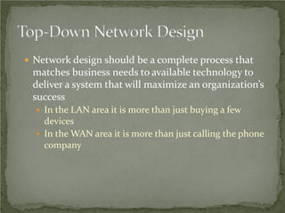


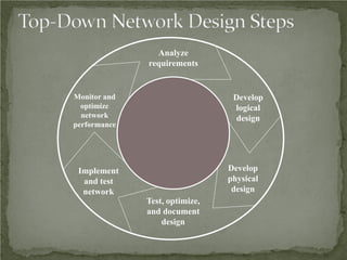
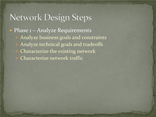
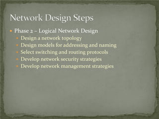

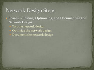
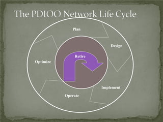


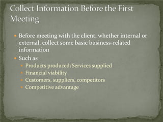


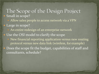
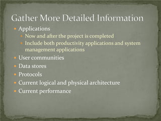

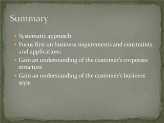
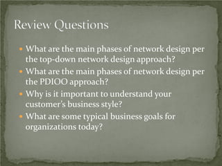

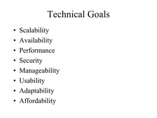


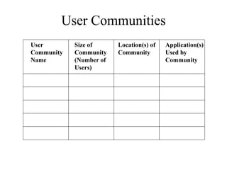
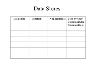
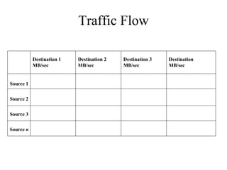
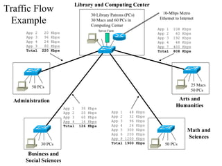


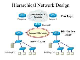
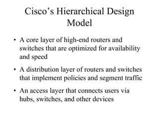


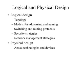
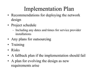

The document discusses that network design should be a complete process that analyzes business needs and goals, explores technical options, and delivers a system to maximize success; it emphasizes analyzing applications, users, and technical goals like performance, scalability, availability, and security before designing network structures and selecting specific technologies. The document also outlines phases of network design like requirements analysis, logical and physical design, testing, and optimization according to the systems development life cycle approach.


![Chapternetworkdesign d1 [Autosaved].pptx](https://cdn.slidesharecdn.com/ss_thumbnails/chapternetworkdesign1autosaved-240426182609-f2d9ab3f-thumbnail.jpg?width=640&height=640&fit=bounds)


