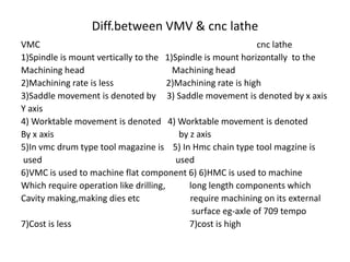
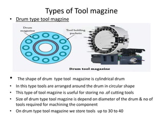
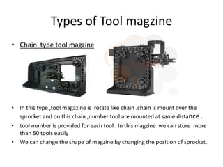
Hot And Sexy 🥵 Call Girls Delhi Daryaganj {9711199171} Ira Malik High class G...
AMP\AMP 2nd chapter.pptx
1. Unit no.2 fundamentals of computer aided
manufacturing
Advantages of CNC machine
• We can manufacture the component with high accuracy
• Less floor space is required
• Required less time for manufacturing the component
• Inspection time is less
• Inspection cost is less
• High rate of machining
• Lead time of manufacturing the component is less
• set up time required for the component is less
• Obtain good surface finish of the component
• Rejection of component is minimised
• Increase market value of the company
2. open loop control system
• As there is no feedback device present this system is called as open loop
control system
• CNC programme is given to cnc machine by using proper input device
(keyboard & CPU)
• Cnc programme having programmable language i.e G code & M code
3. open loop control system
• Machine control unit can convert this programmable language in to
electrical signals
• Stepper motor takes takes electrical signals & produce angular movement
• As stepper motor rotates lead screw also rotates
• Angular movement of lead screw is convert in to linear movement of
worktable by suitable mechanism
• As we can not measure actual displacement of worktable ,we can not say
that component is manufactured accurately because external conditions
i.e.wear of lead screw ,machine vibrations,affect on movement of work
table
• Therefor open loop control system can not used for manufacturing precise
components
4. closed loop control system
• As there is feedback device present this system is called as closed loop
control system
• CNC programme is given to cnc machine by using proper input device
(keyboard & CPU)
• Cnc programme having programmable language i.e G code & M code
5. closed loop control system
• Machine control unit can convert this programmable language in to
electrical signals
• Stepper motor takes takes electrical signals & produce angular movement
• As stepper motor rotates lead screw also rotates
• Angular movement of lead screw is convert in to linear movement of
worktable by suitable mechanism
• As there is feedback device present we can measure actual displacement
of worktable
• Tranducer is act as feedback device .it can give feedback signal to
comparator
• Comparator compares feedback signal with input signal & generate error
signal & gives to MCU
6. closed loop control system
• MCU add this error signal in to the input signal & give corrected signal to
the stepper motor
• Eg.suppose input signal is X=10 mm is given in the CNC programme .In
actual condition movement of worktable is 9.5mm due to wear of lead
screw .then feedback device gives feedback signal 9.5mm to the
comparator .comparator can compare 9.5mm feedback signal with input
signal 10mm & produce error signal 0.5mm .MCU can give corrected
signal i.e.10+0.5=10.5mm to the stepper motor hence work table can mov
e 10mm & we can achieve correct movement of worktable
• closed loop control system is used for manufacturing the components with
high accuracy
8. Axis identification of VMC
• X axis-
• In vmc x axis is the horizontal movement of worktable parallel
to the work piece surface
• Reference point is always at left corner of the workpiece
• It is the longitudinal movement of work piece
• By considering Cartesian co-ordinate system x is positive away
from the work piece in the right side from reference point & x
is negative in the left direction from reference point
• Normally dimensions of x axis are always positive because
reference point is set at left corner of the workpiece
9. Axis identification of VMC
Z axis
• Z axis is always perpendicular to x & y axis
• Vertical up & down movement of spindle is denoted by Z axis
• Reference point is on top surface of work piece
• Z axis is positive when we go away from the work piece in
vertical direction from reference point of work piece
• Z axis is negative when spindle go downwards to the work
piece in vertical direction from reference point of work piece
• in case of drilling operation z is always negative because tool
is move downward direction from reference point of work
piece
10. Axis identification of VMC
• Y axis
• Y axis is nothing but cross movement of saddle
• Y axis is positive when spindle(tool) goes towards x+ & Z+
direction
• Y axis is negative when spindle (tool) goes towards x- & Z-
direction
Rotary axis - (A,B,C axis)
1) It is the Axis of rotation of cutting tool towards x ,y & Z axis
2) A axis-When cutting tool revolve in clockwise direction &
moves towards x axis,it is denoted by A+
11. Axis identification of VMC
• B axis-When cutting tool revolve in clockwise direction &
moves towards y axis,it is denoted by B axis
• C axis-When cutting tool revolve in clockwise direction
towards & moves towards z axis,it is denoted by C axis
12. Axis identification of CNC lathe machine
X axis-
• when tool moves in transverse direction from the reference
position then it is considered as x axis
• Workpiece center is considered as reference position
• When tool moves towards the workpiece from reference position
then x is –Ve & When tool moves away from the workpiece from
reference position then x is +Ve
13. Axis identification of CNC lathe machine
Z axis-
• Z axis is nothing but it is the Longitudenal movement of tool
along workpiece
• Reference position is set at the outer diameter of workpiece &
at the extreme right side of the workpiece
• Z is positive when tool moves right side from the Reference
position of workpiece
• Z is negative when tool moves left side from the Reference
position of workpiece
14. Diff.between VMV & cnc lathe
VMC cnc lathe
1)Spindle is mount vertically to the 1)Spindle is mount horizontally to the
Machining head Machining head
2)Machining rate is less 2)Machining rate is high
3)Saddle movement is denoted by 3) Saddle movement is denoted by x axis
Y axis
4) Worktable movement is denoted 4) Worktable movement is denoted
By x axis by z axis
5)In vmc drum type tool magazine is 5) In Hmc chain type tool magzine is
used used
6)VMC is used to machine flat component 6) 6)HMC is used to machine
Which require operation like drilling, long length components which
Cavity making,making dies etc require machining on its external
surface eg-axle of 709 tempo
7)Cost is less 7)cost is high
15. ATC(Automatic tool changing mechanism)
Importance of ATC
• For performing machining of component no of tools are
required
• For maximum utilization of cnc machine ,idle time of cutting
tool should be minimum
• ATC plays useful role for minimizing tool change time
• It having tool changing arm .when M06 command is executed
then tool changing arm come near the spindle & it takes out
current tool from the spindle then arm goes to the tool
magzine .kept that tool in the tool magzine & take required
tool from tool magzine & load that tool in the spindle
• when operation is completed with that tool then again
16. ATC(Automatic tool changing mechanism)
• takes out current tool from the spindle then arm goes to the
tool magzine .kept that tool in the tool magzine & take
required tool as written in the cnc programme from tool
magzine & load that tool in the spindle
• Operator is not required for tool change
• Tool changing time is about 5 to 10 sec
17. Tool magzine
• The tool magazine system is a device for the storage and tool
change required in the automated machining process of CNC
machining center. Its automatic tool change mechanism and
tool magazine that can store multiple tools have changed the
traditional production method based on people. Through the
control of the computer program, various processing
requirements can be completed, such as milling, drilling,
boring, tapping, etc., which greatly shortens the processing
time and reduces the production cost, which is the biggest
feature of the tool magazine system.
18. Types of Tool magzine
• Drum type tool magzine
• The shape of drum type tool magazine is cylindrical drum
• In this type tools are arranged around the drum in circular shape
• This type of tool magzine is useful for storing no .of cutting tools
• Size of drum type tool magzine is depend on diameter of the drum & no of
tools required for machining the component
• On drum type tool magazine we store tools up to 30 to 40
19. Types of Tool magzine
• Chain type tool magzine
• In this type ,tool magazine is rotate like chain .chain is mount over the
sprocket and on this chain ,number tool are mounted at same distance .
• tool number is provided for each tool . In this magzine we can store more
than 50 tools easily
• We can change the shape of magzine by changing the position of sprocket.