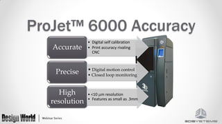
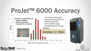
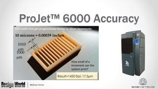
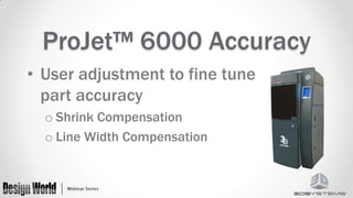
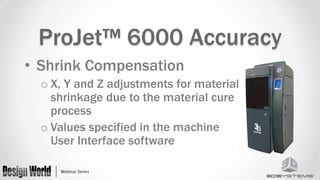
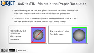
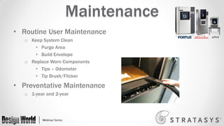
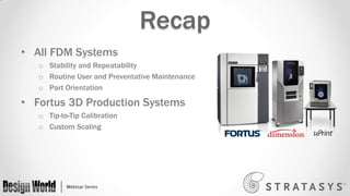
Tips for 3D
Printing Accuracy
Thank You to our Sponsors
Before We Start
This webinar will be available afterwards at
designworldonline.com & email
Q&A at the end of the presentation
Hashtag for this webinar: #DWwebinar
Moderator

Presenters

Leslie Langnau

Stacie Hoche

Ben Klein

Bonnie Meyer

Design World

3D Systems

Objet Ltd.

Stratasys
ProJet 6000 Accuracy
Stacie Hoche April 2012
ProJet™ 6000 Accuracy
Accurate
Precise
High
resolution

• Digital self calibration
• Print accuracy rivaling
CNC

• Digital motion control
• Closed loop monitoring

• <10 m resolution
• Features as small as .3mm
ProJet™ 6000 Accuracy
35

30

25

-- 3 x 3 matrix of test parts
-- 12 measurements per part
-- 108 measurements
-- 1mm to 32mm range
-- Standard Deviation of <15
microns

Accuracy is a combination of:
-- System capability
-- Material properties
-- Compared to an absolute

Frequency

20

15

10

5

Difference from nominal in microns

100

90

80

70

60

50

40

30

20

10

0

-10

-20

-30

-40

-50

-60

-70

-80

-90

-100

0
ProJet™ 6000 Accuracy
Thin walls that get progressively thicker in 10um increments

10 microns = 0.00039 inches
1010
m
1000
m
How small of a
increment can the
system print?

Result=1450 Dpi; 17.5m
ProJet™ 6000 Accuracy
• Machine Build Modes
o HD - Fastest
o UHD – General purpose build mode
o XHD – Fine feature detail
ProJet™ 6000 Accuracy
• User adjustment to fine tune
part accuracy
o Shrink Compensation
o Line Width Compensation
ProJet™ 6000 Accuracy
• Shrink Compensation
o X, Y and Z adjustments for material
shrinkage due to the material cure
process
o Values specified in the machine
User Interface software
ProJet™ 6000 Accuracy
• LineWidth Compensation
o Adjusts for the material cured line width
o Values very due to
• Print Head Characteristics
• Material
• Build Mode
o Values specified in the 3DManage setup
Software
ProJet™ 6000 Accuracy

Line-Width Compensation Off

Line-Width Compensation On
ProJet™ 6000 Accuracy
How to Obtain the Most Out of Your
Objet Printer: Quick Tips
CAD to STL - Maintain the Proper Resolution
• When creating an STL file, the goal is to achieve a balance between file
size and a fully-defined model with smooth curved geometries.

• You cannot build the model any better or smoother than the STL. So if
the STL is coarse and faceted, you will see it in the model.

Faceted STL file
translated
with coarse
tolerance

File translated with
fine tolerance
“Connexify” a Part
• Divide the CAD files into shells early in the design process
Non-Connex:
Monolithic part, one material

Connex: Assure a distinct separation between the solid bodies:
Create an assembly of one or more parts
“Connexify” a Part

Uncheck this to allow separate STL files
(For Connex)
Supporting Delicate Parts with Auxiliary Structures
In order to support fine features, an auxiliary part can be
printed and removed later

+

=
Matte Vs. Glossy
Matte mode is intended to generate uniform surfaces. Ensure your model is
suitable for this mode.
Objet Studio – Other Considerations
The visual differences between Matte and Glossy Parts
Accuracy in Appearance
To truly appreciate fine details on the surface, use VeroBlue or VeroGray
materials in the glossy orientation
Accuracy in Performance
To imitate final material performance, use Connex for complex applications
Fitting Surfaces
Fitting surfaces should be positioned facing up
No support material needs to be removed
Print Several Materials on a Single Piece
End part Shore value needs to be determined
Print Several Materials on a Single Piece
Connex Technology enables testing of different values on
a single print
Print Several Materials on a Single Piece
Accurate Parts with
FDM Systems
Bonnie Meyer, Sr. Applications Engineer
Stratasys, Inc.
All FDM Systems
 Thermoplastics are stable over days, months or years





ABS
Polycarbonate (PC)
Polyphenylsulfone (PPSF)
ULTEM
FDM – thorough analysis
 27 measurements
 12 parts per build

 3 runs per machine
 Repeated on 3 machines

108 sample parts
2916 measurements
FDM Repeatability
Results:
 σ: 0.0027 in. (0.07 mm)

 Mean: 0.00034 in. (0.009 mm)
Accuracy Over Time
Width
Nominal (3.000”,

Apr-2008
Actual

Aug-2011
Actual

Change over time

Sample 1

2.997”

2.997”

0.000” (0.00 mm)

Sample 2

3.001”

3.000”

-0.001” (0.03 mm)

Sample 3

2.999”

2.998”

-0.001” (0.03 mm)

Average

2.999”

2.998”

-0.001” (0.03 mm)

Length
Nominal (5.000”,

Apr-2008
Actual

Aug-2011
Actual

Change over time

Sample 1

4.999”

4.998”

-0.001” (0.03 mm)

Sample 2

4.998”

4.998”

-0.000” (0.00 mm)

Sample 3

4.998”

4.996”

-0.002” (0.05 mm)

Average

4.998”

4.997”

-0.001” (0.03 mm)

76.2 mm)

127 mm)
Maintenance
• Routine User Maintenance
o Keep System Clean
• Purge Area
• Build Envelope
o Replace Worn Components
• Tips – Odometer
• Tip Brush/Flicker

• Preventative Maintenance
o 1-year and 2-year
Orientation
• Critical Features
• Rounds
Calibration
• Tip Changes
• Periodically
Custom Scaling
• Fine Tune in X and Y if Needed
• Quantities of Parts
Recap
• All FDM Systems
o Stability and Repeatability
o Routine User and Preventative Maintenance
o Part Orientation

• Fortus 3D Production Systems
o Tip-to-Tip Calibration
o Custom Scaling
More Information
• www.stratasys.com/accuracy
o Download “Accuracy Myth” white paper
o Benchmark the process with your part

• Contact Stratasys Application Engineering
• 855-693-0073 (U.S. toll free)
• +1 952-294-3888 (local/international)
• ApplicationSupport@Stratasys.com
Questions?
Design World

3D Systems

Objet Ltd.

Stratasys

Leslie Langnau
llangnau@wtwhmedia.com
Phone: 440.234.4531
Twitter: @DW_RapidMFG

Ben Klein
Ben.Klein@objet.com
Phone: +1.972.52.889.2292

Stacie Hoche
Stacie.Hoche@3dsystems.com
Phone: 803.326.4613

Bonnie Meyer
Bonnie.Meyer@stratasys.com
Phone: 952.906.2244
Thank You
 This webinar will be available at designworldonline.com & email
 Tweet with hashtag #DWwebinar
 Connect with
 Twitter: @DesignWorld
 Facebook: facebook.com/engineeringexchange
 LinkedIn: Design World Group
 YouTube: youtube.com/designworldvideo

 Discuss this on EngineeringExchange.com
Tips for 3D Printing Accuracy

Tips for 3D Printing Accuracy

  • 1.
  • 2.
    Thank You toour Sponsors
  • 3.
    Before We Start Thiswebinar will be available afterwards at designworldonline.com & email Q&A at the end of the presentation Hashtag for this webinar: #DWwebinar
  • 4.
    Moderator Presenters Leslie Langnau Stacie Hoche BenKlein Bonnie Meyer Design World 3D Systems Objet Ltd. Stratasys
  • 5.
  • 6.
    ProJet™ 6000 Accuracy Accurate Precise High resolution •Digital self calibration • Print accuracy rivaling CNC • Digital motion control • Closed loop monitoring • <10 m resolution • Features as small as .3mm
  • 7.
    ProJet™ 6000 Accuracy 35 30 25 --3 x 3 matrix of test parts -- 12 measurements per part -- 108 measurements -- 1mm to 32mm range -- Standard Deviation of <15 microns Accuracy is a combination of: -- System capability -- Material properties -- Compared to an absolute Frequency 20 15 10 5 Difference from nominal in microns 100 90 80 70 60 50 40 30 20 10 0 -10 -20 -30 -40 -50 -60 -70 -80 -90 -100 0
  • 8.
    ProJet™ 6000 Accuracy Thinwalls that get progressively thicker in 10um increments 10 microns = 0.00039 inches 1010 m 1000 m How small of a increment can the system print? Result=1450 Dpi; 17.5m
  • 9.
    ProJet™ 6000 Accuracy •Machine Build Modes o HD - Fastest o UHD – General purpose build mode o XHD – Fine feature detail
  • 10.
    ProJet™ 6000 Accuracy •User adjustment to fine tune part accuracy o Shrink Compensation o Line Width Compensation
  • 11.
    ProJet™ 6000 Accuracy •Shrink Compensation o X, Y and Z adjustments for material shrinkage due to the material cure process o Values specified in the machine User Interface software
  • 12.
  • 13.
    ProJet™ 6000 Accuracy •LineWidth Compensation o Adjusts for the material cured line width o Values very due to • Print Head Characteristics • Material • Build Mode o Values specified in the 3DManage setup Software
  • 14.
    ProJet™ 6000 Accuracy Line-WidthCompensation Off Line-Width Compensation On
  • 15.
  • 16.
    How to Obtainthe Most Out of Your Objet Printer: Quick Tips
  • 17.
    CAD to STL- Maintain the Proper Resolution • When creating an STL file, the goal is to achieve a balance between file size and a fully-defined model with smooth curved geometries. • You cannot build the model any better or smoother than the STL. So if the STL is coarse and faceted, you will see it in the model. Faceted STL file translated with coarse tolerance File translated with fine tolerance
  • 18.
    “Connexify” a Part •Divide the CAD files into shells early in the design process Non-Connex: Monolithic part, one material Connex: Assure a distinct separation between the solid bodies: Create an assembly of one or more parts
  • 19.
    “Connexify” a Part Uncheckthis to allow separate STL files (For Connex)
  • 20.
    Supporting Delicate Partswith Auxiliary Structures In order to support fine features, an auxiliary part can be printed and removed later + =
  • 21.
    Matte Vs. Glossy Mattemode is intended to generate uniform surfaces. Ensure your model is suitable for this mode.
  • 22.
    Objet Studio –Other Considerations The visual differences between Matte and Glossy Parts
  • 23.
    Accuracy in Appearance Totruly appreciate fine details on the surface, use VeroBlue or VeroGray materials in the glossy orientation
  • 24.
    Accuracy in Performance Toimitate final material performance, use Connex for complex applications
  • 25.
    Fitting Surfaces Fitting surfacesshould be positioned facing up No support material needs to be removed
  • 26.
    Print Several Materialson a Single Piece End part Shore value needs to be determined
  • 27.
    Print Several Materialson a Single Piece Connex Technology enables testing of different values on a single print
  • 28.
    Print Several Materialson a Single Piece
  • 29.
    Accurate Parts with FDMSystems Bonnie Meyer, Sr. Applications Engineer Stratasys, Inc.
  • 31.
    All FDM Systems Thermoplastics are stable over days, months or years     ABS Polycarbonate (PC) Polyphenylsulfone (PPSF) ULTEM
  • 32.
    FDM – thoroughanalysis  27 measurements  12 parts per build  3 runs per machine  Repeated on 3 machines 108 sample parts 2916 measurements
  • 33.
    FDM Repeatability Results:  σ:0.0027 in. (0.07 mm)  Mean: 0.00034 in. (0.009 mm)
  • 34.
    Accuracy Over Time Width Nominal(3.000”, Apr-2008 Actual Aug-2011 Actual Change over time Sample 1 2.997” 2.997” 0.000” (0.00 mm) Sample 2 3.001” 3.000” -0.001” (0.03 mm) Sample 3 2.999” 2.998” -0.001” (0.03 mm) Average 2.999” 2.998” -0.001” (0.03 mm) Length Nominal (5.000”, Apr-2008 Actual Aug-2011 Actual Change over time Sample 1 4.999” 4.998” -0.001” (0.03 mm) Sample 2 4.998” 4.998” -0.000” (0.00 mm) Sample 3 4.998” 4.996” -0.002” (0.05 mm) Average 4.998” 4.997” -0.001” (0.03 mm) 76.2 mm) 127 mm)
  • 35.
    Maintenance • Routine UserMaintenance o Keep System Clean • Purge Area • Build Envelope o Replace Worn Components • Tips – Odometer • Tip Brush/Flicker • Preventative Maintenance o 1-year and 2-year
  • 36.
  • 37.
  • 38.
    Custom Scaling • FineTune in X and Y if Needed • Quantities of Parts
  • 39.
    Recap • All FDMSystems o Stability and Repeatability o Routine User and Preventative Maintenance o Part Orientation • Fortus 3D Production Systems o Tip-to-Tip Calibration o Custom Scaling
  • 40.
    More Information • www.stratasys.com/accuracy oDownload “Accuracy Myth” white paper o Benchmark the process with your part • Contact Stratasys Application Engineering • 855-693-0073 (U.S. toll free) • +1 952-294-3888 (local/international) • ApplicationSupport@Stratasys.com
  • 41.
    Questions? Design World 3D Systems ObjetLtd. Stratasys Leslie Langnau llangnau@wtwhmedia.com Phone: 440.234.4531 Twitter: @DW_RapidMFG Ben Klein Ben.Klein@objet.com Phone: +1.972.52.889.2292 Stacie Hoche Stacie.Hoche@3dsystems.com Phone: 803.326.4613 Bonnie Meyer Bonnie.Meyer@stratasys.com Phone: 952.906.2244
  • 42.
    Thank You  Thiswebinar will be available at designworldonline.com & email  Tweet with hashtag #DWwebinar  Connect with  Twitter: @DesignWorld  Facebook: facebook.com/engineeringexchange  LinkedIn: Design World Group  YouTube: youtube.com/designworldvideo  Discuss this on EngineeringExchange.com