Download to read offline
![1
and
Aerospace Engineering
Ashby Building
Stranmillis Road
Belfast
BT9 5AH
Mechanical and Aerospace Engineering
Final Year Project Technical Report
Project 3B
AER3021
Fabrication and Characterization of Novel Boron Nitride/Polymer nanocomposite
Author: Sayed Asif Iqbal [40110295]
Project Supervisor: Dr Dan Sun
Programme: BEng Aerospace Engineering
Date: 18th
March 2016](https://image.slidesharecdn.com/990f323f-404a-4cc1-94d7-74ab7182a12f-161116042129/85/HDPEnanocomposite-1-320.jpg)
![1
and
Aerospace Engineering
Ashby Building
Stranmillis Road
Belfast
BT9 5AH
Mechanical and Aerospace Engineering
Final Year Project Technical Report
Project 3B
AER3021
Fabrication and Characterization of Novel Boron Nitride/Polymer nanocomposite
Author: Sayed Asif Iqbal [40110295]
Project Supervisor: Dr Dan Sun
Programme: BEng Aerospace Engineering
Date: 18th
March 2016](https://image.slidesharecdn.com/990f323f-404a-4cc1-94d7-74ab7182a12f-161116042129/75/HDPEnanocomposite-1-2048.jpg)

![4
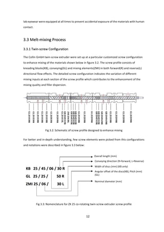
1.0 Introduction
Polymers, according to Oxford Dictionary, are simply the combinations of small simple molecules
grouped together in a chain-like order to form large and long groups of atoms. The word ‘polymer’
was first coined by a Swedish chemist called ‘Jöns Jacob Berzelius’ in 1832 [1] and later established
by a German chemist named ‘Hermann Staudinger’ in 1905 [2]. The beauty behind the sciences of
such ‘macromolecules’ intrigued the chemists from the very start of 1900s. With later discoveries
in the progression of time, it was quite surprising to find out that polymers existed all around and
within us. Macro molecules are found to be present by far and wide, from the food we eat which
contains starch or proteins, to the very bits of DNA strands inside our infinitesimal body cells [3].
These naturally occurring polymers emerged after pursuits of tremendous studies conducted to
interpret material sciences and biophysics. From the data gathered from these studies to the in-
depth understanding- all these lead to the evolution of synthetic polymers, and now it is nearly
impossible to imagine our world without them. Understanding these useful macro molecules have
enabled us to customize and alter their structures to achieve composite materials with desired
properties relevant to its use. Greatest evidences will include usage of ‘para-aramid’ in bulletproof
and waterproof vests, ‘meta-aramid’ in the hood of fire-fighter’s mask, ‘copolyamid’ in fiber optic
cables and many more [4]. To get the most out of these materials and to make our lives easier, two
or more different materials are blended in an effort to accomplish the best properties of both. Such
nanocomposite materials with at least one component of nanoscopic scale in size (10-9
m) have
remarkable properties like high surface to volume ratio, increased ductility and are scratch
resistant, and so on. [5].
This project is about fabrication and characterization of Boron nitrite/high density polyethylene
nanocomposites. Along with a comprehensive research for the understanding of the structure and
properties of these materials, the project will also reflect and unfold the industrially relevant
polymer processing technique called "extrusion". Different proportions of boron nitrite powders,
ordered from SIGMA-ALDRICH, will be melt-mixed with high density polyethylene pallets under
twin-screw extrusion process. Suitable composite samples will be extracted from the extruded
sheet and appropriate testing methods standards will be identified. Samples will also be stretched
in the uniaxial direction to scrutinize material behavior exposed to different test conditions.
Moreover, these samples will be tested using different engineering equipment and detailed](https://image.slidesharecdn.com/990f323f-404a-4cc1-94d7-74ab7182a12f-161116042129/85/HDPEnanocomposite-4-320.jpg)
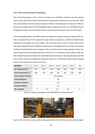
![5
comparisons will be obtained and investigated. Result analysis will later be discussed to provide
better reasoning and understanding of the micro structural behavior.
2.0 Literature Review
2.1 BN Nanofillers
After the evolution of Rubber technology at roughly 1800s, synthetic polymers started being
fabricated and just prior to world war II, this industry started to grow introducing different arrays
of materials referred to as ‘Plastics’. These pallets or powders are produced by mechanical blending
or melt state mixing procedures [6]. Boron nitride nanocomposites, a structural analogue of carbon
precursors, were first fabricated at the late 90s. Instead of carbon atoms linked in chains, boron
and nitrogen atoms are joined up alternatively [7]. With at least one dimension in between the
scale of 1 to 100 nanometers, these extraordinary and flexible forms of nanostructures can be
formed into various structural arrangements e.g. nanotubes, nanosheets, nanohorns, spherical
nanoparticles, etc[ 8].
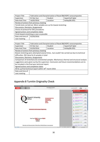
Fig 2.1: TEM image of BN Nanosheets
The layered nature and planar networks between the BN hexagons allow such flexibility to produce
nanosized BN which is much superior in various properties compared to the traditional microsized
BN fabricated years ago. BN nanostructures are equipped with novel properties intrinsically which](https://image.slidesharecdn.com/990f323f-404a-4cc1-94d7-74ab7182a12f-161116042129/85/HDPEnanocomposite-5-320.jpg)
![6
includes wider bandgap up to 6 eV, anti-oxidation and structural ability, high thermal conductivity
and great mechanical properties [8]. In contrast with the aforementioned attributes which are quite
similar to corresponding carbon materials, boron nitride analogues possess several unique features
that makes them quite significant in modern world. These structures, unlike carbon
nanocomposites, are white or transparent in color due to its wide bandgap so can be dyed
depending on different requirements [8]. Moreover, the carbon precursors are observed to lower
the electrical insulation of polymers, whereas BN nanostructures are dielectric in nature that
strengthen its use as gate layers and remarkable use in electronic packaging. In recent years,
nanosized BN as shown in figure 2.1 are produced with very high aspect ratio, thermal conductivity
up to thousands of Wm-1
K-1
(when used as nanofillers) and tremendous material strength [8].
2.2 BN Nanofillers in contrast with Carbon precursors
BN nanosheets are comprised of one or few layers of hexagonal boron nitride (h-BN). After the rise
of Graphene in the year of 2005, the first pure monolayer h-BN was originated in a mechanically
milled residue[9]. So far, various methods are implemented including ball milling [11], mechanical
cleavage [10], the reaction between boric acid and urea[13-14] and high energy electron beam
irradiation [12]. Ultrathin nanosheets are produced from chemical vapor disposition (CVD) method
[9]. Whereas the ‘chemical blowing’ method is considered to be the simplest of all due to its catalyst
and substrate-free route [9]. Besides, it not only gives the luxury to obtain larger lateral dimensions
of BN nanosheets that aids research to be carried out regarding its electrical and mechanical
behaviors, but also can be used later on to produce strong polymer composites [9]. The CVD
method is widely used to produce both BN nanosheets and nanotubes: one or few layers of BN
sheets rolled up to nanoscale. Figure 2.1 represents a brief tabular comparison between graphene,
BNNSs, CNT and BNNTs [8]:](https://image.slidesharecdn.com/990f323f-404a-4cc1-94d7-74ab7182a12f-161116042129/85/HDPEnanocomposite-6-320.jpg)
![7
Fig 2.2: Comparison between graphene, BNNSs, CNT and BNNTs properties in different fields in a
nutshell [8].
2.3 Polymer processing Techniques
In the plastic processing industry, injection moulding is widely used to process polymer composites
due to its cost-effective way of processing three-dimensional and complex thermoplastics at
greater quantities [16]. However, the parts and equipment like hopper, feed throat, barrel, etc. are
expensive to maintain and it’s costly to operate the machine as well. With series of procedures,
polymers are processed via injection moulding. The plastic pallets are fed to the injection unit
where it is heated by the barrel and melted the by the sheer force of the revolving screw. Later the
melted polymers are pushed into the mould section where the shape of the plastic is altered by
heating and cooling in various different ways. Other moulding techniques like blow and rotational
moulding are also used.
Techniques like extrusion and injection moulding are worth mentioning. Conventional extrusion
processes are material intensive techniques where the polymers are manipulated in molten
state[6]. This is considered as the state of the art technique till date because it is specialized to
produce final product from raw polymers. The mechanism is quite simple where the nanofillers are
dispersed into the polymer matrix by melt mixing [6]. An archetypal extruder can be of two types:
single screw and twin screw extruder. Both extrusion processes have horizontal barrels with
adjustable temperature cores, a hopper to collect the raw materials, extruder and die section. Raw](https://image.slidesharecdn.com/990f323f-404a-4cc1-94d7-74ab7182a12f-161116042129/85/HDPEnanocomposite-7-320.jpg)
![8
materials are taken down and then crushed and melted by the rotating screw(s) in the extruder,
thus dispersing the additives into the polymer matrix [17]. The final products then exit through the
end of the barrel or die section. The screw speed is alterable to maintain smooth mixing and
dispersion into the polymer matrix, even if the melt solution gets too viscous due to more addition
of nanofillers[18].
The screw(s) inside the barrel play(s) crucial role in mixing the raw materials. Single-screw extrusion
process implies the barrel containing one screw rotating only in order to blend the raw polymers in
few different stages. The screw, when analyzed, is seen to have different depths along its length
and can be classified into three sections carrying out different functions in each region. The feed
section screw will simply rotate and take up the raw materials into the compression section which
has lesser screw depth [18]. This change in depth not only allows to apply pressure and compress
the polymers, but also squeezes the air bubble and send them back to the previous section of the
rotating screw. The polymers are sharply and gradually melt mixed and then conveyed to the meter
section where the screw depth is lowest and is constant throughout the section. Temperature in
each section will differ throughout the process to depending on the melt characteristics of the
materials. The metering screw zone will homogenize the melt until fed to the die section which has
constant temperature and pressure conditions [19]. Moreover, the die section will filter and
separate by getting rid of extraneous material and letting the expected product polymer to extrude
out.
For twin-screw extrusion system, two screws are rotated in different syntaxes to serve the purpose.
The two collaborating screws can be positioned into four types of screw systems including co-
rotating/counter-rotating intermeshed and co-rotating/counter rotating non-intermeshed. For
intermeshing screws attached together, flow patterns are not allowed to pass in-between the
screws. But for non-intermeshing arrangements small clearance is observed where the flow
patterns are compared with the figure-of-eight [18]. Operation variables like heat generation and
mixing efficiency are enhanced to get optimized outputs.
2.4 Dispersion of Nanofillers into Polymer matrix
As far as dispersing nanofillers into polymer matrix are concerned, dispersion properties or types
depend directly on the shear forces exerted by the screw(s) system. Two types of dispersion are
listed as dispersive and distributive mixing. Dispersive mixing is concerned with the process where](https://image.slidesharecdn.com/990f323f-404a-4cc1-94d7-74ab7182a12f-161116042129/85/HDPEnanocomposite-8-320.jpg)
![9
the screws exert high shear forces which breaks large clusters into small ones by overcoming
interacting forces and dispersing them throughout the solution. Whereas distributive mixing, on
the other hand, is referred to take place in a low shear exertion system where the weak forces
interacting between the nanofillers, distributing them uniformly through the melt. Screw
geometries are responsible for the amount of shear force exerted to the mixture which, therefore
high shear forces are crucial to achieve dispersive mixing. However, high shear forces are
responsible for breaking the clusters into finer ones, but this type of flow is not enough as we are
required to disperse the nanofillers as well. Applying high shear forces by altering screw geometries
is only half the job done, other main flow type is solely required referred to as elongation plays a
great role in uniform dispersion [20]. Higher extensional elongation can be applied to the
nanoparticles in the polymer melt in the twin screw extrusion process. It is also observed that high
screw speed and longer mixing time is the key to better morphology of the nanocomposites
obtained.
2.5 Post-extrusion stretching
Biaxial and uniaxial stretching takes place in the extrusion process where the nanoparticles and the
polymer while in melt state. Not only that during post processing, a sample cut from the extruded
sheet can be taken and stretched in solid state in one or both direction in the x, y plane. It is
significant to observe that the post-extrusion stretched nanocomposites had different properties
compared to that of un-stretched ones. In a research carried out by the School of Aerospace and
Mechanical Engineering, QUB on biaxial stretching [21] of polymer nanocomposites, novel
enhanced properties were observed. With a temperature between 145-150 degrees being set up,
a 76mm×76mm×1mm compression moulded sheet of PET/clay nanocomposite is biaxially
stretched at 1.5, 2.5, 3 and 3.5 stretching ratios and loaded at the strain rate of 8 and 16s-1. Each
test were repeated twice to get a better approximation of the results. The forces and displacement
at x, y plane were recorded by the help of Labview Data Logging Package. Looking at the results, it
concludes that higher strain rates were driving a higher yield stress of the sample [21]. Moreover,
addition of clay as a filler were contributing to greater entanglement of the molecules. Higher yield
stress at lower temperature was also observed as nanofilled composite materials are more sensitive
to temperature. Under X-ray diffraction (XRD) analysis, it is monitored that the d-spacing in the
PET/clay lattice is noted to reduce at the strain rate of 1.5. Besides, the d-spacing slightly increased
with higher strain rates which was still lower than that of the unstretched sheet. So this overall
decrease took place because of the compression of the clay particles (nanofillers) due to stretching](https://image.slidesharecdn.com/990f323f-404a-4cc1-94d7-74ab7182a12f-161116042129/85/HDPEnanocomposite-9-320.jpg)
![10
[21].
In TEM analysis, the stretched and unstretched samples are compared under ultrahigh
magnification where it is observed that on stretching it is evident that the delamination of
nanofillers were resulting to stack up and align the particles. Differential Scanning Calorimetry (DSC)
were used to examine the crystallinity of the test sample. It was observed that the crystallinity was
increasing with higher strain rates but it also concluded that greater crystallinity doesn’t contribute
to higher mechanical strength [21]. It is also seen that the tensile strength only increases, when the
sample is stretched and the highest strength is achieved at the highest strain rate of 3.5, also giving
rise to the break stress. This is described and associated with the better unity of the polymer due
to temperature application and stress exertion. It is also very important to notice that the effect on
modulus is not observed until the sample was stretched up to SR 2.5. This happens because the
degree of alignment of the molecules are only articulated at this very stage. This rate might differ
from different starting material to form the nanocomposite [21].
Unlike biaxial stretching, uniaxial stretching is similar but the sample is either stretched along the
length or perpendicular to the length. In terms of uniaxial stretching, equipment like two
dimensional wide angle x-ray scattering (2D-WAXS) fit to serve the purpose to characterize the
sample after it is stretched. DSC is also used in biaxial stretching characterization. The process is
quite similar to biaxial stretching as the sample is uniformly heated and but stretched at one
direction only. Hence by the help of all state of the art equipment, like WAXS and DSC, the sample
uniaxial stretched sample is characterized in terms of thermal or mechanical strengths.](https://image.slidesharecdn.com/990f323f-404a-4cc1-94d7-74ab7182a12f-161116042129/85/HDPEnanocomposite-10-320.jpg)
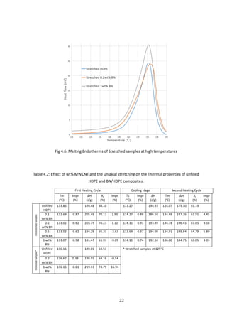
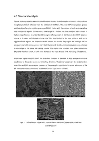
![16
typical mass of only 7-10mg, followed by sealing them inside small aluminum pans and lids by
crimping them in the press. The inner and outer lids of the DSC furnace were removed to place the
sealed sample on the left sample pan. The furnace lids were replaced back and the equipment were
set up to raise the temperature of the furnace from 30°C to 200°C at a pace 10°C/min for both
stretched and unstretched samples. Furthermore, the unstretched samples were held at 200°C for
3 minutes and cooled down to 30°C at the same rate of 10°C/min and heated back to 200°C again
using the same gradient trend mentioned above to check the bulk properties have changed
fundamentally or not. Stretched samples were not checked for bulk property changes because they
were already heated again while stretching under elevated temperature conditions. The apparent
percentage crystallinity of the content is measured using the formula below:
% 𝑐𝑟𝑦𝑠𝑡𝑎𝑙𝑙𝑖𝑛𝑖𝑡𝑦 =
𝑚𝑒𝑎𝑠𝑢𝑟𝑒𝑑 ∆𝐻
100% 𝑐𝑟𝑦𝑠𝑡𝑎𝑙 ∆𝐻
×100
∆𝐻 = 𝐻𝑒𝑎𝑡 𝑜𝑓 𝑓𝑢𝑠𝑖𝑜𝑛
100% 𝑐𝑟𝑦𝑠𝑡𝑎𝑙 ∆𝐻 = 293 J/g [22]
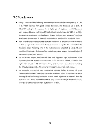
3.4.3 Structural Analysis
The structure of the samples and the degree of dispersion of the BN fillers into the HDPE matrix
were investigated using Scanning Electron Microscopy (SEM). Reactive ion etching system were
used to plasma etch the samples. This high speed plasma glow discharge is shot at the samples for
60 s and at the power of 100w and then gold coated or sputtered prior to imaging. Joel 6500 Field
Emission Scanning Electron Microscopy were used with operating voltages of 3 and 5 kV to
examine the samples.
4.0 Results and Discussion
4.1 Mechanical Analysis
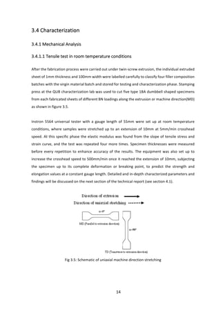
Dog bone-shaped samples were stretched as mention previously and tensile tests were carried out
at room temperature conditions. Five samples were tested till breaking stress were applied and
average young’s modulus and yield stress values were extracted from the Instron data logging
package. Figure 4.1 provides the variation of tensile modulus and yield stress values with different
composition of boron nitride fillers used during fabrication process.](https://image.slidesharecdn.com/990f323f-404a-4cc1-94d7-74ab7182a12f-161116042129/85/HDPEnanocomposite-16-320.jpg)
![18
the stress level at which the filled polymers ceased to behave elastically decreased with higher filler
composition, probably due to creation of microvoids resulting from phase separation of BN/HDPE
interface [23]. This can also result from lesser restriction on molecular mobility or decreased
entanglement of molecules.
By increasing the crosshead speed to 500mm/min the samples were also examined to detect
mechanical behavior in complete deformation process. The breaking stress is discovered to
increase till 0.1 and 0.2 wt% BN with contrasting value drops at other two higher BN compositions.
This might be attributed to the structural orientation of the molecules and non-uniform filler
dispersion on higher BN loadings. On the other hand, strain to failure percentage data on different
filler composition is scrutinized to show very low fluctuations except 0.1 wt% BN. The bar charts
below depict the breaking stress and strain fluctuations:
Fig 4.2: Effect of addition of BN fillers on breaking stress and strain values
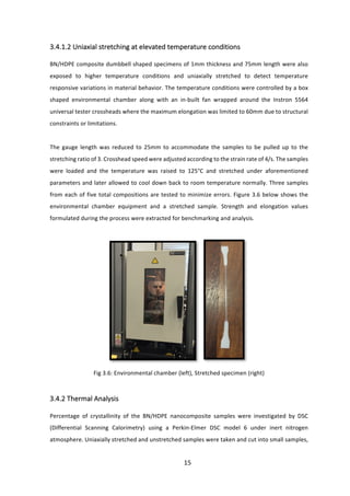
Its is very vital to note that all these aforementioned tensile tests were carried out under normal
room temperature conditions. On the other hand, samples were also subjected to elevated
temperature condition of 125°C by stretching them up to the ratio of three and strain rate of 4/s.
With respect to the tensile test carried out at room temperature, both Young’s modulus and yield
stresses are observed to decrease in high magnitudes with high temperature conditions. Both the
filler and polymer matrix materials are observed to be highly responsive to temperature and strain
rates while stretched and the parameters used in both scenarios are very different from each other
that generated such significant variation in the extracted values presented at figure 4.3 below:](https://image.slidesharecdn.com/990f323f-404a-4cc1-94d7-74ab7182a12f-161116042129/85/HDPEnanocomposite-18-320.jpg)
![20
4.2 Thermal Analysis
For DSC examination, the stretched and unstretched samples were taken up and tested to measure
percentage crystallinity of five different BN loadings for unstretched and three BN composition for
stretched samples. Melting and crystallization behavior for these samples were extracted and
presented in figure 4.4. The thermograms of the unstretched samples are compared within
different phases that refers to the first heating cycle, cooling down in the same rate and heating
again for second time to delete thermal history and to check if the bulk polymer may have changed
fundamentally or not.
It is clearly visible on figure 4.4 that the crystallization endotherms have changed its shape with
increasing BN filler addition as the crystallization peaks get wider due to the change in crystal type
and perfection. This can happen because less perfect crystallites melt partially at low temperatures
making the average crystal shape larger [24]. And at higher temperatures the molecular chains are
more mobile producing more crystallites and making the average crystal size smaller. These
recrystallized crystallites are also detected to have higher melting peaks corresponding to higher
BN loadings due to the formation of more perfect crystals with greater dimensions and lesser
deformity.
Fig 4.4: Crystallization exotherms of unstretched samples
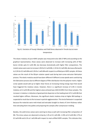
The addition of BN have contributed to slight improvement in percentage crystallinity with respect
to the unfilled neat HDPE. Highest improvement in crystallinity for unstretched samples are found
to be 67.05% for 0.2 wt% BN loading which enhanced the unfilled HDPE up to 9.58%. At higher filler](https://image.slidesharecdn.com/990f323f-404a-4cc1-94d7-74ab7182a12f-161116042129/85/HDPEnanocomposite-20-320.jpg)
![21
composition the enhancements are found to be a bit upsetting as higher loadings of 0.5 and 1 wt%
BN did improve the crystallinity with respect to neat HDPE but reduced with respect to unstretched
0.2 wt% BN samples. This explains that at higher BN loadings, it is relatively difficult to disperse the
fillers into the polymer matrix during melt-mixing. Higher screw speeds might have been required
to enhance mixing and enhance the availability of nucleating sites for HDPE crystallization [25].
Fig 4.5: Comparison of melting endotherms with first and second stage heating
Other set of stretched samples are only tested for first heating cycle as they have already been
subjected to higher temperature during uniaxial stretching. The generated endotherms are found
to be potent and narrower, implying that the uniaxial stretching has contributed to more ordered
and synchronized crystallite patterns. Addition of BN and stretching barely affected the melting
temperature. It is also important to note that, the highest enhancement in percentage crystallinity
is found in stretched 1wt% BN samples where it is calculated out to be 15.94% higher than the
unfilled stretched sample (see Table 4.2 and Figure 4.6). Moreover, a contrasting behavior can be
pointed out if compared to the unstretched material of same BN loading of 1wt%. Moreover, the
crystallinity content increased by 18.6% higher due to stretching at higher temperature condition
that helped the molecular chains to align in a better orientation with the fillers. Percentage
crystallization Xc of unfilled HDPE were measured to be about 61.2% that raised to 63.9% with an
addition of 1wt% BN, which further increased to 74.8% after being stretched uniaxially at 125°C.
This undoubtedly indicates that both BN nucleated and strain induced HDPE crystallization has
contributed to the higher crystallization content achieved.](https://image.slidesharecdn.com/990f323f-404a-4cc1-94d7-74ab7182a12f-161116042129/85/HDPEnanocomposite-21-320.jpg)


The document is a technical report on the fabrication and characterization of novel boron nitride/polymer nanocomposites. It describes how boron nitride nanoparticles were melt-mixed with high density polyethylene using a twin-screw extrusion process. The nanocomposites were then characterized through various mechanical, thermal, and structural tests. The results from the tensile tests, thermal analysis, and structural analysis are presented and discussed to better understand the microstructural behavior of the novel nanocomposites.


![النسخة_النهائية_اطروحة_الدكتوراه_انوار_قاسم_سعيد_369[1].pdf](https://cdn.slidesharecdn.com/ss_thumbnails/3691-251113074443-2f6afba6-thumbnail.jpg?width=640&height=640&fit=bounds)


