Download to read offline
![International Research Journal of Engineering and Technology (IRJET) e-ISSN: 2395-0056
Volume: 06 Issue: 04 | Apr 2019 www.irjet.net p-ISSN: 2395-0072
© 2019, IRJET | Impact Factor value: 7.211 | ISO 9001:2008 Certified Journal | Page 1474
4. Noise shells;
5. Manifold errors.
A step in the STL generation known as "repair" fixes such
problems in the original model. Generally STLs that have
been produced from a model obtained through 3D
scanning often have more of these errors. This is due to how
3D scanning works-as it is often by point to pointacquisition,
reconstruction will include errors in most cases.
C. Finishing
Fig-3: Finishing of specimen
Thoughtheprinter-producedresolutionissufficientformany
applications, printing a slightly oversized version of the
desired object in standard resolution and then removing
material with a higher-resolution subtractive process can
achieve greater precision.
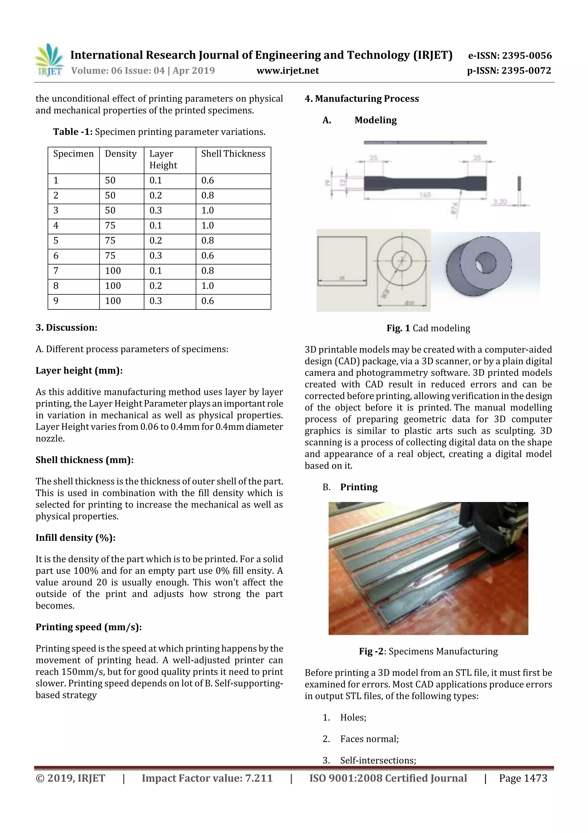
5. Design of Experiments.
A. Taguchi DOE:
Taguchi design, or an orthogonal array, is a method of
designing experiments thatusuallyrequiresonlyafractionof
the full factorial combinations. An orthogonal array means
the design is balanced so that factor levels are weighted
equally. Because of this, each factor can be evaluated
independently of all the other factors, so the effect of one
factor does not influence the estimation of another factor.
Dr.Genichi Taguchi is regarded as the foremost proponent of
robust parameter design, which is anengineeringmethodfor
product or process design that focuses on minimizing
variation and/or sensitivity to noise.
B. Taguchi Method
In the optimization of 3D printer there are THREE
Parameters (Factors) THREE Levels.
For Full Factorial method the number of
experiments is 27.
For Taguchi Method for THREE factors THREE
levels.
For maximization of Tensile Strength.
For maximization of Strength (Hardness).
For Larger -the-Better
S/FL=-10log10 [⅀ (1/y2)/n]
For minimization of Surface Roughness
For Smaller-the-Better
S/FS=-10log10 [(⅀y2)/n]
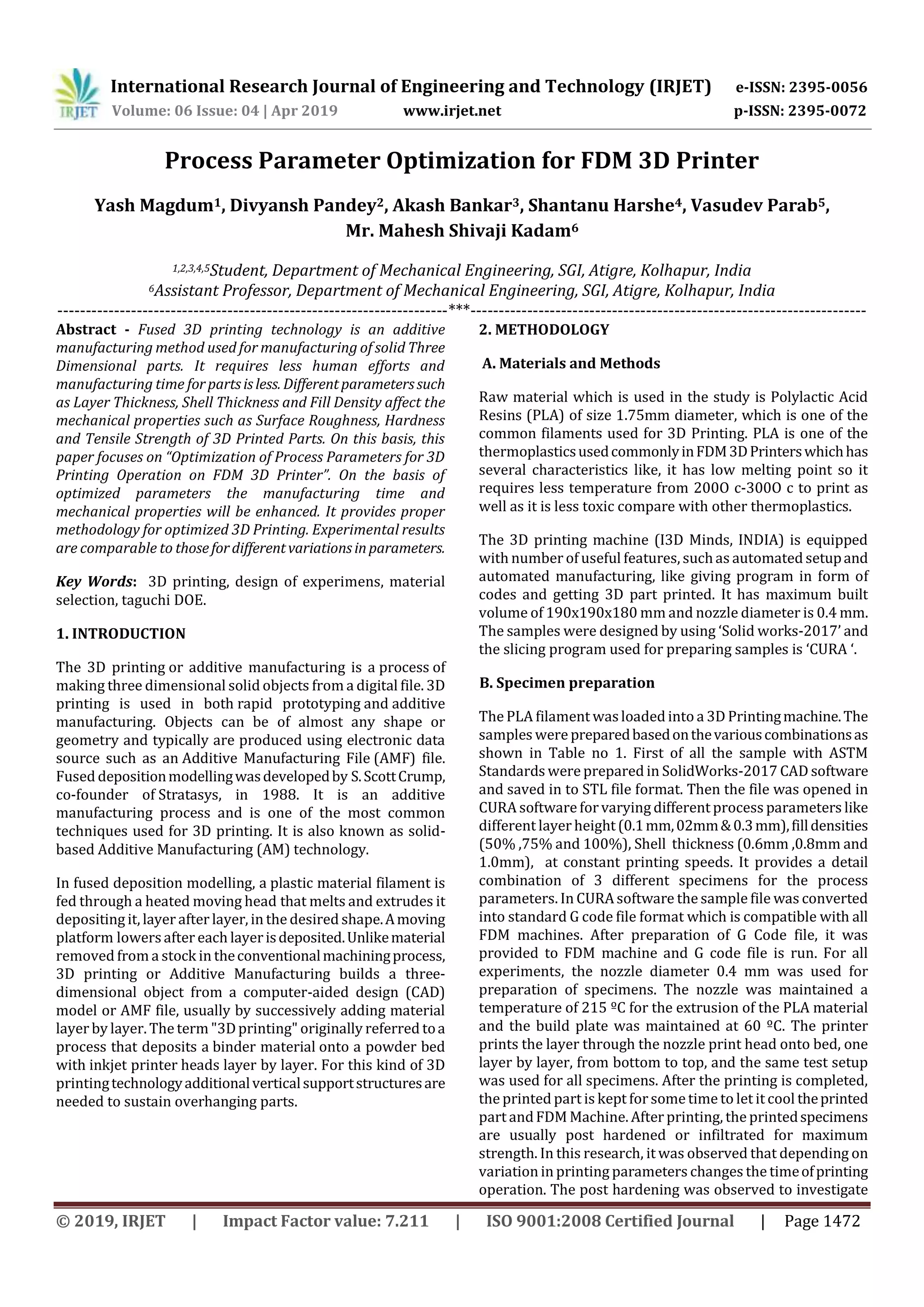
Table -2: No. of parameters and levels.
Factors Levels
1 2 3
Fill Density 50 75 100
Layer Thickness 0.1 0.2 0.3
Shell Thickness 0.6 0.8 1.0
Table -3: Experiment no. and Control Factors.
Experiment
No.
Control Factors
A B C
1 1 1 1
2 1 2 2
3 1 3 3
4 2 1 3
5 2 2 1
6 2 3 2
7 3 1 2
8 3 2 3
9 3 3 1
6. Testing Techniques
A. Tensile Test
Fig-4: Universal Testing Machine](https://image.slidesharecdn.com/irjet-v6i4313-190626084037/75/IRJET-Process-Parameter-Optimization-for-FDM-3D-Printer-3-2048.jpg)

![International Research Journal of Engineering and Technology (IRJET) e-ISSN: 2395-0056
Volume: 06 Issue: 04 | Apr 2019 www.irjet.net p-ISSN: 2395-0072
© 2019, IRJET | Impact Factor value: 7.211 | ISO 9001:2008 Certified Journal | Page 1476
FEATURES
• The 2.4-inch colour graphic LCD provides excellent
readability and an intuitive display that is easy to use. The
LCD also includes a backlight for improved visibility in dark
environments.
• The Mititoyo SJ-210 can be easily operated using the
buttons on the front of the unit and under the sliding cover.
• Up to 10 measurementconditionsandonemeasuredprofile
can be stored in the internal memory.
• An optional memory card can be used as an extended
memory to store large quantities of measured profiles and
conditions. Access to each featurecanbepasswordprotected
which prevents unintended operations and allows you to
protect your settings.
• The display interface supports 16 languages, which can be
freely switched.
• An alarm warns you when the cumulative measurement
distance exceeds a preset limit.
• The Mititoyo SJ-210 complies with the followingstandards:
JIS (JIS-B0601-2001,
JIS-B0601-1994, JIS B0601-1982), VDA, ISO-1997 and ANSI.
• In addition to calculation results, the Mititoyo SJ-210 can
display sectional calculation results and assessed profiles,
load curves, and amplitude distribution curves.
7. CONCLUSION
On the basis of varying differentparametersindifferentlevel
a Design of Experiments are carried out which can be used
for preparation of specimens for optimization of 3D printed
products for different parameters of 3D printing. Testing
machines are selectedfortestingmechanical propertiessuch
as Tensile strength, Hardness and Surface Roughness of 3D
printed specimens.
REFERENCES
[1] Elizabeth Matias, Bharat Rao, 3D Printing: On Its
Historical Evolution and the Implications for Business,
PICMET '15: ManagementoftheTechnologyAge,(2015)
(Pg.551-558)
[2] Dina R. Howeidy , The Impact of Using 3D Printing on
Model Making Quality and Cost in the Architectural
Design Projects, International Journal of Applied
Engineering Research ISSN 0973-4562 Volume 12,
(2017) (pg.987-994).
[3] Mamta Junejaa, Niharika Thakura, Dinesh Kumara,
Ankur Guptab, Babandeep Bajwac, Accuracy in dental
surgical guide fabrication using different 3-D printing
techniques, Additive Manufacturing, (2018), (Pg.243-
255).
[4] Barry Berman, 3-D printing: The new industrial
revolution, KelleySchool ofBusiness,Indiana University.
All rights reserved, (2011) (Pg.155-162).
[5] Wei Dai Vian, PhD and Nancy L. Denton, Hardness
Comparison of Polymer Specimens Produced with
Different Processes , PE School of Engineering
Technology Purdue University Kokomo and West
Lafayette, Indiana, (2015) (Pg.1312-1314).
[6] Wenyong Liu, Ying Li, Jinyu Liu, Xufeng Niu, Yu Wang
and Deyu Li, ApplicationandPerformanceof3DPrinting
in Nanobiomaterials, Key Laboratory for Biomechanic
sand Mechanobiology of MinistryofEducation, School of
Biological Science and Medical Engineering,
BeihangUniversity,Beijing100191,China,(2014)(Pg.1-7)
[7] Nathaniel Hudson1, Celena Alcock2, Parmit K. Chilana1,
Understanding Newcomers to 3D Printing: Motivations,
Workflows, and Barriers of Casual Makers ,
1Management Sciences University of Waterloo
Waterloo, ON Canada {ndphudso,pchilana}2Drama and
Speech Communication University of Waterloo
Waterloo, ON Canada(2016)(Pg. 384-396)
[8] Yingying Xuea, Xinfu Wanga, Wen Wanga, Xiaokang
Zhonga, Fusheng Hana,Compressive property of Al-
based auxetic lattice structures fabricated by 3D
printing combined with investment casting, aKey
Laboratory of Materials Physics, Institute of Solid State
Physics, Chinese Academy of Sciences, Hefei, Anhui
230031, China bUniversity of ScienceandTechnologyof
China, Hefei, Anhui 230026, China(2018)(255-262)
[9] Chelsea Schelly, GeraldAnzalone, BasWijnen,
JoshuaM.Pearce , Open-source3-Dprintingtechnologies
for education: Bringing additive manufacturing to the
classroom,(2015)(Pg. 1-12)
[10] Nadim S. Hmeidat, James W. Kemp, Brett G. Compton,
High-strength epoxy nanocomposites for 3D printing,
Mechanical, Aerospace, and Biomedical Engineering
Department University of Tennessee, Knoxville
Knoxville, TN 37996 USA, (2018)(1-36)
[11] Wei Dai Vian, PhD and Nancy L. Denton, Hardness
Comparison of Polymer Specimens Produced with
Different Processes, School of Engineering Technology
Purdue University Kokomo and WestLafayette,Indiana,
(2018)
[12] Daniel Farbman, Material Testing of 3D PrintedABSand
PLA Samples To Guide Mechanical Design, University of
California, BerkeleyBerkeley,California,UnitedStatesof
America, (2017)(1-12)](https://image.slidesharecdn.com/irjet-v6i4313-190626084037/75/IRJET-Process-Parameter-Optimization-for-FDM-3D-Printer-5-2048.jpg)

This document discusses optimizing process parameters for 3D printing on a fused deposition modeling (FDM) 3D printer. It begins with an introduction to FDM 3D printing technology and describes the methodology used. Specimens were prepared with variations in layer thickness, shell thickness, and fill density. The document discusses the different process parameters, the manufacturing process which includes modeling, printing, and finishing specimens, and uses a Taguchi design of experiments approach to optimize the parameters to maximize strength and minimize surface roughness.