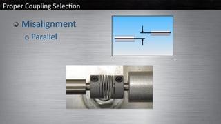
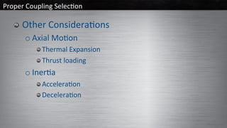
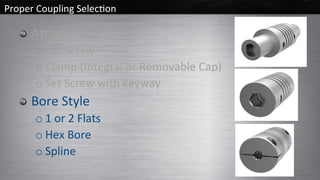
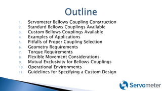
#DWwebinar
#DWwebinar
q  This webinar will be available afterwards at
www.designworldonline.com & email
q  Q&A at the end of the presentation
q  Hashtag for this webinar: #DWwebinar
Before We Start
#DWwebinar
Meet your Speakers
MODERATOR FEATURED SPEAKER
Randy Kingsbury
Vice President of Sales
and Marketing
Helical Products Company
Mike Santora
Associate Editor
Design World
FEATURED SPEAKER
Robert Collins
Technical Sales Engineer
Servometer
Proper	Coupling	Selec/on	
#1 Step
Consider the coupling an integral part of your
system during the design phase.
Not an afterthought when assembling.
__________________________
Proper	Coupling	Selec/on	
#1 Step
Consider the coupling an integral part of your
system during the design phase.
Not an afterthought when assembling.
__________________________
There are many types of couplings offering
different torque capacities, varying
misalignment capabilities, overall dimensions
(diameter & length) and materials.
Proper	Coupling	Selec/on	
#1 Step
Consider the coupling an integral part of your
system during the design phase.
Not an afterthought when assembling.
__________________________
There are many types of couplings offering different
torque capacities, varying misalignment capabilities,
overall dimensions (diameter & length) and
materials.
There is no governing body for couplings.
Proper	Coupling	Selec/on	
  General	Knowns	
o Sha6	Diameters	
o Torque	Required	
 Torque	(lbin)=(63000*HP)/RPM		
 Torque	(Nm)	=	9.5488	x	Power	(kW)	/	Speed	(RPM)		
o Torsional	Flexibility	
 deg/lbin	or	deg/Nm	
o Misalignment
Proper	Coupling	Selec/on	
  Tolerances	Stack	Up	
  Example:		Resonance	Oscillator	
					Motor,	Mount,	Base,	Bearing	Block,	
Bearings,	Sha6	
	
  Motor 	 	 					0.002	
  Motor	Mount 	 	+-	0.005		
  Base 	 	 					 	 	000	
  Bearing	Block 	 	+-	0.005	
  Bearings 	 	 				0.0005	
  Sha6	 	 						 				0.0005	
___________________________	
Maximum	total 	 						0.013
Proper	Coupling	Selec/on	
  Misalignment	
o Angular
Proper	Coupling	Selec/on	
  Misalignment	
o Parallel
Proper	Coupling	Selec/on	
  Other	Considera/ons	
o Axial	Mo/on	
 Thermal	Expansion	
 Thrust	loading
Proper	Coupling	Selec/on	
  Other	Considera/ons	
o Axial	Mo/on	
 Thermal	Expansion	
 Thrust	loading	
o Iner/a	
 Accelera/on	
 Decelera/on
Proper	Coupling	Selec/on	
  Other	Considera/ons	
o Iner/a	
 Accelera/on	
 Decelera/on
Proper	Coupling	Selec/on	
  Other	Considera/ons	
o  Axial	Mo/on	
  Thermal	Expansion	
  Thrust	loading	
o  Iner/al	loading	
  Accelera/on	
  Decelera/on	
o  Environmental	
  Temperature	
  Chemical	
  Medical	
o  Speed/RPM
Proper	Coupling	Selec/on	
  Abachment	
o Set	Screw	
o Set	Screw	with	keyway	
o Clamp	(Integral	or	Removable	Cap)
Proper	Coupling	Selec/on	
  Abachment	
o Set	Screw	
o Clamp	(Integral	or	Removable	Cap)	
o Set	Screw	with	keyway	
  Bore	Style	
o 1	or	2	Flats	
o Hex	Bore	
o Spline
Proper	Coupling	Selec/on	
  Price	$$$	
o A	coupling	can	be	too	big	(excessive	iner/a).
Proper	Coupling	Selec/on	
  Custom	Solu/ons	
o Quan//es	>25	
o Can	be	less	
expensive	than	
Standard	
Couplings
Proper	Coupling	Selec/on	
  Custom	Couplings
Proper	Coupling	Selec/on
Proper	Coupling	Selec/on	
  Thank	you	
o Heli-Cal.com	&	MachinedSprings.com
Stock & Custom Engineered Bellows Couplings
1.  Servometer Bellows Coupling Construction
2.  Standard Bellows Couplings Available
3.  Custom Bellows Couplings Available
4.  Examples of Applications
5.  Pitfalls of Proper Coupling Selection
6.  Geometry Requirements
7.  Torque Requirements
8.  Flexible Movement Considerations
9.  Mutual Exclusivity for Bellows Couplings
10.  Operational Environments
11.  Guidelines for Specifying a Custom Design
Bellows couplings are an assembly 

of two end pieces and a thin walled 

metal bellows. The thin walled Metal
Bellows are made by electroplating
Nickel metal onto a precision-machined
mandrel and then chemically removing
the mandrel so that all that remains
is the electroformed bellows.
Servometer produces parts using our 

signature Nickel-Cobalt Alloy, FlexNickel®

It can be used with other surface finishes

including copper, gold, and silver or a 

combination depending upon media compatibility and conductivity.
   Diameters from ¼” to 2.4”
   Lengths from 0.48” to 2.4”
   Torque range from 2 in-oz up to 4,000 in-oz
   Temperature Range from -58° F up to 260° F
   Zero Backlash
   Low Windup/High Torsional Stiffness
   100,000,000 Cycle Life Rating within rating limits
(Compression, Bending, and Offset are MUTUALLY
EXCLUSIVE)
}  Form, Fit and Function Optimized for Your
Application
◦  Bore sizes
◦  Unique ends or flanges
◦  Unique Performance Values
◦  Increased Torque
◦  Operating Temp up to 300°F
}  It’s all about geometry.
}  Torque requirements will match bore
size.
}  My last bellows coupling broke so I need
either higher torque or a different
design.
◦  Cycle life -100,000,000 cycles determined by:
–  1 rotation = 2 cycles
–  Amount of Compression, Offset, Bending
–  NO EXCURSIONS
}  Operational environment is not
important.
}  Speed of rotation is not important.
}  I don’t have enough time for a
custom design.
}  Design Envelope Restricts Selection
◦  Outside Diameter
–  Custom solutions with thicker walls might
meet higher torque requirements with
smaller diameters.
◦  Overall Length
–  Bellows Couplings are “Hollow”
–  Larger diameter may be necessary.
–  Set-Screw Bellows Couplings are shorter
than clamping style.
}  Torque of Motor is NOT
the Maximum Torque.
◦  Gearboxes provide a multiplier to the
available torque at the input shaft = to the
speed ratio.
◦  Starting Torque of Motor can be 3X – 5X of
standard operating Torque.
◦  When a Bellows Coupling is used in
compression only 75% of allowable
coupling Torque rating should be
considered Maximum Allowable
◦  Pulleys and Moments of Inertia must be
considered to calculate maximum
instantaneous torque.
}  Compression, Offset, Bending are 

Mutually Exclusive.
◦  % of above properties with respect to 

maximum allowed when added must 

not exceed 100%
◦  Bellows Couplings are quite flexible 

but should not be abused.
}  More Compression/Offset/Bending 

Required
◦  Coupling can be de-rated 

(less than 100,000,000 cycles) to 

achieve a more flexibility for 

reduced life.
}  Compression on Bellows Coupling
◦  Use 75% of Maximum Torque
Allowed.
Product
Specs
Parallel
Offset
Bending Compression Allowable
Torque
Comments
FC-1@
1 X 10⁸
Cycles
0.076” 31° 0.107” 2 in-oz Allowable
Example 1 0
(0%)
31°
(100%)
0
(0%)
2 in-oz All Angular
Full Torque
Example 2 0
(0%)
15.5 (50%) 0.05
(50%)
1.5 in-oz 50/50 Mix
75% of rated
Torque
FC-1 @
1 X 10⁴
cycles
0.144” 58.9° .203” 2 in-oz Increased
Movement for
10,000 cycles
}  Temperature
◦  Max operating temp for Servometer bellows
couplings is 260°F
◦  Min Operating Temp for Servometer Bellows has
not yet been determined.
}  Corrosion Resistance
◦  Servometer Bellows Couplings are an assembly
–  Material: Servometer FlexNickel
–  303 Stainless Steel Hubs (Aluminum also available)
◦  Servometer Bellows Couplings typically suitable
for high PH environments.
}  Collect ALL pertinent information
◦  Temperature of Operation
◦  Corrosion Potentials (Materials of Construction)
◦  Type of Movement (How much of each?)
–  Offset (even small amounts can count)
–  Compression
–  Bending
◦  Max Torque
◦  Speed of Rotation
}  Standard or Custom
}  Know your Geometry
}  Torque Requirements
}  Flexibility Requirements
}  Operational Environment
}  Guidelines for Custom Parts
Cedar Grove, NJ,
973.785.4630
servometer.com
http://buy.servometer.com
#DWwebinar
Questions?
MODERATOR FEATURED SPEAKER
Randy Kingsbury
Vice President of Sales
and Marketing
Helical Products Company
RKingsbury@hel-cal.com
Mike Santora
Associate Editor
Design World
msantora@wtwhmedia.com
FEATURED SPEAKER
Robert Collins
Technical Sales Engineer
Servometer
RobertC@servometer.com
#DWwebinar
q  This webinar will be available at
designworldonline.com & email
q  Tweet with hashtag #DWwebinar
q  Connect with Design World
q  Discuss this on EngineeringExchange.com
Don’t Forget!
#DWwebinar

Proper coupling selection: what you’re probably missing