RAMAKRISHNA MISSION SHILPAMANDIRA
TOPIC- 3 PHASE TRANSFORMER, CONSTRUCTION AND APPLICATIONS
CHANDAN MAITRA
ELECTRICAL ENGINEERING DEPARTMENT
ROLL NO 19
2ND
YEAR 3RD
SEMESTER
 Transformer is a static bilateral electrical device.
 It transfers electrical energy from one circuit to another circuit without changing its
frequency.
 Used to increase or decrease voltage or current.
 It works only AC power supply.
 Transformers rated in KVA.
 Efficiency of a transformer is nearly about 95-99%
 It is electrically separate magnetically coupled.
INTRODUCTION
PARTS OF 3 PHASE TRANSFORMER
1.CORE
2.WINDING
3.INSULATION
4.TRANSFORMER TANK
5.TRANSFORMER OIL
6.BUCHHOLZ RELAY
7.CONSERVATOR TANK
8.BREATHER
9.EXPLOSION VENT
10.BUSHING
11.RADIATOR
CONSTRUCTION OF A THREE PASE TRANSFORMER
High voltage
bushing
WORKING PRINCIPLE OF THREE PHASE TRANSFORMER
• It works on FARADAY’S principle of mutual
induction.
• When AC supply is given to the primary winding
an alternating flux induced in the core.
• EMF is induced in the secondary winding for the
alternating flux .
• Current of transformer follows FLAMING’S right
hand rule.
EQUATION OF A TRANSFORMER
1.Induced EMF of a transformer,E=4.44ՓmfN
where,
E=RMS value of the induced emf
Փm = maximum value of flux
f=frequency of the supply
N=number of turns of the coil
2.Efficiency of a transformer(ɳ)=(output power/input power) x 100
Transformers for 3 phase circuits can be constructed by in one of the following ways:
1.Three separate single phase transformers are suitably connected for 3 phase operation.
such an arrangement is called a 3 phase bank transformers.
2.A single 3 phase transformer in which the cores and windings for all three phases are
combined in a single structure.
According to core construction 3 phase transformer can be divided into two types:
A 3 phase transformer consists of three transformers,either separate or combined on one
core. The primaries and secondaries of any 3 phase transformer can be independently
connected in either a star(Y) or delta( ).
Windings of athree phase transformer can be connected in various configurations as
1.star-star.
2.star-delta.
3.delta-star.
4.delta-delta.
5.open delta.
Three phase transformer winding connections
APPLICATIONS
MANUFRACTURERS
CONCLUSION
• Transformer is a static bilateral device that transfers electrical energy from one circuit to another circuit
without changing it’s frequency.
• Main part of the transformer are core, winding and insulation.
• It works only in AC
• Transformer oil acts as well as coolant and insulator.
• Efficiency of a transformer is nearly 95-99%.
• Three phase transformer is used to transfer large amount of power transfer.
• Used in power stations,industries,substations,railways etc.
• As per connection 3 phase transformers are STAR-STAR,STAR-DELTA,DELTA-STAR,DELTA-DELTA, OPEN DELTA.
THANK YOU

3 phase transformer construction and working

  • 1.
    RAMAKRISHNA MISSION SHILPAMANDIRA TOPIC-3 PHASE TRANSFORMER, CONSTRUCTION AND APPLICATIONS CHANDAN MAITRA ELECTRICAL ENGINEERING DEPARTMENT ROLL NO 19 2ND YEAR 3RD SEMESTER
  • 2.
     Transformer isa static bilateral electrical device.  It transfers electrical energy from one circuit to another circuit without changing its frequency.  Used to increase or decrease voltage or current.  It works only AC power supply.  Transformers rated in KVA.  Efficiency of a transformer is nearly about 95-99%  It is electrically separate magnetically coupled. INTRODUCTION
  • 3.
    PARTS OF 3PHASE TRANSFORMER 1.CORE 2.WINDING 3.INSULATION 4.TRANSFORMER TANK 5.TRANSFORMER OIL 6.BUCHHOLZ RELAY 7.CONSERVATOR TANK 8.BREATHER 9.EXPLOSION VENT 10.BUSHING 11.RADIATOR
  • 4.
    CONSTRUCTION OF ATHREE PASE TRANSFORMER High voltage bushing
  • 5.
    WORKING PRINCIPLE OFTHREE PHASE TRANSFORMER • It works on FARADAY’S principle of mutual induction. • When AC supply is given to the primary winding an alternating flux induced in the core. • EMF is induced in the secondary winding for the alternating flux . • Current of transformer follows FLAMING’S right hand rule.
  • 6.
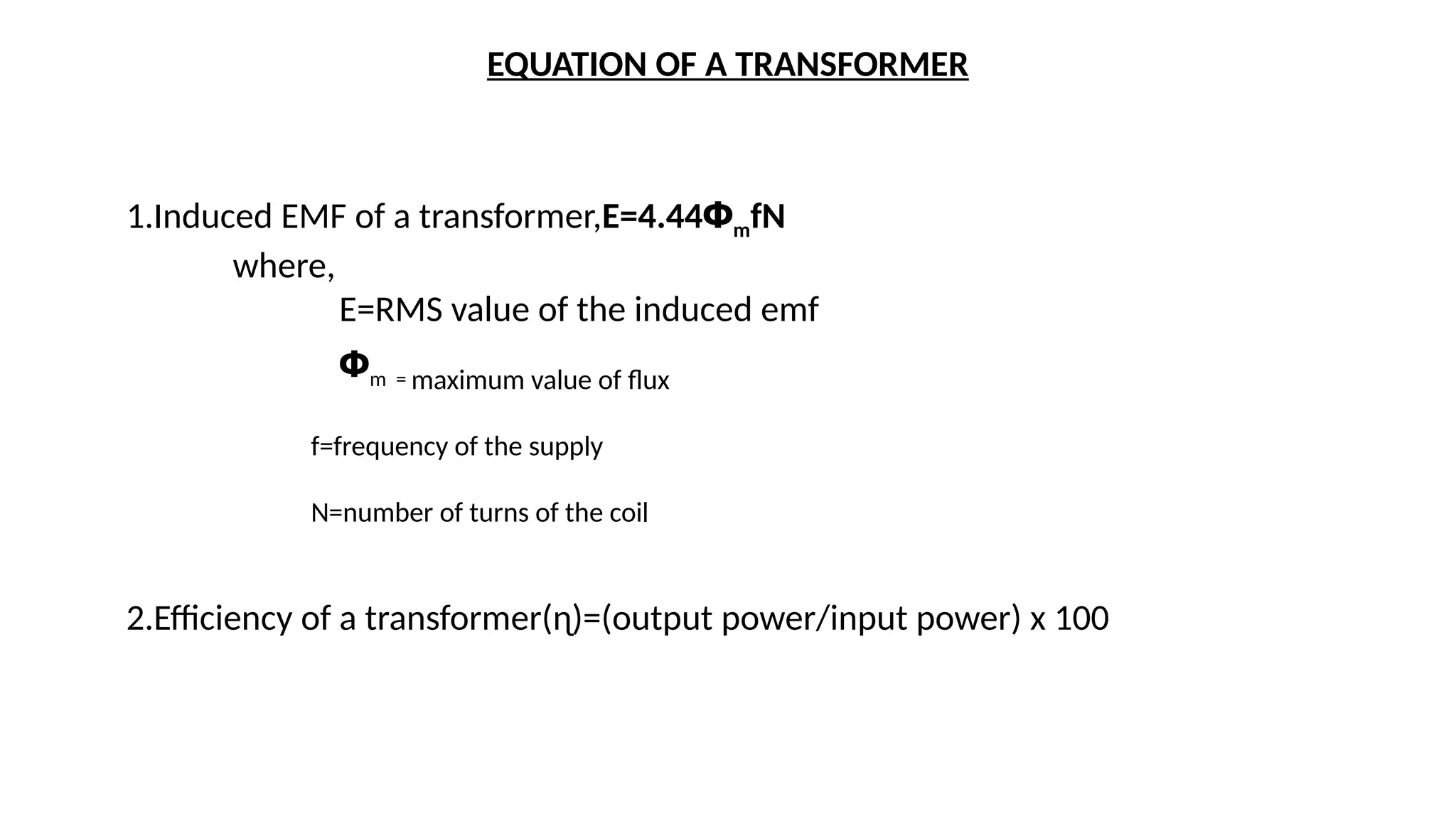
    EQUATION OF ATRANSFORMER 1.Induced EMF of a transformer,E=4.44ՓmfN where, E=RMS value of the induced emf Փm = maximum value of flux f=frequency of the supply N=number of turns of the coil 2.Efficiency of a transformer(ɳ)=(output power/input power) x 100
  • 7.
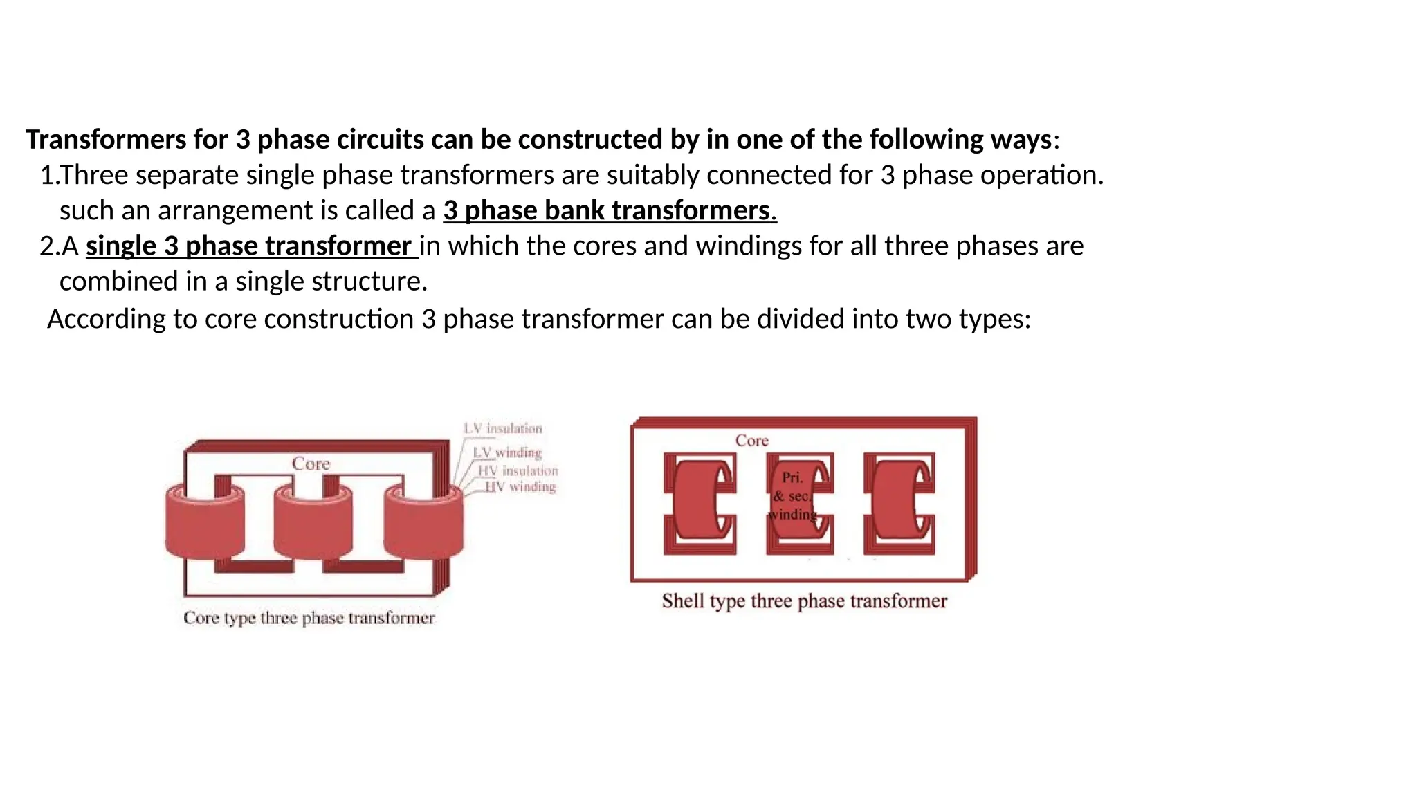
    Transformers for 3phase circuits can be constructed by in one of the following ways: 1.Three separate single phase transformers are suitably connected for 3 phase operation. such an arrangement is called a 3 phase bank transformers. 2.A single 3 phase transformer in which the cores and windings for all three phases are combined in a single structure. According to core construction 3 phase transformer can be divided into two types:
  • 8.
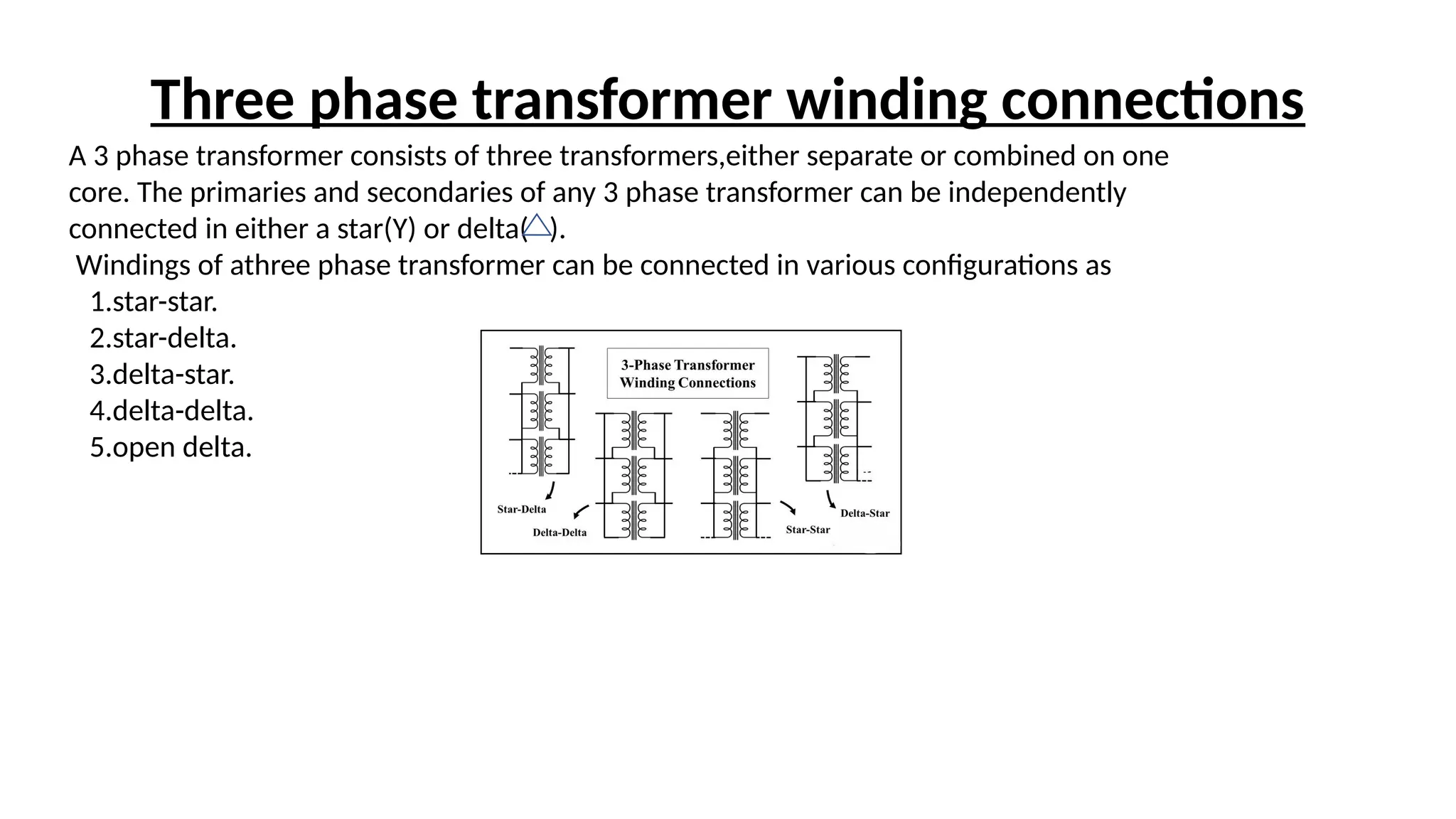
    A 3 phasetransformer consists of three transformers,either separate or combined on one core. The primaries and secondaries of any 3 phase transformer can be independently connected in either a star(Y) or delta( ). Windings of athree phase transformer can be connected in various configurations as 1.star-star. 2.star-delta. 3.delta-star. 4.delta-delta. 5.open delta. Three phase transformer winding connections
  • 9.
  • 10.
  • 11.
    CONCLUSION • Transformer isa static bilateral device that transfers electrical energy from one circuit to another circuit without changing it’s frequency. • Main part of the transformer are core, winding and insulation. • It works only in AC • Transformer oil acts as well as coolant and insulator. • Efficiency of a transformer is nearly 95-99%. • Three phase transformer is used to transfer large amount of power transfer. • Used in power stations,industries,substations,railways etc. • As per connection 3 phase transformers are STAR-STAR,STAR-DELTA,DELTA-STAR,DELTA-DELTA, OPEN DELTA.
  • 12.