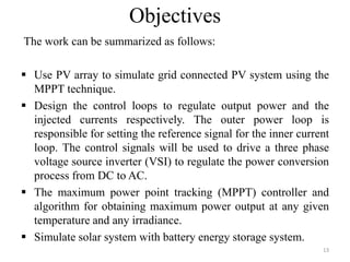
The document presents a project on developing a MATLAB/Simulink model of a grid-connected solar PV system to address the growing energy crisis and reliance on fossil fuels, especially in the context of India's solar potential. It covers the project's objectives, literature review, system design, software implementation, and simulation results, demonstrating the effectiveness of the Maximum Power Point Tracking (MPPT) algorithm for optimizing energy output. The presentation concludes with future work aimed at enhancing MPPT algorithms and exploring new control strategies for solar and hybrid energy systems.


![LITERATURE REVIEW
From the existing literature survey, it shows that only 30-
40% of energy incident on PV array is converts into
electrical energy. For enhance maximum power from panel
the algorithm is needed is Maximum Power Point Tracking
algorithm.
Major literature survey has been done for the Solar PV
system. Review of some papers is described below which
are used in reference of this work:
Sachin Jain and Vivek Agarwal, et al. [1] presents a highly
efficient inverter for PV systems which are linked with the
grid. The presented inverter configuration boosts the low
7](https://image.slidesharecdn.com/presentation1212-240617075250-4e541e42/85/THREE-PHASE-GRID-CONNECTED-SOLAR-PV-SYSTEM-7-320.jpg)
![8
voltage across PV array. It convert the generate dc power into ac
power to supply power to utility. The presented configuration has
several advantageous such as compact size, low cost etc. The
array acts as a source to the grid. The design process and terms is
incorporated through steady state analysis.
Trishan Esram, et al. [2] discussed different techniques for
extracting maximum power from photovoltaic arrays. There are
at least 19 different methods discussed in this paper, with many
different conditions and compare different characteristics. The
issue is study by all MPPT is to achieve the voltage or current it
should operate to generate the maximum output power under
variable atmospheric conditions.
Contd.](https://image.slidesharecdn.com/presentation1212-240617075250-4e541e42/85/THREE-PHASE-GRID-CONNECTED-SOLAR-PV-SYSTEM-8-320.jpg)
![ Hiren Patel and Vivek Agarwal, et al. [3] studies the
performance of photovoltaic arrays under partially shaded
conditions. PV array characteristics are study. Most of the
available methods are not able to extract maximum power
when there is cloudy weather or under variable irradiation. The
authors presented a new algorithm to track the power under
such conditions.
Bhim singh et al. [4] discussed the analysis and control aspects
of standalone solar PV system for low power applications. The
battery is used as energy storage system which is charged and
stores it. The stored energy is feed to the load using inverter by
converted into AC of 220 V, 50Hz.
9
Contd.](https://image.slidesharecdn.com/presentation1212-240617075250-4e541e42/85/THREE-PHASE-GRID-CONNECTED-SOLAR-PV-SYSTEM-9-320.jpg)
![ Hao Qian et al. [5] proposes a high-efficiency battery based
energy storage system. The used energy storage system has a
bidirectional ac–dc converter. For applying active charge
equalization of the battery, energy management system
estimating the SOC and health condition of each cell.
Prototypes have been designed and implement to validate the
performance.
Hamid R. Teymour et al. [6] presents the theoretical
framework of the proposed modulation technique. A new
control algorithm is also presented in order to control the
power delivery between the system and grid. This
simultaneously provides maximum power point tracking
(MPPT) operation for the solar PV.
10
Contd.](https://image.slidesharecdn.com/presentation1212-240617075250-4e541e42/85/THREE-PHASE-GRID-CONNECTED-SOLAR-PV-SYSTEM-10-320.jpg)
![ Jung-Ming Kwon et al. [7] study a PV system along with
maximum power point tracking techniques. MPPT using a
power hysteresis tracks the MPP. Also a proportional and
integral controller is recommended to control the dc link
voltage faster.
Yongsoon Park et al. [8] describe a grid synchronization
technique. This method is essential for grid connected power
converters. PLL has been widely used as a realization scheme,
but additional efforts are still required to deal with distorted
grid voltages. The results have shown that the proposed
method carried out a better phase tracking performance for
grid synchronization.
11
Contd.](https://image.slidesharecdn.com/presentation1212-240617075250-4e541e42/85/THREE-PHASE-GRID-CONNECTED-SOLAR-PV-SYSTEM-11-320.jpg)
![Contd.
Michael E. Ropp, et al. [9] focus on modeling of grid connected
PV system in MATLAB environment. Simulation results show
the behavior of PV would be of high value. On the other hand,
most of today’s models don’t precisely model, to study the
dynamics behavior of the maximum power point trackers
(MPPTs). The simulation results are compared with real time
results of the system.
Guishi Wang et al. [10] proposes a power smoothing strategy for
1 MW grid connected solar PV power plant. A HESS composed
of battery and a super capacitor bank is used, to smooth the
unpredictable output power of the PV plant. The PV plant with
the HESS has been modeled using MATLAB/simulink and
PLECS software environment. 12](https://image.slidesharecdn.com/presentation1212-240617075250-4e541e42/85/THREE-PHASE-GRID-CONNECTED-SOLAR-PV-SYSTEM-12-320.jpg)
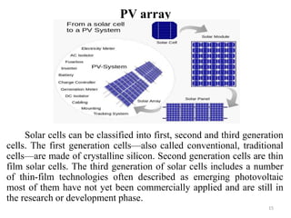


![Incremental Conductance Based MPPT
19
The incremental conductance (IncCond) method is based on
the fact that the slope of the PV array power voltage curve is zero at
the MPP, positive on the left of the MPP, and negative on the right, as
given by, [9]
•dP/dV = 0, at MPP
•dP/dV > 0, left of MPP
•dP/dV < 0, right of MPP
Since
•ΔI/ΔV = −I/V, at MPP
•ΔI/ΔV > − I/V, left of MPP
•ΔI/ΔV < − I/V, right of MPP
V
I
V
I
dV
dI
V
I
dV
IV
d
dV
dP
)
(
᷉
P-V Characteristics for Incremental Conductance method](https://image.slidesharecdn.com/presentation1212-240617075250-4e541e42/85/THREE-PHASE-GRID-CONNECTED-SOLAR-PV-SYSTEM-19-320.jpg)
![20
Flowchart of Incremental Conductance[9]](https://image.slidesharecdn.com/presentation1212-240617075250-4e541e42/85/THREE-PHASE-GRID-CONNECTED-SOLAR-PV-SYSTEM-20-320.jpg)


![References
33
[1] Best practice guide-Photovoltaics PV
[2] Masters, Gilbert M., Renewable and efficient electric power systems. John Wiley & Sons, 2004
[3] http://en.wikipedia.org/wiki/Photovoltaic_system
[4] G.D.Rai, non-convenetinal energy sources, khanna publications.
[5] Sachin Jain and Vivek Agarwal, “A Single-Stage Grid Connected Inverter Topology for Solar PV Systems with
Maximum Power Point Tracking”, IEEE Trans. Power Electronics, vol. 22, no. 5, pp.1928-1940, September 2007
[6]Trishan Esram, “Comparison of Photovoltaic Array Maximum Power Point Tracking Techniques”, IEEE
TRANSACTIONS ON ENERGY CONVERSION, VOL. 22, NO. 2, PP. 439-449, JUNE 2007.
[7]Michael E. Roop, “Devlopment of a MATLAB simulink model of a single phase grid connected PV
system,”IEEE Trans. Energy Conversion, 2009.
[8] Sangita R Nandurkar ,”Design and simulation of three phase inverter for grid connected PV systems”,Third
biannual national conference, NCNTE-2012 FEB 24-25.
[9] Wang , “A novel single stage full bridge buck boost inverter” IEEE Trans. On Power Electronics, vol. 19, no 1,
jan 2014.
[10] Patel ,H. , “Maximum power point tracking scheme for PV systems operating under partially shaded
conditions”, IEEE Transon industrial Electronics vol 55april 2008.](https://image.slidesharecdn.com/presentation1212-240617075250-4e541e42/85/THREE-PHASE-GRID-CONNECTED-SOLAR-PV-SYSTEM-33-320.jpg)
![[11] Bhim Singh, Design and control of small power standalone solar PV energy system”, Asian Power Electronics journal, oct
2012.
[12] Ramprabha R ,”Design and modeling of standalone solar PV charging system,” Int journal of computer applications vol 18
no 2, march 2011.
[13] Hao Qian A High-Efficiency Grid-Tie Battery Energy Storage System IEEE TRANSACTIONS ON POWER ELECTRONICS, VOL. 26,
NO. 3, MARCH 2011
[14] Hamid R, “Solar PV and battery storage integration using a new configuration of a three level NPC inverter with advanced
control strategy”, IEEE Trans on energy conversion, vol 29,no 2, june 2014.
[15]Sarina Adhikari, “Coordinated V-f and P-Q Control of Solar Photovoltaic Generators With MPPT and Battery Storage in
Microgrids”, IEEE TRANSACTIONS ON SMART GRID, VOL. 5, NO. 3, MAY 2014 pp 1270-1282.
[16] Huang-Jen Chiu,“Design and Implementation of a Photovoltaic High-Intensity-Discharge Street Lighting System, IEEE
TRANSACTIONS ON POWER ELECTRONICS, VOL. 26, NO. 12, DECEMBER 2011
[17]Jung-Min Kwon, “Three-Phase Photovoltaic System With Three-Level Boosting MPPT Control”, IEEE TRANSACTIONS ON
POWER ELECTRONICS, VOL. 23, NO. 5, SEPTEMBER 2008 pp 2319-2328.
[18]Yongsoon Park, Phase-Locked Loop Based on an Observer for Grid Synchronization”, Phase-Locked Loop Based on an
Observer for Grid Synchronization, IEEE TRANSACTIONS ON INDUSTRY APPLICATIONS, VOL. 50, NO. 2, MARCH/APRIL 2014
pp1256-1266.
[19]Guishi Wang, Power Smoothing of Large Solar PV Plant Using Hybrid Energy Storage”, IEEE TRANSACTIONS ON SUSTAINABLE
ENERGY, VOL. 5, NO. 3, JULY 2014 pp 834- 843.
[20]Boddu Veeraiah, “Co-ordinated control of renewable energy resources for grid connected and autonomous microgrid
modes”, M.Tech Thesis, May 2012, IIT-Delhi
[21]Frede Blaabjerg, “Overview of Control and Grid Synchronization for Distributed Power Generation Systems”, IEEE
TRANSACTIONS ON INDUSTRIAL ELECTRONICS, VOL. 53, NO. 5, OCTOBER 2006 ,pp1398-1410.
[22] http://www.mathworks.in
34](https://image.slidesharecdn.com/presentation1212-240617075250-4e541e42/85/THREE-PHASE-GRID-CONNECTED-SOLAR-PV-SYSTEM-34-320.jpg)