Downloaded 10 times


![What Is Pivot Algorithm?
• The Pivot algorithm is a very efficient ‘dynamic’ algorithm for
generating d-dimensional canonical ensemble.[1][2][3]
• It drastically modifies the chain dimension.](https://image.slidesharecdn.com/szqo4whdtv664j3mxmik-signature-3635e86c410057faf8ec91d159b5bbc6353ff889a1ddd01200b2aa2175548e81-poli-150501080108-conversion-gate01/85/Pivot-Algorithm-2-320.jpg)

![References
• [1] M. Kroger, Introduction to Computational Physics,
Lecture Notes; ETH Zurich (2008).
• [2] Joachim P. Wittmer et. al., Monte Carlo Simulation of
Polymers, NIC Series 23, 83-140 (2001).
• [3] Nathan Clisby, Efficient Implementation of pivot
algorithm for self-avoiding walks, ARC, (2010).](https://image.slidesharecdn.com/szqo4whdtv664j3mxmik-signature-3635e86c410057faf8ec91d159b5bbc6353ff889a1ddd01200b2aa2175548e81-poli-150501080108-conversion-gate01/85/Pivot-Algorithm-9-320.jpg)

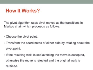
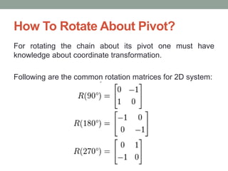
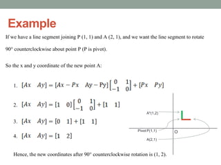
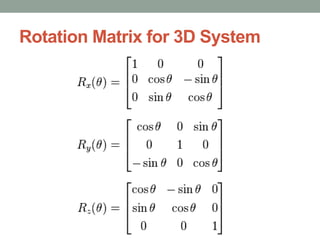
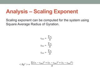
The pivot algorithm is a dynamic method for generating d-dimensional canonical ensembles by modifying chain dimensions through pivot moves in a Markov chain. It involves selecting a pivot point and rotating coordinates while checking for self-avoiding walks to determine accepted moves. Analysis includes calculating the scaling exponent through the square average radius of gyration for different dimensions.