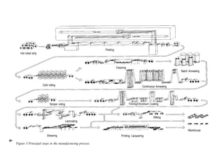
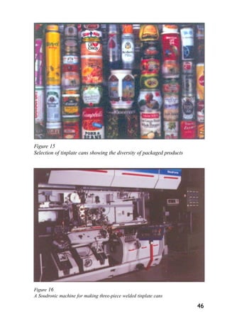
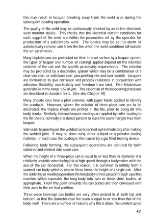
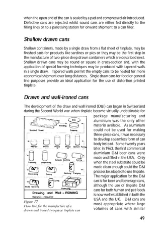
Downloaded 852 times


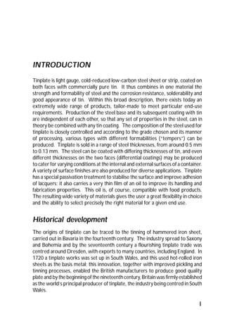


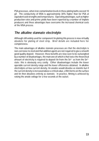

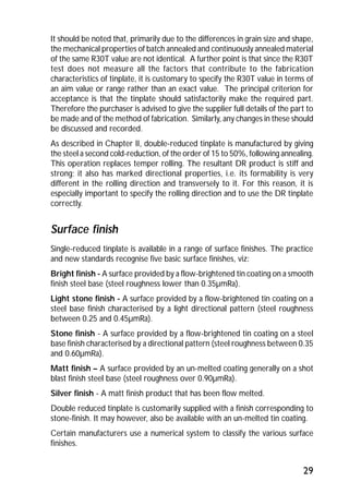
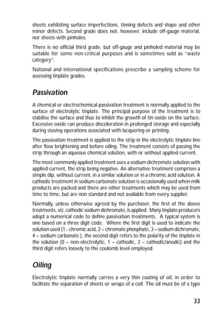
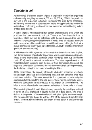
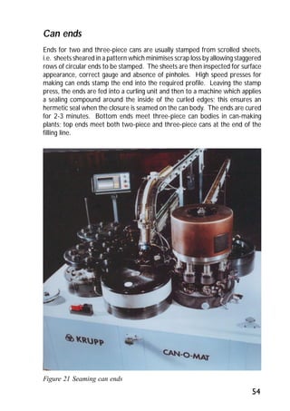
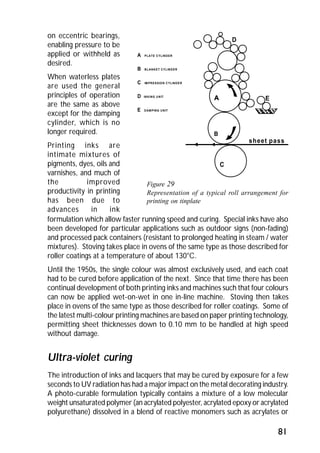
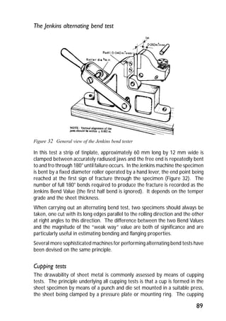
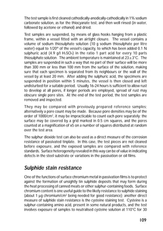
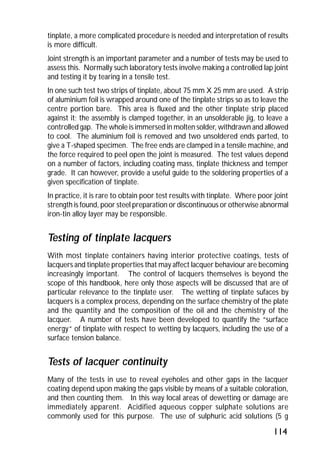
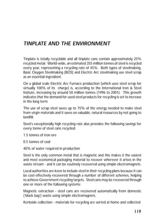
![Ecology easy-open ends [“Stay-on-tab”] are widely made in aluminium for
beverage cans. For such ends, the limits of the aperture are scored in the metal
and a tab is riveted in place so that on lifting the tab, the aperture is ruptured
inwards allowing access to the contents. The tab and aperture remain attached
to the end. Different aperture shapes are available, the most common being
oval. Increasingly, a “Gulper” or large opening end [LOE] is being used as this
allows the product to be dispensed more rapidly from the can. Manufacturing
speeds continue to rise substantially with multi-die shell and conversion presses
predominating.
A number of beverage tinplate easy-open ends have been developed though
not widely commercialised; with a harder, springy material like steel, the scoring
operation is even more critical since the scoring must be deep enough to
permit detachment by pulling, yet not so severe as to introduce a risk of leakage.
Furthermore, there must be no damage to fingers from sharp edges. One
design developed in Australia has a press-button can end for beer and soft
drinks cans. There are two circular press tabs of different sizes. These tabs are
integrally hinged to the end and cannot be detached, thus they neither fall into
the can contents nor add to litter problems. The end is opened by first depressing
the smaller tab to release gas pressure and then depressing the larger tab to
allow the contents to be poured. In a modification the smaller tab is situated
55
Figure 22 Easy-open can end](https://image.slidesharecdn.com/guidetotinplate-141016055036-conversion-gate01/85/Guide-to-tinplate-58-320.jpg)
![inside the larger opening; this obviates the risk of contents spurting out when
the buttons are pressed in. These ends are manufactured by subjecting a normal
end to a series of stamping operations, using transfer presses to form the tabs
and apertures, applying a sealant around the internal cut edges to prevent
corrosion and to provide an hermetic seal and coating the external cut edges
with a repair lacquer. Tolerances for the die stages are said to be less critical
than in the case of ring-pull openings and only low press tonnages are needed.
Aluminium and tinplate full aperture easy-open ends have been developed for
both dry and processed foodstuffs. Normally, the full-aperture end is operated
by a riveted ring-pull, similar to that used for beverage containers but detaching
with the centre panel of the end. The end is scored circumferentially close to
the end seam, so that the maximum area of the end is open when the panel is
removed. Steel provides better performance for a given end thickness and is
therefore more common where the food processing produces high internal can
pressures. Harder steels have been the trend with much development around
the industry currently focused toward using double-reduced steel. This latter
material is already common for classic [non-easy open] ends. With steel in
particular, careful attention must be paid to all stages of the manufacturing process
if a high level of end consistency is to be achieved. The achievement of acceptably
low opening forces requires similar attention to product design.
Some aluminium full aperture ends have folds along one or both of the score
edges as a safety feature. These are generally manufactured by collapsing a
stepped shell profile in the conversion press during end manufacture.
Certain meat and fish packs have key opening. In the case of the meat packs,
normally in rectangular cans, a narrow strip is scored into the can wall. This is
removed from the body by inserting a tag from the strip into a metal “key” and
winding off a metal strip, thus releasing one end of the container. In the case of
shallow drawn containers for fish, one end is scored around the perimeter and
the entire end is wound off using a detachable “key”.
Closures
In addition to ends for cans, tinplate is used to make bottle closures e.g. crown
corks with characteristic corrugated rims and cork or plastic pad as sealant,
ensuring a tight hermetic seal when applied to a bottle. Sheets of tinplate
decorated with the bottle top pattern, are coated with wax and then passed to
automatic presses which produce the bottletops from a series of dies. A blanking
punch cuts out the cap and the drawing punch passes through to form the
crown. After blanking and forming, the closures are lined with composition
cork, or moulded polythene reseals, or flowed-in plastic liners.
56](https://image.slidesharecdn.com/guidetotinplate-141016055036-conversion-gate01/85/Guide-to-tinplate-59-320.jpg)


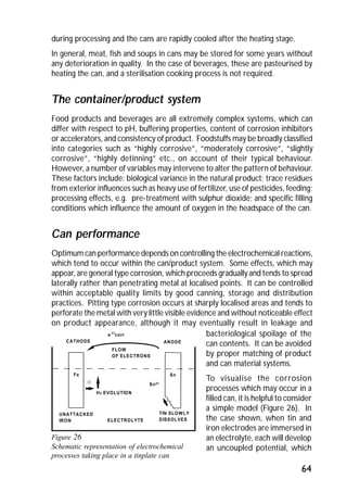
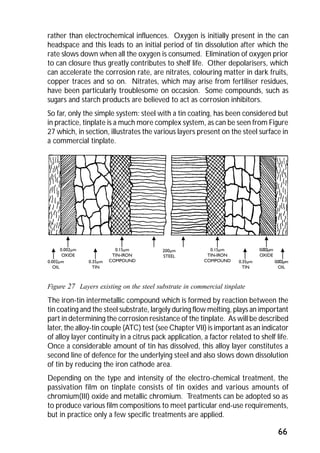


ITRI Ltd is the world's foremost authority on tin and its applications. They conduct research to expand the use of tin and improve technological processes involving tin. Their research areas include tinplate packaging, tin coatings, solder technology, and chemical and environmental applications. Tinplate is produced by coating thin mild steel sheet with tin. The steel sheet is made through a process involving basic oxygen steelmaking and continuous casting into slabs. The slabs then undergo rolling, annealing, pickling, and coating with tin through either hot dipping or electrolysis to produce the final tinplate.