This document provides a quick reference guide for the Universal Verification Methodology (UVM) that includes:
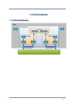
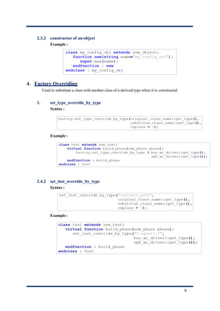
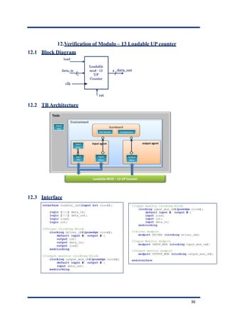
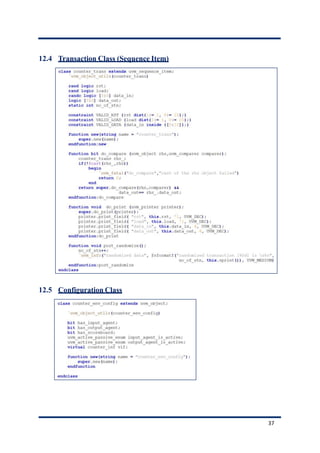
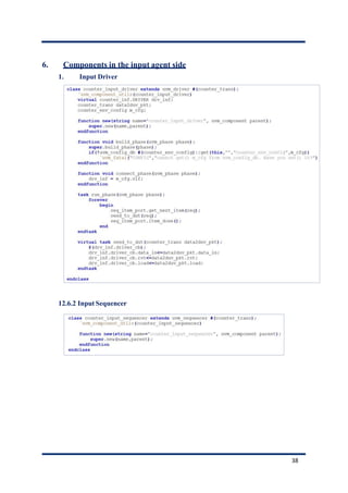
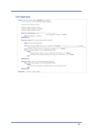
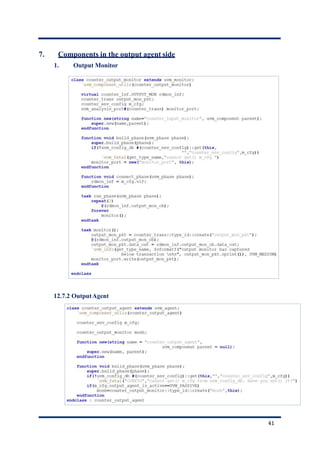
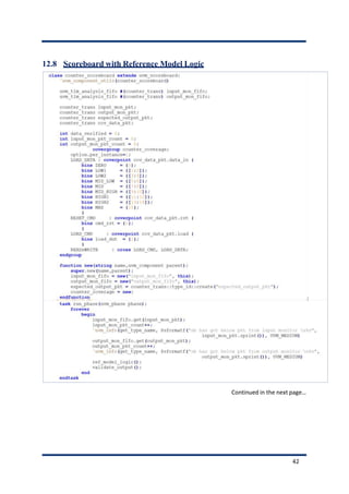
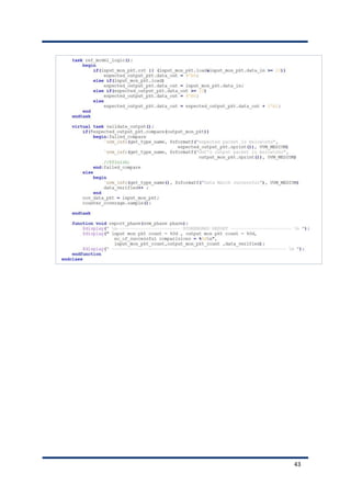
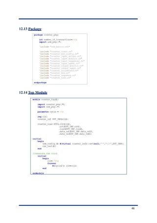
1. An overview of the UVM testbench architecture and its main components like the factory, phases, reporting, and transaction level modeling.
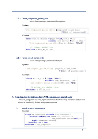
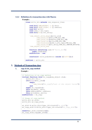
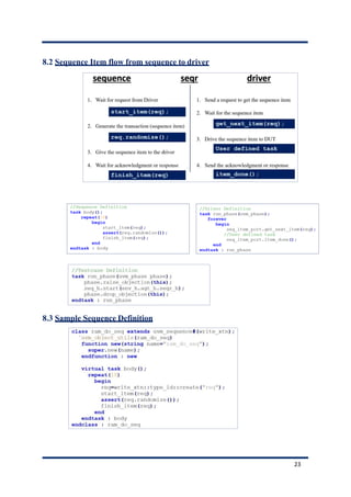
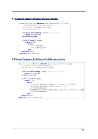
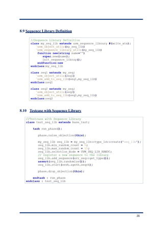
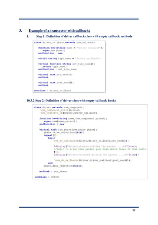
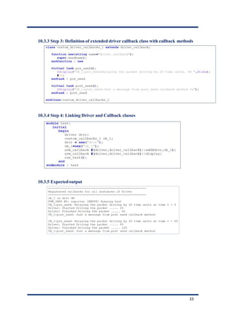
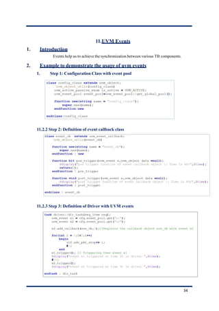
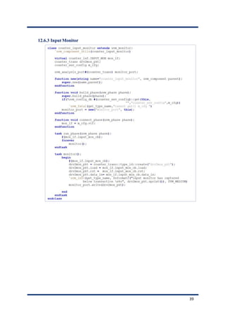
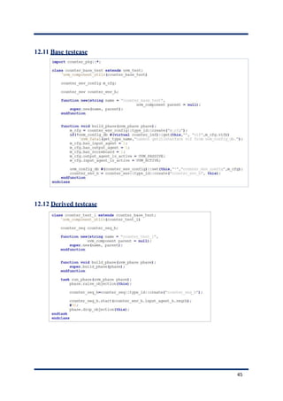
2. Instructions for defining stimulus using transactions and sequences, including registering fields, defining methods, and controlling item flow.
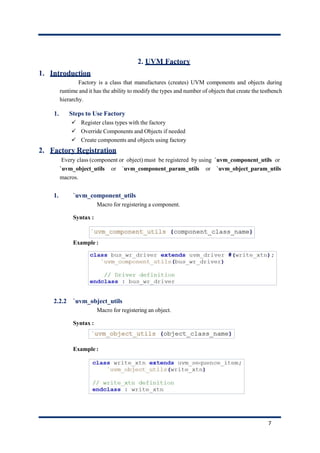
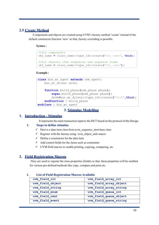
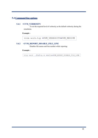
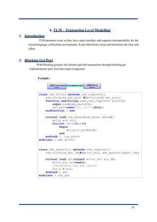
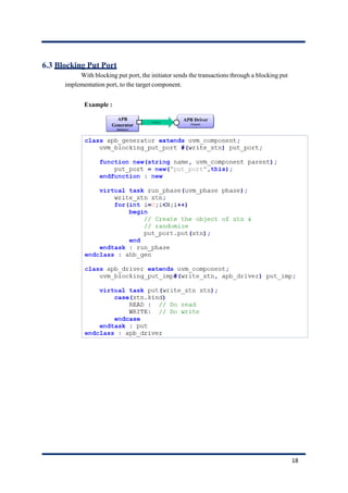
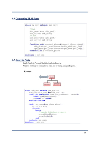
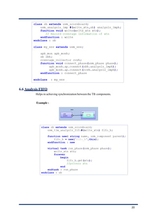
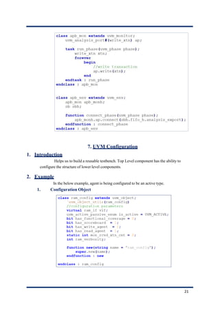
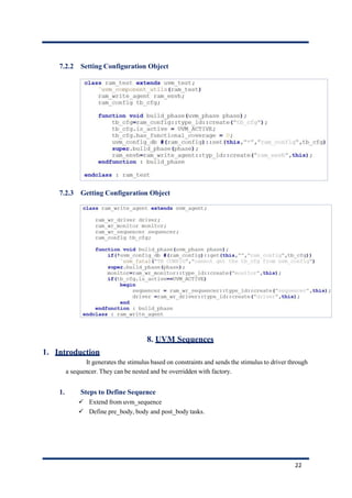
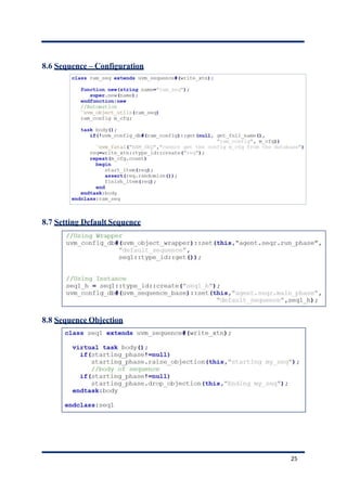
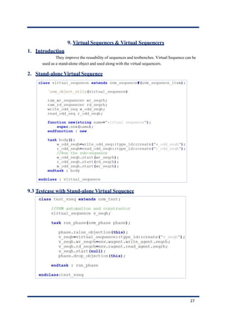
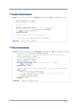
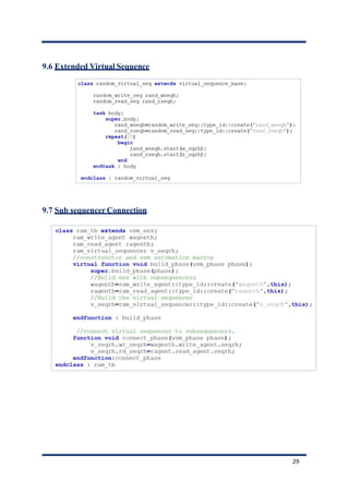
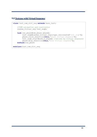
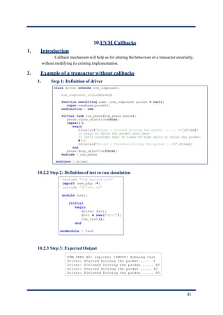
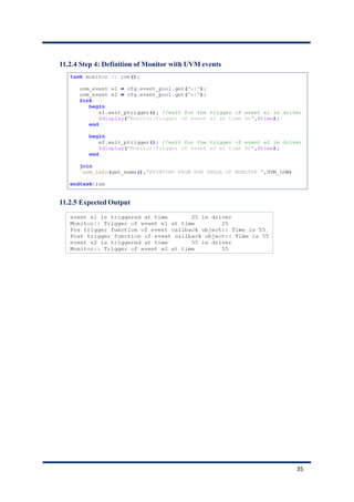
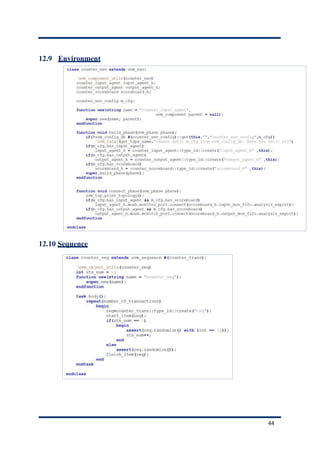
3. Details about key UVM features like the factory, phases, reporting, configuration, sequences, and virtual sequences/sequencers.