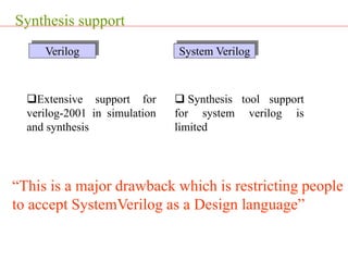
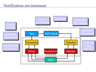
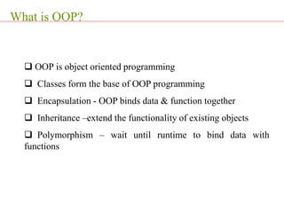
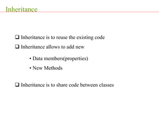
This presentation provides an introduction to SystemVerilog and its major features for verification. It defines SystemVerilog as a hardware description and verification language that is an extensive enhancement to Verilog with additional features inherited from Verilog, VHDL, C, and C++. The presentation highlights key SystemVerilog constructs for verification like queues, mailboxes, fork/join, constraints, covergroups, and interfaces. It also discusses object-oriented programming concepts in SystemVerilog like classes, inheritance and polymorphism that are useful for building reusable verification components.

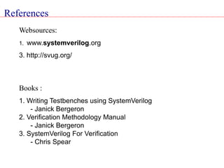
![Memory Management
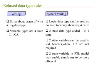
Memories in verilog are
static in nature
Example :-reg[7:0] X[0:127];
128 bytes of memory
Memories are dynamic in
nature
Allocated at runtime
Better memory management
ie,queues
Example:Logic[3:0] length[$];
an empty queue with an
unbounded size of logic data
type
Verilog System Verilog](https://image.slidesharecdn.com/systemverilogveriflcation-240319173853-5d78ea8a/85/SystemVerilog_veriflcation-and-UVM-for-IC-design-ppt-11-320.jpg)
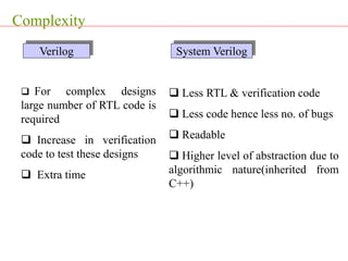
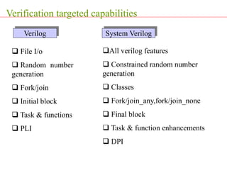
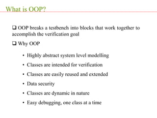

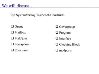
![Queue…
Data storage array [$]
• Variable size array with automatic sizing
• Searching, sorting and insertion methods](https://image.slidesharecdn.com/systemverilogveriflcation-240319173853-5d78ea8a/85/SystemVerilog_veriflcation-and-UVM-for-IC-design-ppt-50-320.jpg)
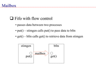
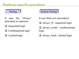
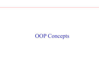
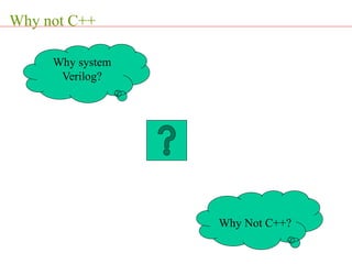
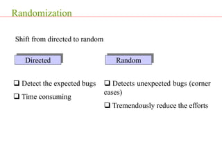
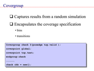
![Constraint
Control randomization
• Values for random variable can be controlled through
constraint expressions
• These are declared within constraint block
Class packet ;
rand logic [7:0] src;
rand logic [7:0] dest;
Constraint my_constraints {
src[1:0] == 2’b00; // constraint expression
…………… // always set src[1:0] to 0
}
endclass:packet](https://image.slidesharecdn.com/systemverilogveriflcation-240319173853-5d78ea8a/85/SystemVerilog_veriflcation-and-UVM-for-IC-design-ppt-57-320.jpg)
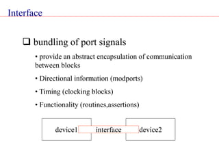
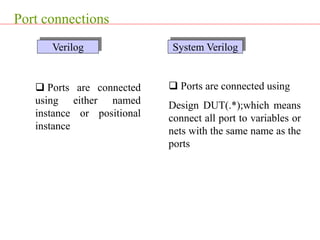
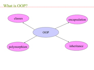
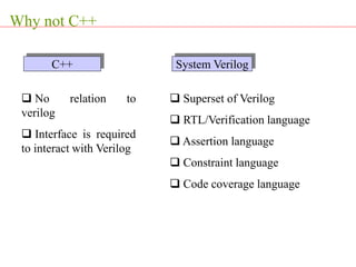
![Interface
Interface bus_a (input clock);
logic [7:0] address;
logic [31:0] data ;
bit valid ;
bit rd_wr ;
Endinterface: bus_a
Interface:An example](https://image.slidesharecdn.com/systemverilogveriflcation-240319173853-5d78ea8a/85/SystemVerilog_veriflcation-and-UVM-for-IC-design-ppt-62-320.jpg)
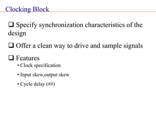
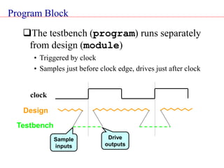
![Clocking Block
Module M1(ck, enin, din, enout, dout);
input ck,enin;
input [31:0] din ;
output enout ;
output [31:0] dout ;
clocking sd @(posedge ck);
input #2ns ein,din ;
output #3ns enout, dout;
endclocking:sd
reg [7:0] sab ;
initial begin
sab = sd.din[7:0];
end
endmodule:M1
Signals will be sampled
2ns before posedge ck
Signals will be driven
3ns after posedge ck](https://image.slidesharecdn.com/systemverilogveriflcation-240319173853-5d78ea8a/85/SystemVerilog_veriflcation-and-UVM-for-IC-design-ppt-65-320.jpg)
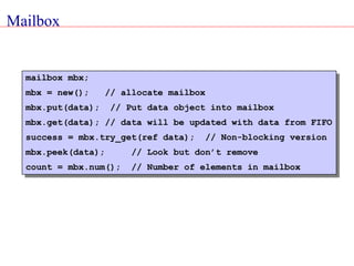
![Modports
An interface can have multiple viewpoints
• Master/Slave, Transmitter/Receiver
These can be specified using modports
Interface bus_b (input clock);
logic [7:0] addr,data;
logic [1:0] mode ;
bit ready ;
modport master (input ready,output addr,data,mode) ;
modport slave (input addr,data,mode,output ready) ;
endinterface: bus_b
All signal names
in a modport must
be declared in the
interface](https://image.slidesharecdn.com/systemverilogveriflcation-240319173853-5d78ea8a/85/SystemVerilog_veriflcation-and-UVM-for-IC-design-ppt-66-320.jpg)