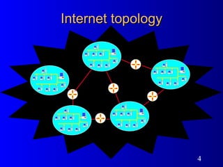
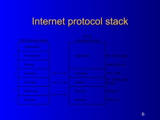
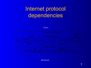
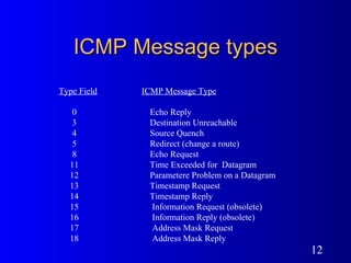
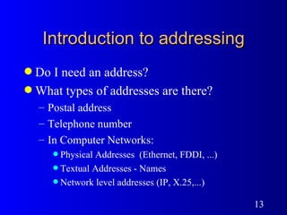
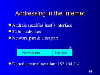
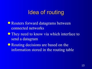
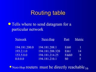
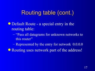
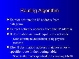
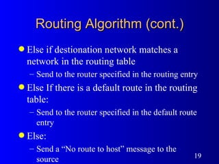
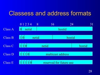
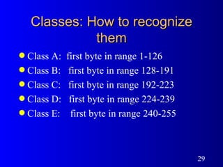
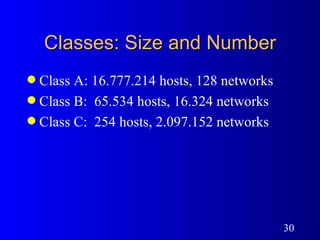
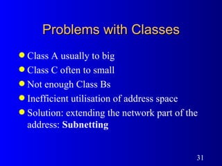
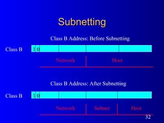
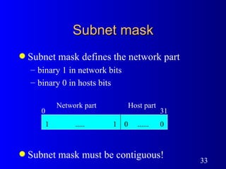
IP Addressing and Introduction to IP routing Avgust Jauk  <jauk@arnes.si> ARNES Bratislava, August 98
Agenda Internet topology Introduction to addressing Idea of routing Special  address conventions Classfull  addressing Classless addressing Routing protocols: IGPs and EGPs
Internet topology  Internet - Network of Networks Networks Based on different technology Large or small Fast or slow Variety of connected nodes Routers (Gateways) Protocols
Internet topology
Routers Packet handling Packet forwarding Routing information processing Management Miscellaneous functions
Internet protocol stack
Internet protocol dependencies Hardware Users
Layering in the Internet Application Transport Internet Network interface Application Transport Internet Network interface Internet Network interface Identical message Identical packet Identical datagram Identical datagram Identical frame Identical frame Physical  Net  1 Physical  Net  2 Gateway  G Host  A Host   B
Internet datagram format
ICMP datagram format
ICMP Message types Type Field   ICMP Message Type 0  Echo Reply 3  Destination Unreachable 4  Source Quench 5  Redirect (change a route) 8  Echo Request 11  Time Exceeded for  Datagram 12  Parametere Problem on a Datagram  13  Timestamp Request 14  Timestamp Reply 15  Information Request (obsolete) 16  Information Reply (obsolete) 17  Address Mask Request 18  Address Mask Reply
Introduction to addressing Do I need an address?  What types of addresses are there? Postal address Telephone number In Computer Networks: Physical Addresses  (Ethernet, FDDI, ...) Textual Addresses - Names  Network level addresses (IP, X.25,...)
Addressing in the Internet Address specifies host’s interface 32 bit addresses Network part & Host part Dotted decimal notation: 192.164.2.4 Network   part Host   part 0 31
Idea of routing Routers forward datagrams between connected networks They need to know via which interface to send a datagram Routing decisions are based on the information stored in the routing table
Routing table Tells where to send datagram for a particular network Network   Next-Hop   Port   Metric 194.181.200.0  194.181.208.1  Eth0  1 193.2.1.0  194.181.208.320  Eth1  14 153.5.0.0  194.181.214.25  Fddi0  8 0.0.0.0  194.181.210.1  S0  5 Next-Hop  routers   must be directly reachable
Routing table (cont.) Default Route - a special entry in the routing table: “ Pass all datagrams for unknown networks to this router” Represented by the entry for network  0.0.0.0 Routing uses network part of the address!
Routing Algorithm Extract destination IP address from datagram Extract network address from the IP address If destination network equals my network Send directly to destination using physical network Else If destination address matches a host-specific route in the routing table: Send to the router specified in the routing table
Routing Algorithm (cont.) Else if destionation network matches a network in the routing table Send to the router specified in the routing entry Else If there is a default route in the routing table: Send to the router specified in the default route entry Else: Send a “No route to host” message to the source
Populating the Routing Table Manually by network administrator:  Static Routes No dynamic changes to these routes will accur Dynamically by routing protocol Routing info is exchanged between routers The routing “metric” is used to find the best path
Static Routes Manually configured by network administrator A B
Static Routes Router cannot automatically reroute if path fails A B
Routing protocols Routers use a common protocol to exchange routing information Best path between networks or subnets is determined  by “Routing Metric” Automatic adaption to topology changes
Routing protocols 64 kbps 64 kbps 2 Mbps 2 Mbps
Special address conventions Broadcast Addresses Directed broadcast: host part all  1’s - 194.181.200.255 Limited broadcast: all 1’s -  255.255.255.255 0 means “This” host part  = 0  -  this host network part = 0  -  this network miss used as a broadcast address
Special address conventions (cont.) Loopback Address :  127.0.0.1  for testing and inter-process communication on the local machine should never appear on any network
Summary of special address conventions This host Limited broadcast (local net) Host on this net Directed broadcast for net Loopback all   0s all   0s host all   1s net 127 anything (often 1) all   1s
Classess and address formats 0 1 2 3 4 8 16 24 31 netid netid hostid hostid multicast address reserved for future use Class A Class C Class D Class E 0 0 0 0 netid hostid Class B 0 1 1 1 1 1 1 1 1 1 1
Classes: How to recognize them Class A:  first byte in range 1-126 Class B:  first byte in range 128-191 Class C:  first byte in range 192-223 Class D:  first byte in range 224-239 Class E:  first byte in range 240-255
Classes: Size and Number Class A: 16.777.214 hosts, 128 networks Class B:  65.534 hosts, 16.324 networks Class C:  254 hosts, 2.097.152 networks
Problems with Classes Class A usually to big Class C often to small Not enough Class Bs Inefficient utilisation of address space Solution: extending the network part of the address:  Subnetting
Subnetting Class B 0 1 Class B 0 1 Class B Address: Before Subnetting Class B Address: After Subnetting Network Network Host Host Subnet
Subnet mask Subnet mask defines the network part binary 1 in network bits binary 0 in hosts bits Subnet mask must be contiguous!  Network part Host part 0 31 1  .....  1 0  ......  0
Subnetting (cont.) Not limited to byte border Subnets  “0”  and  “-1” used to be reserved Subnet “0” :  this subnet Subnet “-1”:  broadcast Network administrator decides on the subnet size Network and subnet numbers used for routing decisions
Subnetting and routing  one subnet mask per particular class routing considerations  all subnets of the same class must be contiguous or static routes must be used or routing protocol must carry  also subnet  masks
Subnetting and routing all subnets of the same class must be contiguous! C 1 1 C 1 2 B C 1 4 C 1 3 C 1 C 1
Subnet mask bits 128 64 32 16 8 4 2 1 1 0 0 0 0 0 0 0 = 128 1 1 0 0 0 0 0 0 = 192 1 1 1 0 0 0 0 0 = 224 1 1 1 1 0 0 0 0 = 240 1 1 1 1 1 0 0 0 = 248 1 1 1 1 1 1 0 0 = 252 1 1 1 1 1 1 1 0 = 254 1 1 1 1 1 1 1 1 = 255
Binary Numbers =  128  + 64  +  32  +  2 128 64 32 16 8 4 2 1  Represent 226 decimal in binary: = 6 2 1 1 1 0 0 0 1 0  6 2 226 = 2 7 2 5 2 4 2 3 2 2 1 2 0 2 2 2 7 2 5 2 4 2 3 2 2 1 2 0 2 2
Subnetting a Class C split subnet mask # subnets # hosts/subnet total # hosts utilis. 1:7 128 2 252 126 99% 2:6 192 4 248 62 98% 3:5 224 8 240 30 94% 4:4 240 16 14 224 88% 5:3 248 32 6 192 76% 6:2 252 64 2 128 50% 7:1 254 / / / /
Variable Length Subnet Masks (VLSM) Subnets are of different size A means for conserving address space How to do it: how big is the biggest subnet? split the class into such pieces  split  (“sub-subnet” ) those peieces further
VLSM (cont.) How to do VLSM 0  255
VLSM and routing Prerequisites: routing protocol must carry subnet masks or  static routes must be used
Classfull Addressing: drawbacks Classfull Addressing + Subnetting at least one route per class is advertised in routing updates Number of networks is doubling faster than once per year Memory is not growing that fast Only a few routers can keep the current number of routes Route flapping
Classless addressing Introduced by CIDR - Classless InterDomain Routing Networks are grouped (aggregated) into blocks Blocks of networks are advertised New way of thinking: there are no networks numbers, but just address space prefixes there are no subnet masks, just prefix lenghts
Classless addresses notation 10.181.215.32 /27 10.181.215.32  with  mask 255.255.255.224 binary representation of mask:  11111111.11111111.11111111.11100000
Classless address notation Hosts . . . 8 16 32 64 128 256 . . . 4096 8192 16384 32768 65535 . . . Prefix . . . /29 /28 /27 /26 /25 /24 . . . /20 /19 /18 /17 /16 . . . Classful . . . 1 C . . . 16 C’s 32 C’s 64 C’s 128 C’s 1 B . . . Subnet Mask . . . 255.255.255.248 255.255.255.240 255.255.255.224 255.255.255.192 255.255.255.128 255.255.255.0 . . . 255.255.240.0 255.255.224.0 255.255.192.0 255.255.128.0 255.255.0.0 . . .
Classless network aggregation - Supernetting Class C  24-bit prefix 11000000 192 168 64 0 10101000 01000000 Prefix Host part 00000000 Common prefix: 23 bits 11111111 11111111 1111111  0  00000000 00000000 Classless 23-bit prefix 11000000 192 168 64 /23 10101000 0100000  0  00000000 Class C next 24-bit prefix 11000000 192 168 65 0 10101000 01000001 00000000
Classless network aggregation (cont.) Before aggregation 201.222.191.0/24 201.222.192.0/24 201.222.193.0/24 After aggregation 201.222.191.0/24 201.222.192.0/23
Classless addressing and routing Longest match routing Route distr. between two protocols, one is not supporting classless use a default route “ explode” supernet info. into individual network numbers
Classes of routing protocols The early Arpanet was completelly flat - single “network” model one routing protocol, all routers had all the routing info with the growth it become hard to maintaine and computationally intensive Solution: split the Internet into a set of Autonomous Systems (AS) Each Autonomous System is a set of  routers and networks under the same administration
Classes of routing protocols (cont.) Special routers, called “Exterior gateways” used to connect ASes Two classes of routing protocols: Interior routing protocols (IGP - Interior Gateway protocols) Exterior routing protocols (EGP - Exterior Gateway protocols)
Interior Routing Protocols (IGPs) Used inside an Autonomous System Designed to handle more redundant links  Links are cheaper in a local environment => one can afford more redundant links Designed with a higher bandwidth in mind Cheaper bandwidth => one can use more bandwidth for the exchange of routing information
Interior Routing Protocols (cont.) They generally contaion less ingformation than EGPs IGPs in general (with exeptions) do not have to know about any other network outside the AS No policy support Inside AS, one generally does not want to aplly policy everyone can use every available link policies are generally only set on what links should be preffered
Interior Routing Protocols (cont.) Fairly extensive metric support  Redudancy => one has to distinguish between redundant links metrics or “costs” help in the decision proccess  Designed for fast convergence Because of the redudancy, IGPs are designed to make quick changes if the network topology changes
Exterior Routing Protocols (EGPs) Used to exchange routing information between ASes Designed with lower bandwidth in mind long distance links are more expensive => routing protocol should use less bandwidth for the exchange of routing information They generally contain a lot of information EGPs have to know about all external networks In the Internet that might be 40.000 networks
Exterior Routing Protocols (cont.) They assume a less reliable network most of them are connection oriented for reliable delivery They are designed to provide policy control generally you set routing policy at the border  of your routing domain They do not run in every single router Only at the border of your AS you have to run an EGP Internal routers can be less powerfull
Summary We have covered Internet topology Routing: static, dynamic classes of routing protocols Addressing classfull subnetting VLSM classless
Where to get more information RFC´s  (RFC-1880: Internet Official Protocol Standards) Books D.C.Lynch, M.T.Rose: Internet System Handbook D.E.Comer: Internetworking with TCP/IP Mailing lists Usenet News
Network troubleshooting Ping: ICMP echo-request Traceroute UDP to an non-existing port  start with TTL=1 increase by 1 can get back: ICMP time exceeded ICMP port unreachable TCPdump,  trace utilities in routers, ...
Track 1: Initial configuration Domain name: ceews.ceu.hu PC names: tr1pcxy x  :  row number (1 to 7) y  :  a number of a PC inside a row (1 to 3) IP address:  193.225.220.(x*8+y) Network mask:  255.255.255.0 Default Gateway: 193.225.220.1 DNS:  193.225.218.100
Domain Name System Domain Names: vislava.ceenet.waw.pl IP addresses: 194.181.200.2 Need for automatic conversion Conversion table (/etc/hosts) Distributed Hierarhical Database Client-Server model: Server: Name Server Client: Name Resolver

gofortution

  • 1.
    IP Addressing andIntroduction to IP routing Avgust Jauk <jauk@arnes.si> ARNES Bratislava, August 98
  • 2.
    Agenda Internet topologyIntroduction to addressing Idea of routing Special address conventions Classfull addressing Classless addressing Routing protocols: IGPs and EGPs
  • 3.
    Internet topology Internet - Network of Networks Networks Based on different technology Large or small Fast or slow Variety of connected nodes Routers (Gateways) Protocols
  • 4.
  • 5.
    Routers Packet handlingPacket forwarding Routing information processing Management Miscellaneous functions
  • 6.
  • 7.
  • 8.
  • 9.
    Layering in theInternet Application Transport Internet Network interface Application Transport Internet Network interface Internet Network interface Identical message Identical packet Identical datagram Identical datagram Identical frame Identical frame Physical Net 1 Physical Net 2 Gateway G Host A Host B
  • 10.
  • 11.
  • 12.
    ICMP Message typesType Field ICMP Message Type 0 Echo Reply 3 Destination Unreachable 4 Source Quench 5 Redirect (change a route) 8 Echo Request 11 Time Exceeded for Datagram 12 Parametere Problem on a Datagram 13 Timestamp Request 14 Timestamp Reply 15 Information Request (obsolete) 16 Information Reply (obsolete) 17 Address Mask Request 18 Address Mask Reply
  • 13.
    Introduction to addressingDo I need an address? What types of addresses are there? Postal address Telephone number In Computer Networks: Physical Addresses (Ethernet, FDDI, ...) Textual Addresses - Names Network level addresses (IP, X.25,...)
  • 14.
    Addressing in theInternet Address specifies host’s interface 32 bit addresses Network part & Host part Dotted decimal notation: 192.164.2.4 Network part Host part 0 31
  • 15.
    Idea of routingRouters forward datagrams between connected networks They need to know via which interface to send a datagram Routing decisions are based on the information stored in the routing table
  • 16.
    Routing table Tellswhere to send datagram for a particular network Network Next-Hop Port Metric 194.181.200.0 194.181.208.1 Eth0 1 193.2.1.0 194.181.208.320 Eth1 14 153.5.0.0 194.181.214.25 Fddi0 8 0.0.0.0 194.181.210.1 S0 5 Next-Hop routers must be directly reachable
  • 17.
    Routing table (cont.)Default Route - a special entry in the routing table: “ Pass all datagrams for unknown networks to this router” Represented by the entry for network 0.0.0.0 Routing uses network part of the address!
  • 18.
    Routing Algorithm Extractdestination IP address from datagram Extract network address from the IP address If destination network equals my network Send directly to destination using physical network Else If destination address matches a host-specific route in the routing table: Send to the router specified in the routing table
  • 19.
    Routing Algorithm (cont.)Else if destionation network matches a network in the routing table Send to the router specified in the routing entry Else If there is a default route in the routing table: Send to the router specified in the default route entry Else: Send a “No route to host” message to the source
  • 20.
    Populating the RoutingTable Manually by network administrator: Static Routes No dynamic changes to these routes will accur Dynamically by routing protocol Routing info is exchanged between routers The routing “metric” is used to find the best path
  • 21.
    Static Routes Manuallyconfigured by network administrator A B
  • 22.
    Static Routes Routercannot automatically reroute if path fails A B
  • 23.
    Routing protocols Routersuse a common protocol to exchange routing information Best path between networks or subnets is determined by “Routing Metric” Automatic adaption to topology changes
  • 24.
    Routing protocols 64kbps 64 kbps 2 Mbps 2 Mbps
  • 25.
    Special address conventionsBroadcast Addresses Directed broadcast: host part all 1’s - 194.181.200.255 Limited broadcast: all 1’s - 255.255.255.255 0 means “This” host part = 0 - this host network part = 0 - this network miss used as a broadcast address
  • 26.
    Special address conventions(cont.) Loopback Address : 127.0.0.1 for testing and inter-process communication on the local machine should never appear on any network
  • 27.
    Summary of specialaddress conventions This host Limited broadcast (local net) Host on this net Directed broadcast for net Loopback all 0s all 0s host all 1s net 127 anything (often 1) all 1s
  • 28.
    Classess and addressformats 0 1 2 3 4 8 16 24 31 netid netid hostid hostid multicast address reserved for future use Class A Class C Class D Class E 0 0 0 0 netid hostid Class B 0 1 1 1 1 1 1 1 1 1 1
  • 29.
    Classes: How torecognize them Class A: first byte in range 1-126 Class B: first byte in range 128-191 Class C: first byte in range 192-223 Class D: first byte in range 224-239 Class E: first byte in range 240-255
  • 30.
    Classes: Size andNumber Class A: 16.777.214 hosts, 128 networks Class B: 65.534 hosts, 16.324 networks Class C: 254 hosts, 2.097.152 networks
  • 31.
    Problems with ClassesClass A usually to big Class C often to small Not enough Class Bs Inefficient utilisation of address space Solution: extending the network part of the address: Subnetting
  • 32.
    Subnetting Class B0 1 Class B 0 1 Class B Address: Before Subnetting Class B Address: After Subnetting Network Network Host Host Subnet
  • 33.
    Subnet mask Subnetmask defines the network part binary 1 in network bits binary 0 in hosts bits Subnet mask must be contiguous! Network part Host part 0 31 1 ..... 1 0 ...... 0
  • 34.
    Subnetting (cont.) Notlimited to byte border Subnets “0” and “-1” used to be reserved Subnet “0” : this subnet Subnet “-1”: broadcast Network administrator decides on the subnet size Network and subnet numbers used for routing decisions
  • 35.
    Subnetting and routing one subnet mask per particular class routing considerations all subnets of the same class must be contiguous or static routes must be used or routing protocol must carry also subnet masks
  • 36.
    Subnetting and routingall subnets of the same class must be contiguous! C 1 1 C 1 2 B C 1 4 C 1 3 C 1 C 1
  • 37.
    Subnet mask bits128 64 32 16 8 4 2 1 1 0 0 0 0 0 0 0 = 128 1 1 0 0 0 0 0 0 = 192 1 1 1 0 0 0 0 0 = 224 1 1 1 1 0 0 0 0 = 240 1 1 1 1 1 0 0 0 = 248 1 1 1 1 1 1 0 0 = 252 1 1 1 1 1 1 1 0 = 254 1 1 1 1 1 1 1 1 = 255
  • 38.
    Binary Numbers = 128 + 64 + 32 + 2 128 64 32 16 8 4 2 1 Represent 226 decimal in binary: = 6 2 1 1 1 0 0 0 1 0 6 2 226 = 2 7 2 5 2 4 2 3 2 2 1 2 0 2 2 2 7 2 5 2 4 2 3 2 2 1 2 0 2 2
  • 39.
    Subnetting a ClassC split subnet mask # subnets # hosts/subnet total # hosts utilis. 1:7 128 2 252 126 99% 2:6 192 4 248 62 98% 3:5 224 8 240 30 94% 4:4 240 16 14 224 88% 5:3 248 32 6 192 76% 6:2 252 64 2 128 50% 7:1 254 / / / /
  • 40.
    Variable Length SubnetMasks (VLSM) Subnets are of different size A means for conserving address space How to do it: how big is the biggest subnet? split the class into such pieces split (“sub-subnet” ) those peieces further
  • 41.
    VLSM (cont.) Howto do VLSM 0 255
  • 42.
    VLSM and routingPrerequisites: routing protocol must carry subnet masks or static routes must be used
  • 43.
    Classfull Addressing: drawbacksClassfull Addressing + Subnetting at least one route per class is advertised in routing updates Number of networks is doubling faster than once per year Memory is not growing that fast Only a few routers can keep the current number of routes Route flapping
  • 44.
    Classless addressing Introducedby CIDR - Classless InterDomain Routing Networks are grouped (aggregated) into blocks Blocks of networks are advertised New way of thinking: there are no networks numbers, but just address space prefixes there are no subnet masks, just prefix lenghts
  • 45.
    Classless addresses notation10.181.215.32 /27 10.181.215.32 with mask 255.255.255.224 binary representation of mask: 11111111.11111111.11111111.11100000
  • 46.
    Classless address notationHosts . . . 8 16 32 64 128 256 . . . 4096 8192 16384 32768 65535 . . . Prefix . . . /29 /28 /27 /26 /25 /24 . . . /20 /19 /18 /17 /16 . . . Classful . . . 1 C . . . 16 C’s 32 C’s 64 C’s 128 C’s 1 B . . . Subnet Mask . . . 255.255.255.248 255.255.255.240 255.255.255.224 255.255.255.192 255.255.255.128 255.255.255.0 . . . 255.255.240.0 255.255.224.0 255.255.192.0 255.255.128.0 255.255.0.0 . . .
  • 47.
    Classless network aggregation- Supernetting Class C 24-bit prefix 11000000 192 168 64 0 10101000 01000000 Prefix Host part 00000000 Common prefix: 23 bits 11111111 11111111 1111111 0 00000000 00000000 Classless 23-bit prefix 11000000 192 168 64 /23 10101000 0100000 0 00000000 Class C next 24-bit prefix 11000000 192 168 65 0 10101000 01000001 00000000
  • 48.
    Classless network aggregation(cont.) Before aggregation 201.222.191.0/24 201.222.192.0/24 201.222.193.0/24 After aggregation 201.222.191.0/24 201.222.192.0/23
  • 49.
    Classless addressing androuting Longest match routing Route distr. between two protocols, one is not supporting classless use a default route “ explode” supernet info. into individual network numbers
  • 50.
    Classes of routingprotocols The early Arpanet was completelly flat - single “network” model one routing protocol, all routers had all the routing info with the growth it become hard to maintaine and computationally intensive Solution: split the Internet into a set of Autonomous Systems (AS) Each Autonomous System is a set of routers and networks under the same administration
  • 51.
    Classes of routingprotocols (cont.) Special routers, called “Exterior gateways” used to connect ASes Two classes of routing protocols: Interior routing protocols (IGP - Interior Gateway protocols) Exterior routing protocols (EGP - Exterior Gateway protocols)
  • 52.
    Interior Routing Protocols(IGPs) Used inside an Autonomous System Designed to handle more redundant links Links are cheaper in a local environment => one can afford more redundant links Designed with a higher bandwidth in mind Cheaper bandwidth => one can use more bandwidth for the exchange of routing information
  • 53.
    Interior Routing Protocols(cont.) They generally contaion less ingformation than EGPs IGPs in general (with exeptions) do not have to know about any other network outside the AS No policy support Inside AS, one generally does not want to aplly policy everyone can use every available link policies are generally only set on what links should be preffered
  • 54.
    Interior Routing Protocols(cont.) Fairly extensive metric support Redudancy => one has to distinguish between redundant links metrics or “costs” help in the decision proccess Designed for fast convergence Because of the redudancy, IGPs are designed to make quick changes if the network topology changes
  • 55.
    Exterior Routing Protocols(EGPs) Used to exchange routing information between ASes Designed with lower bandwidth in mind long distance links are more expensive => routing protocol should use less bandwidth for the exchange of routing information They generally contain a lot of information EGPs have to know about all external networks In the Internet that might be 40.000 networks
  • 56.
    Exterior Routing Protocols(cont.) They assume a less reliable network most of them are connection oriented for reliable delivery They are designed to provide policy control generally you set routing policy at the border of your routing domain They do not run in every single router Only at the border of your AS you have to run an EGP Internal routers can be less powerfull
  • 57.
    Summary We havecovered Internet topology Routing: static, dynamic classes of routing protocols Addressing classfull subnetting VLSM classless
  • 58.
    Where to getmore information RFC´s (RFC-1880: Internet Official Protocol Standards) Books D.C.Lynch, M.T.Rose: Internet System Handbook D.E.Comer: Internetworking with TCP/IP Mailing lists Usenet News
  • 59.
    Network troubleshooting Ping:ICMP echo-request Traceroute UDP to an non-existing port start with TTL=1 increase by 1 can get back: ICMP time exceeded ICMP port unreachable TCPdump, trace utilities in routers, ...
  • 60.
    Track 1: Initialconfiguration Domain name: ceews.ceu.hu PC names: tr1pcxy x : row number (1 to 7) y : a number of a PC inside a row (1 to 3) IP address: 193.225.220.(x*8+y) Network mask: 255.255.255.0 Default Gateway: 193.225.220.1 DNS: 193.225.218.100
  • 61.
    Domain Name SystemDomain Names: vislava.ceenet.waw.pl IP addresses: 194.181.200.2 Need for automatic conversion Conversion table (/etc/hosts) Distributed Hierarhical Database Client-Server model: Server: Name Server Client: Name Resolver