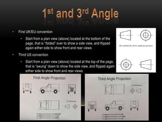
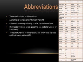
The document discusses engineering drawing standards and conventions. It explains that engineering drawings use symbols, abbreviations, and numbering systems to efficiently convey important information about materials, dimensions, and views. Standards organizations like the American Standards Association, BSI, and ISO work to establish common international standards for the production of clear, consistent engineering drawings.

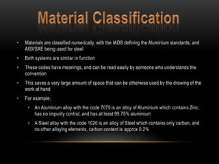
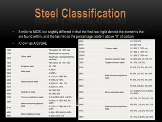
![• They are coded using the the International Alloy Designation System (IADS) standard
• The digit "1" as in 1xxx designates alloy free (no alloys) and is at least 99% Aluminium.
• The Digit is interchangeable, and depending on it’s value, it means there is a different
alloy that is also within the aluminium, some contain multiple major alloys, they are as
follows:
• “2” for Copper (Cu), “3” for Manganese (Mn), “4” for Silicon (Si), “5” for Magnesium, “6” for
Magnesium and Silicon (Mg and Si), “7” for Zinc (Zn), “8” for an unspecified alloy
(including Lithium [Li])
• The second part x0xx denotes the purity control of the Aluminium, where “0” is no control,
and “1-9” are different controls set at the mill, these levels are set by AIDS
• The final part is the minimum Aluminium percentage above 99%. So xx25 means “99.25%
minimum Aluminium content”](https://image.slidesharecdn.com/symbolsandabbreviations-141023075415-conversion-gate02/85/Symbols-and-abbreviations-7-320.jpg)