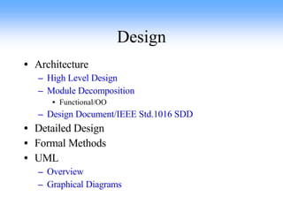
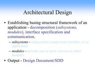
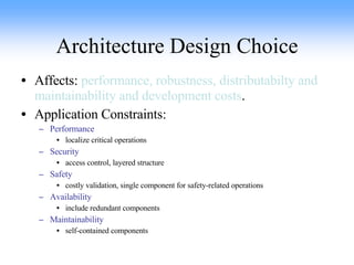
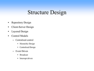
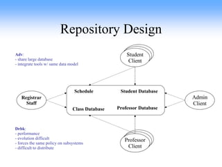
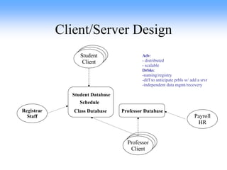
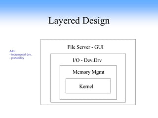
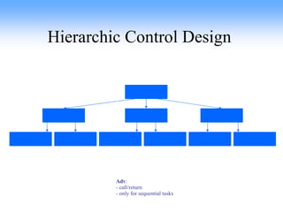
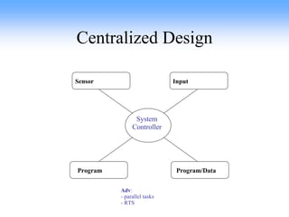
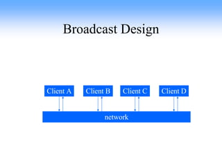
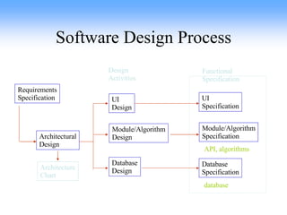
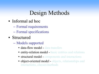
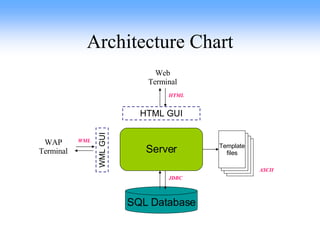
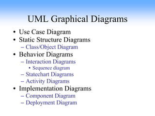
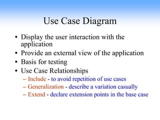
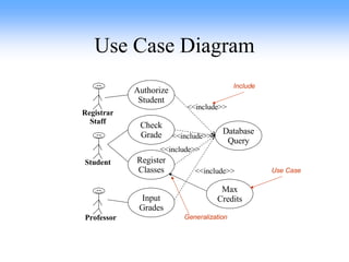
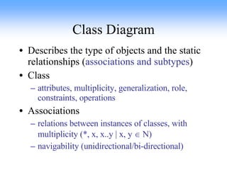
The document provides an overview of software design concepts including architectural design, design choices, structure designs, repository designs, client-server designs, layered designs, control models, design entities, software design processes, design methods, formal design approaches, and unified modeling language (UML) diagrams. It discusses topics such as decomposition, interfaces, performance, security, and maintainability as they relate to software design.
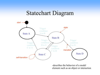
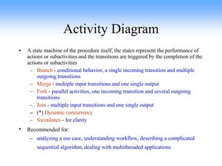
![Activity Diagram Present lecture Prepare slides Turn on the projector Tune the projector [found projector] [no projector] Use blackboard Begin lecture Start Fork Join End](https://image.slidesharecdn.com/swsoftwaredesign-1208208892799740-8/85/Sw-Software-Design-44-320.jpg)