The document summarizes the phases of the software development life cycle (SDLC) and provides details about system requirement specification for an army management system project. It describes the typical phases in SDLC models such as waterfall, spiral, agile etc. It then covers the specific phases in more detail - preliminary analysis, system analysis, design, development, integration and testing, acceptance and deployment, maintenance. Lastly, it discusses system requirement specification, including UML notations, diagrams to be used and provides a brief overview of class diagrams.
![2012 - 13
OBJECTORIENTEDANALYSISANDDESIGN
(O.O.A.D) SUBJECT
CODE:140703
DEPARTMENT OF COMPUTER SCIENCE & ENGG
DR. JIVRAJMEHTA INSTITUTE OF TECHNOLOGY
MOGAR,ANAND
[LAB MANUAL]
COMPUTERSCIENCE & ENGINEERING–SEMESTER04](https://image.slidesharecdn.com/ooadlabmanualoriginal-120729112330-phpapp02/85/Ooad-lab-manual-original-1-320.jpg)
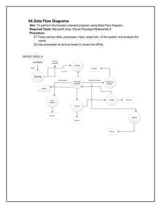
![02 .Phases in Software Development
Aim: Phases in software development project, overview, need, coverage of topics
Required Tools: None
Procedure:
1. Study different Software Development Life Cycles using your resources and
describe each phase briefly.
2. You can take help of different book sand online resources available on
internet.
The SDLC is a process used by a systems analyst to develop an
information system, training, and user (stakeholder) ownership. Any
SDLC should result in a high quality system that meets or exceeds
customer expectations, reaches completion within time and cost
estimates, works effectively and efficiently in the current and planned
Information Technology infrastructure, and is inexpensive to maintain
and cost-effective to enhance.[2] Computer systems are complex and
often (especially with the recent rise of service-oriented architecture)
link multiple traditional systems potentially supplied by different software
vendors. To manage this level of complexity, a number of SDLC models
or methodologies have been created, such as "waterfall"; "spiral"; "Agile
software development"; "rapid prototyping"; "incremental"; and](https://image.slidesharecdn.com/ooadlabmanualoriginal-120729112330-phpapp02/85/Ooad-lab-manual-original-5-320.jpg)
!["synchronize and stabilize
SDLC models can be described along spectrum of agile to iterative to
sequential. Agile methodologies, such as XP and Scrum, focus on
lightweight processes which allow for rapid changes along the
development cycle. Iterative methodologies, such as Rational Unified
Process and dynamic systems development method, focus on limited
project scope and expanding or improving products by multiple
iterations. Sequential or big-design-up-front (BDUF) models, such as
Waterfall, focus on complete and correct planning to guide large
projects and risks to successful and predictable results[citation needed].
Other models, such as Anamorphic Development, tend to focus on a
form of development that is guided by project scope and adaptive
iterations of feature development.
In project management a project can be defined both with a project life
cycle (PLC) and an SDLC, during which slightly different activities
occur. According to Taylor (2004) "the project life cycle encompasses
all the activities of the project, while the systems development life cycle
focuses on realizing the product requirements".[4] SDLC (systems
development life cycle) is used during the development of an IT project,
it describes the different stages involved in the project from the drawing
board, through the completion of the project.
Systems development phases
Preliminary analysis: The objective of phase1 is to conduct a
preliminary analysis, propose alternative solutions, describe costs
and benefits and submit a preliminary plan with
recommendations.
Conduct the preliminary analysis: in this step, you need to find out
the organization's objectives and the nature and scope of the
problem under study. Even if a problem refers only to a small
segment of the organization itself then you need find out what the
objectives of the organization itself are. Then you need to see
how the problem being studied fits in with them.
Propose alternative solutions: In digging into the organization's
objectives and specific problems, you may have already covered
some solutions. Alternate proposals may come from interviewing
employees, clients , suppliers, and/or consultants. You can also
study what competitors are doing. With this data, you will have](https://image.slidesharecdn.com/ooadlabmanualoriginal-120729112330-phpapp02/85/Ooad-lab-manual-original-6-320.jpg)
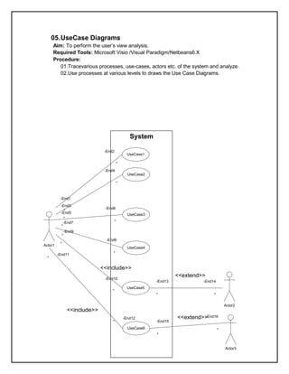
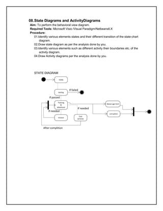
![ACTIVITY DIAGRAM
testing
-End4 *
[if failed]
-End3
*
[if passed]
training & adventure
-End2 *
[over age limit &
corruption]
[under age limit]
mission civil services
* -End1](https://image.slidesharecdn.com/ooadlabmanualoriginal-120729112330-phpapp02/85/Ooad-lab-manual-original-20-320.jpg)


![Lab manual operating system [cs 502 rgpv] (usefulsearch.org) (useful search)](https://cdn.slidesharecdn.com/ss_thumbnails/labmanualoperatingsystemcs-502rgpv-150814113808-lva1-app6892-thumbnail.jpg?width=640&height=640&fit=bounds)