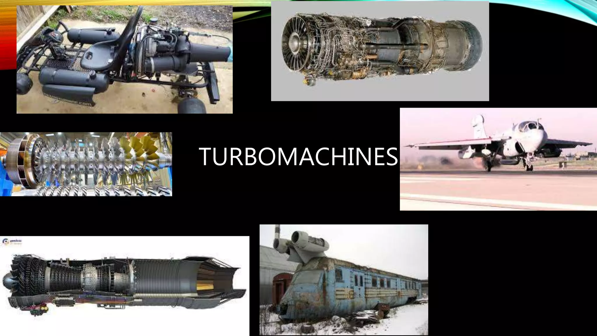
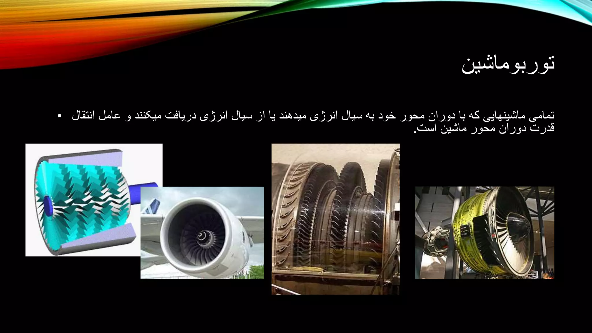
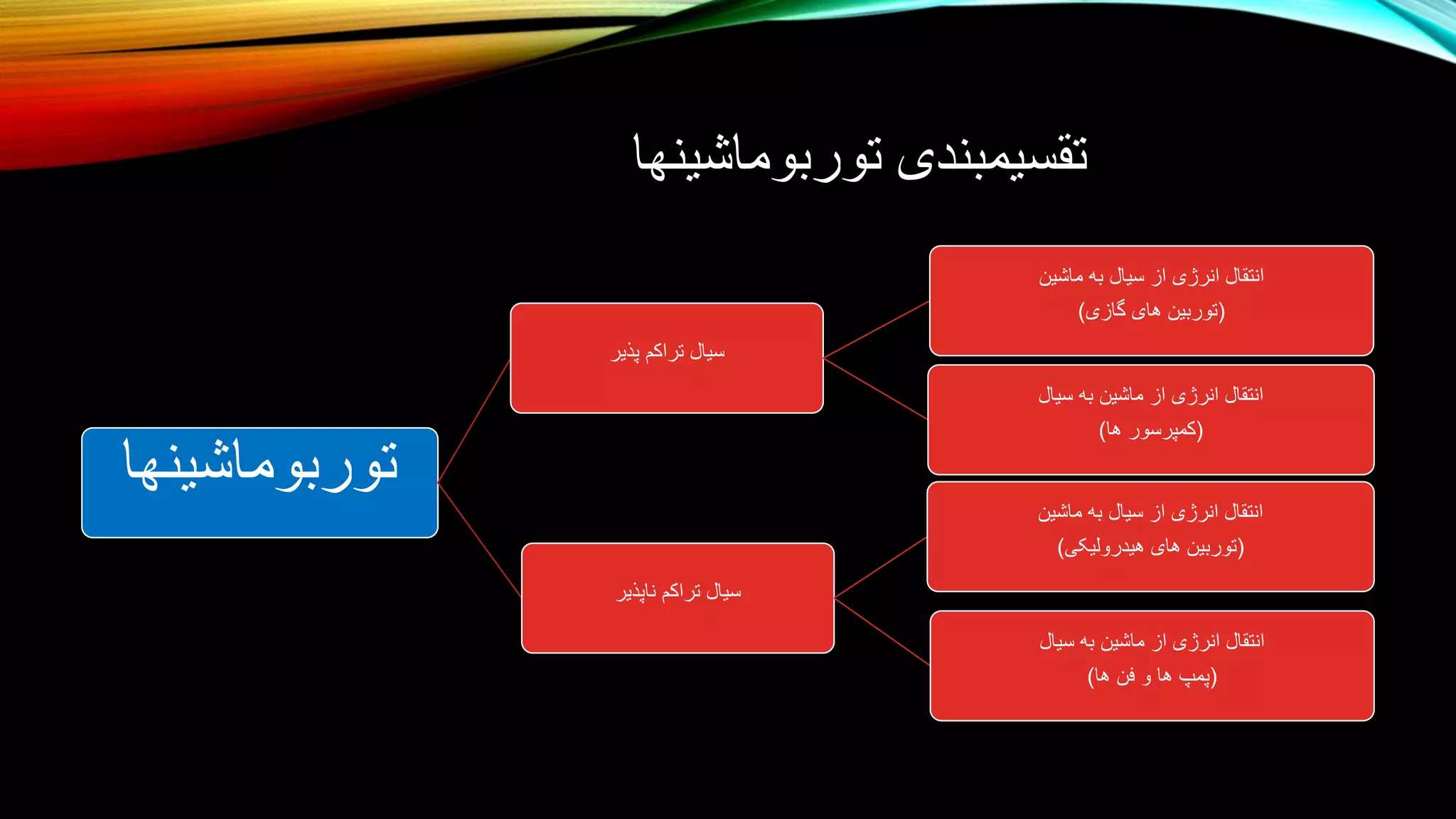
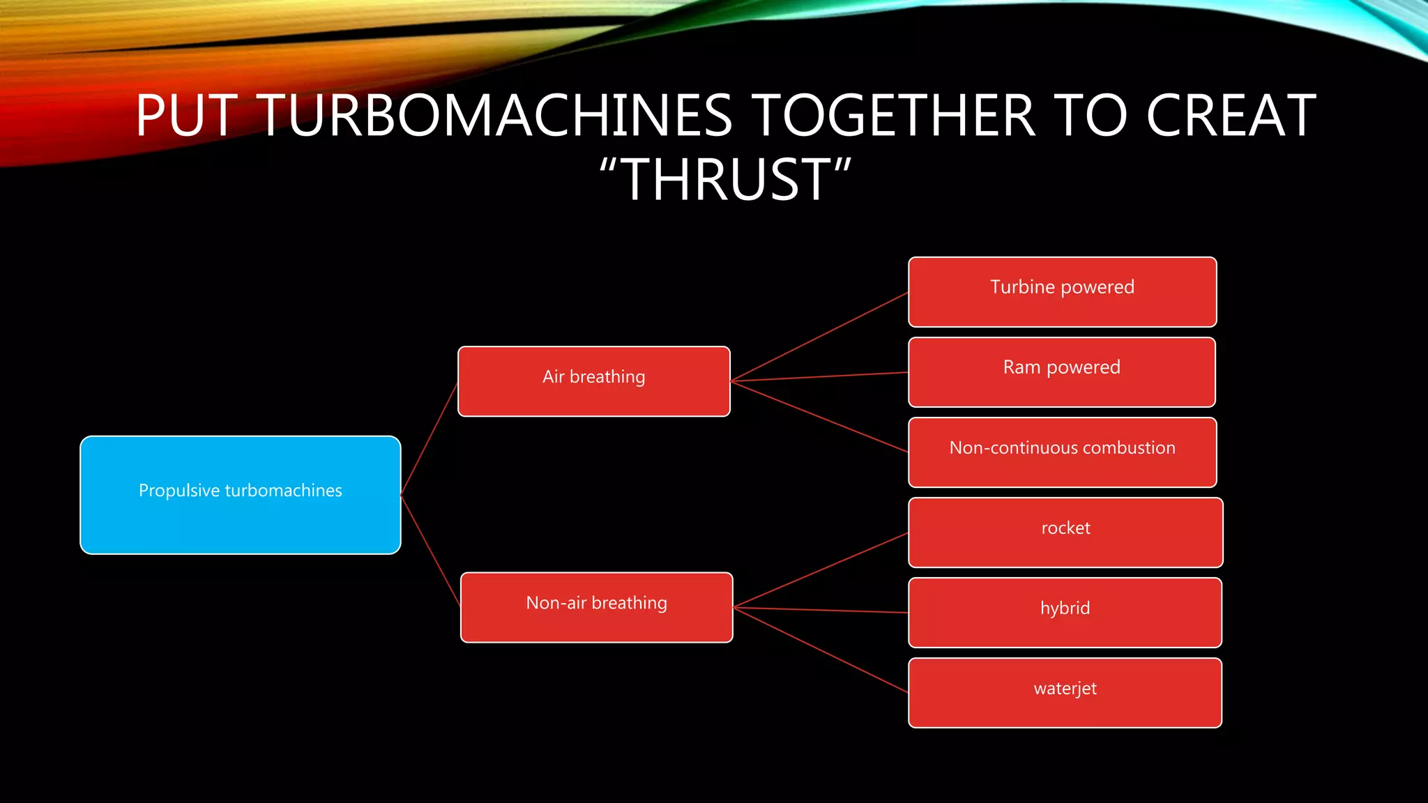
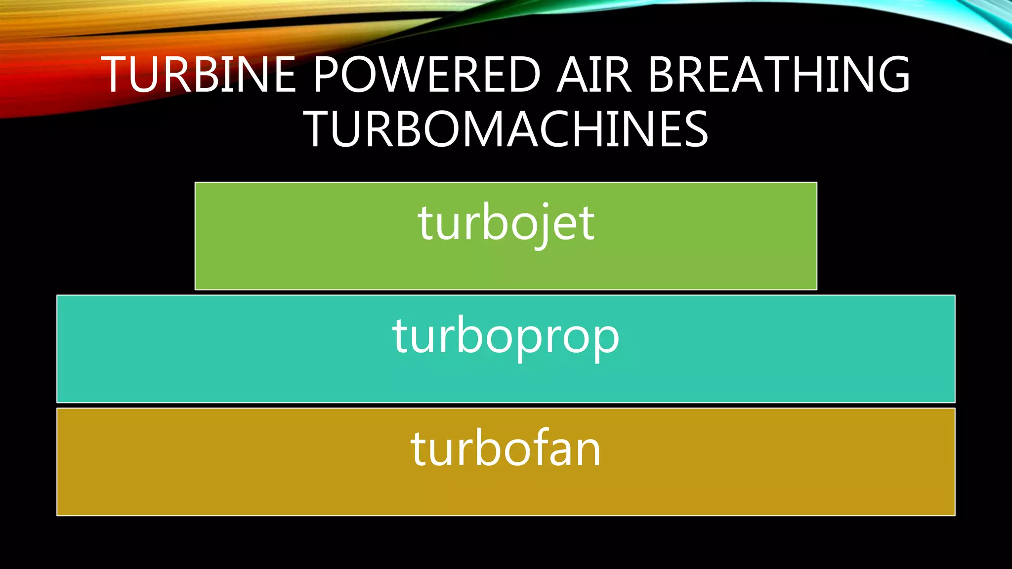
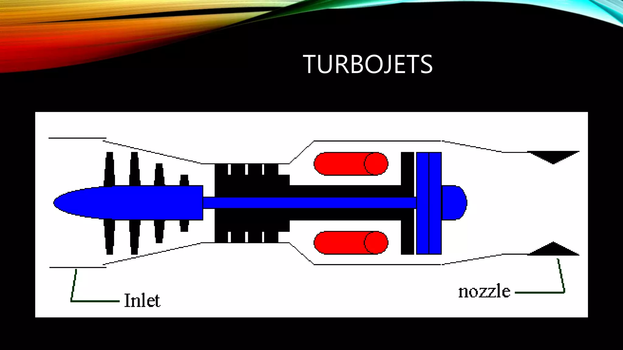
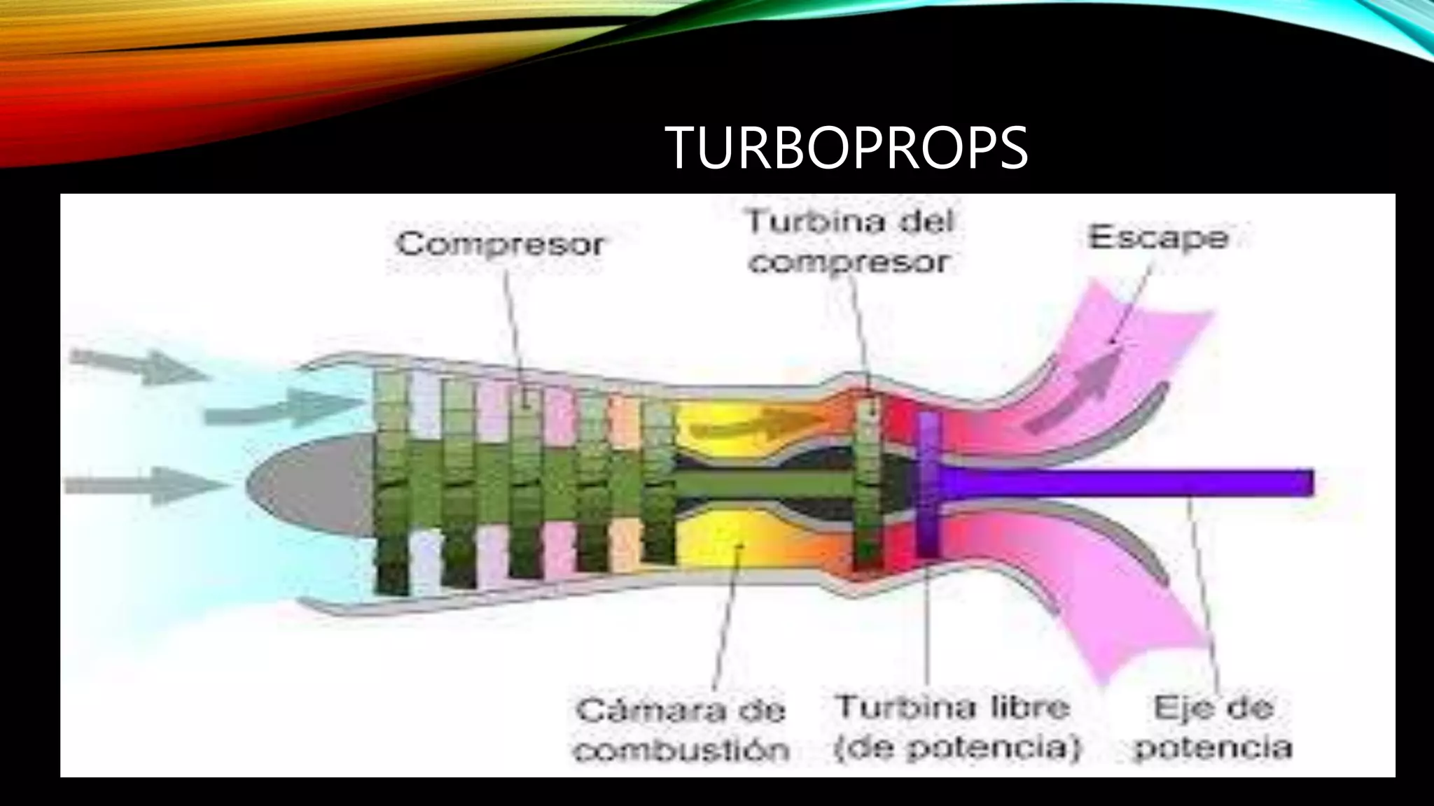
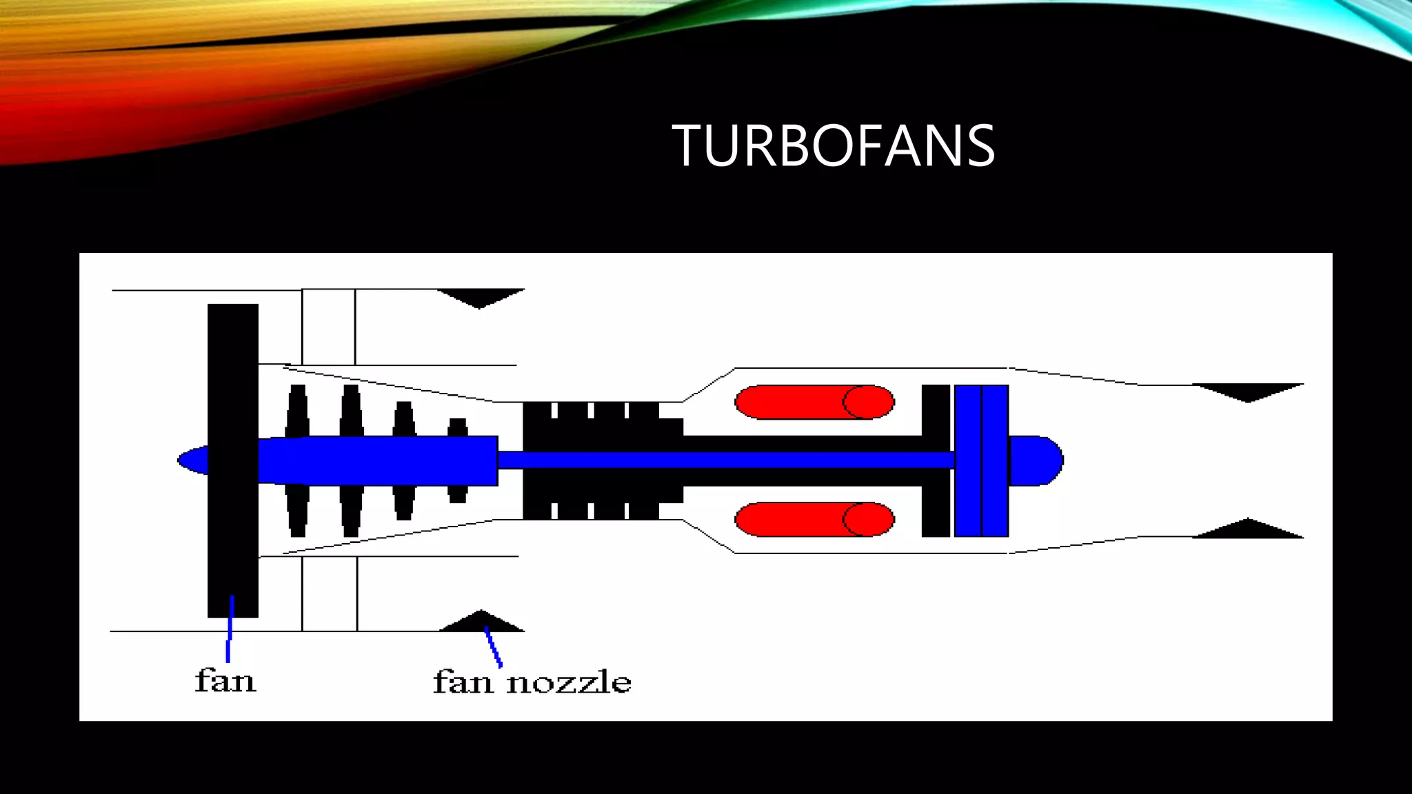
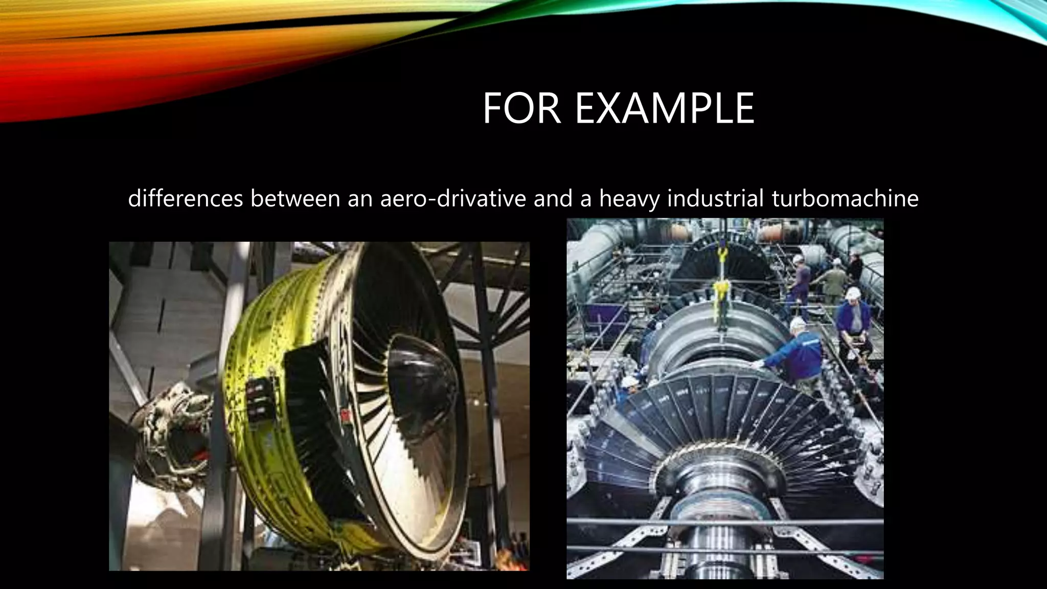
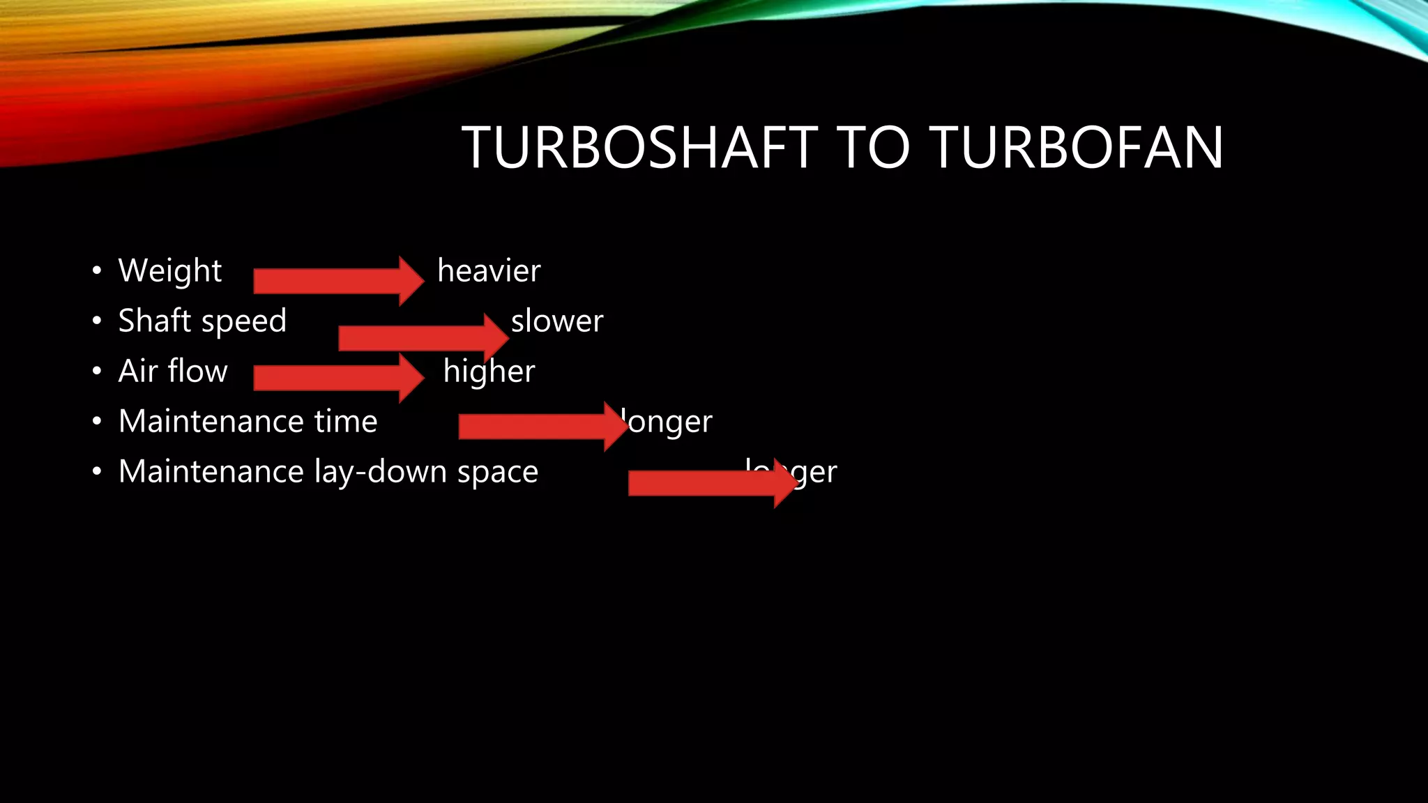
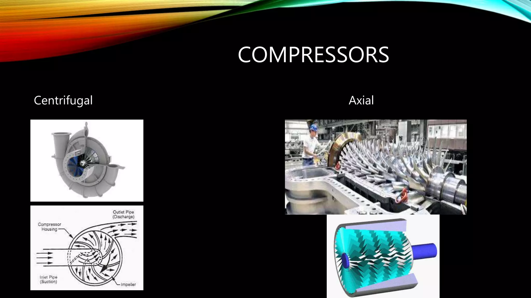
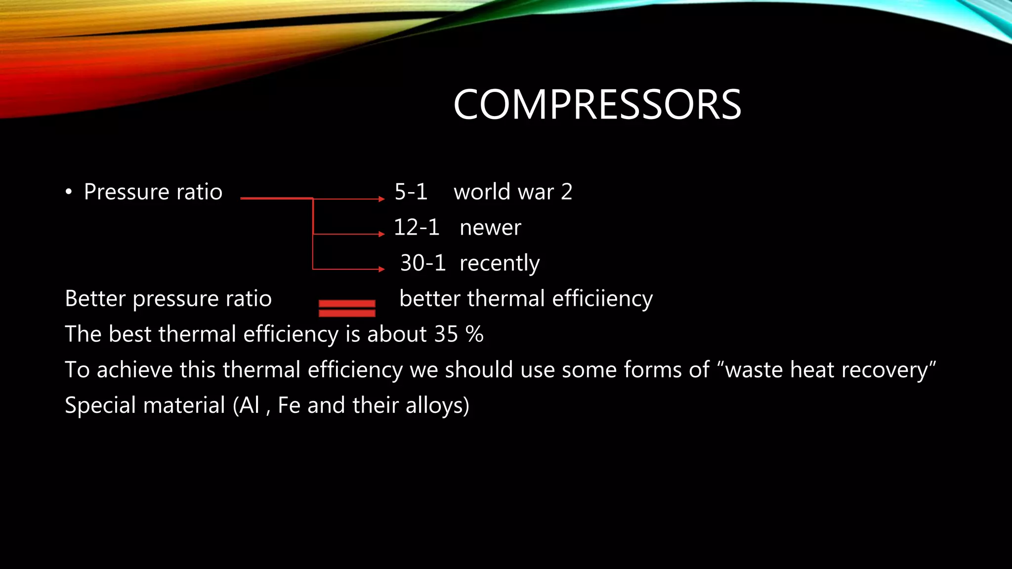
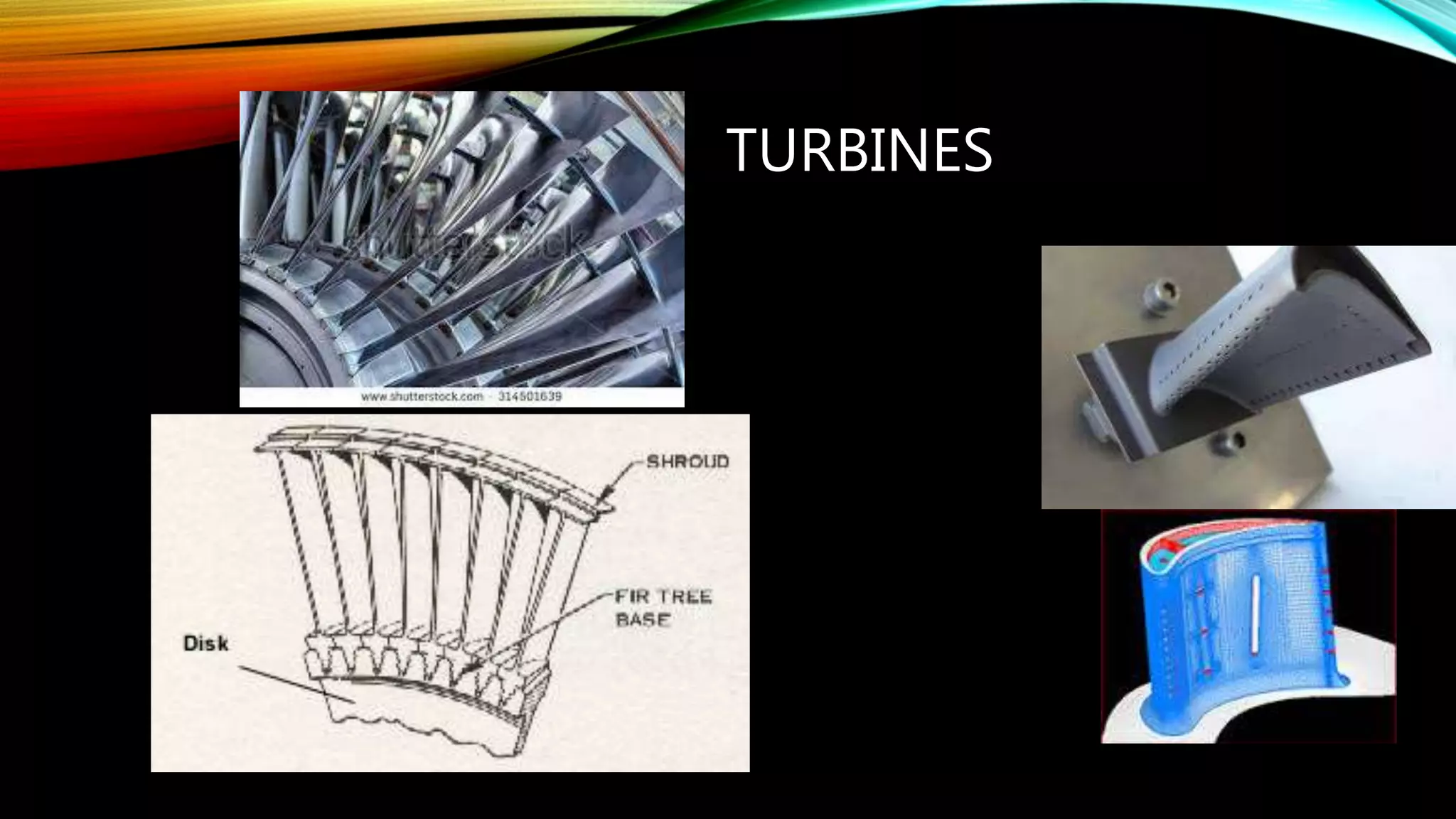
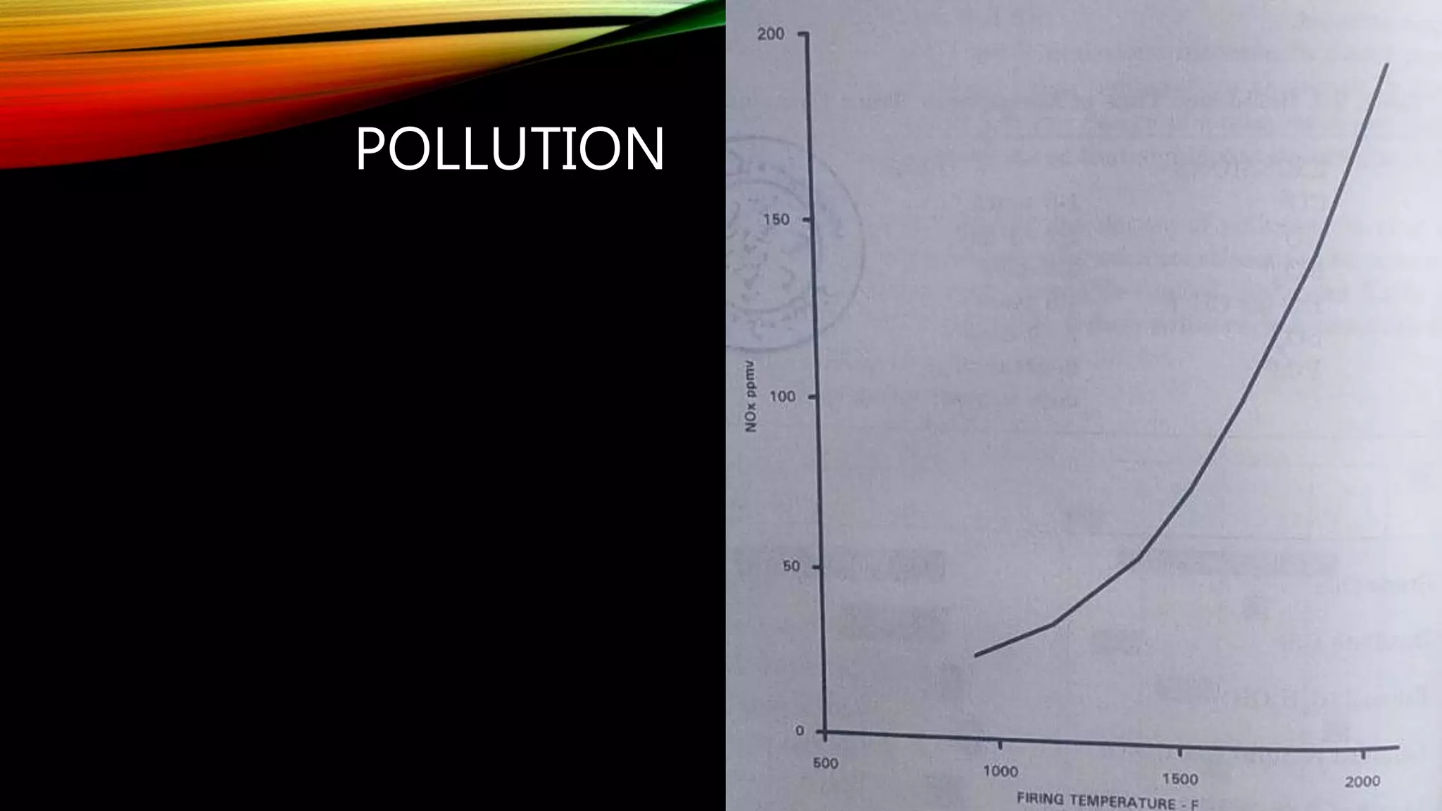
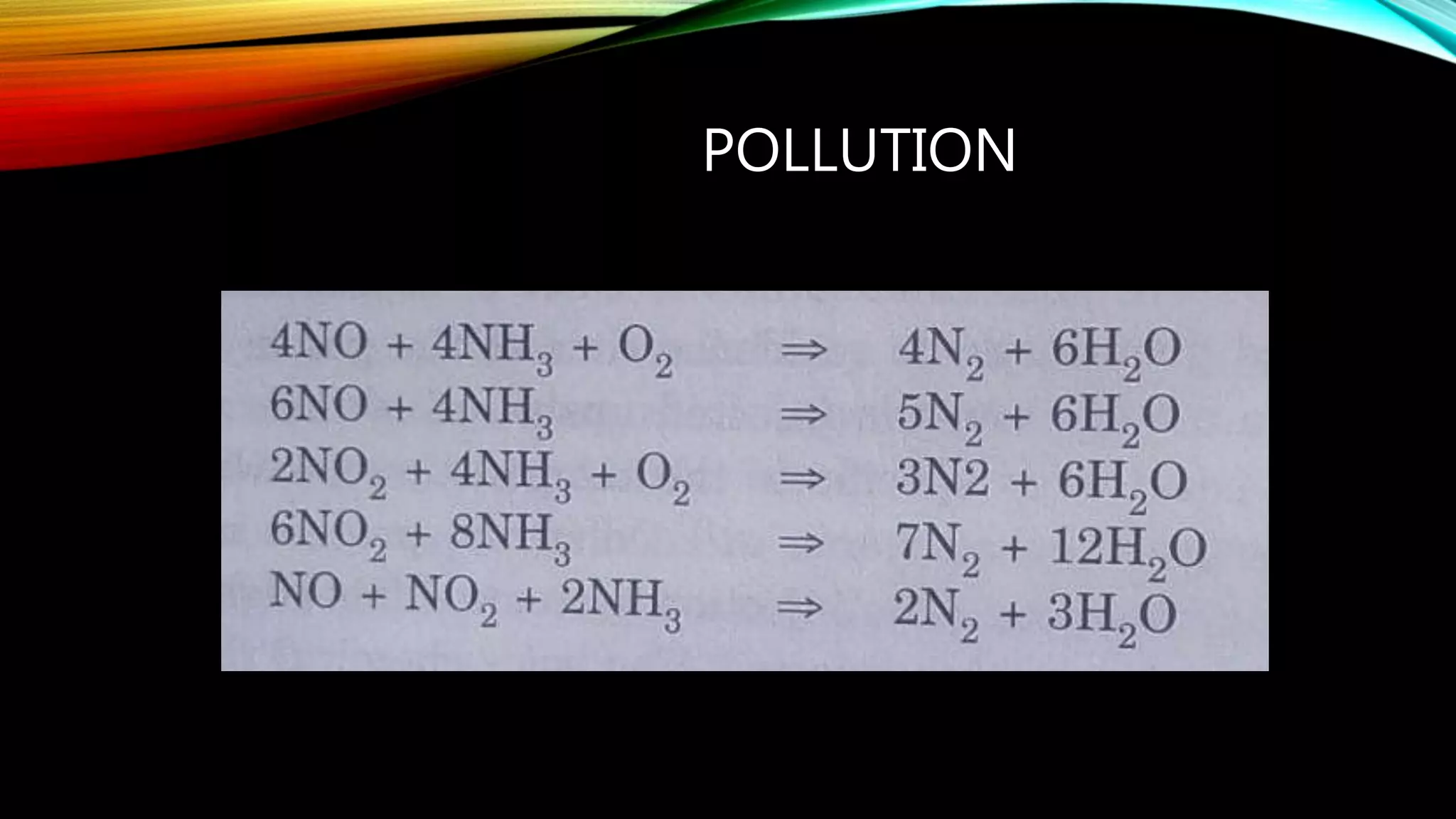
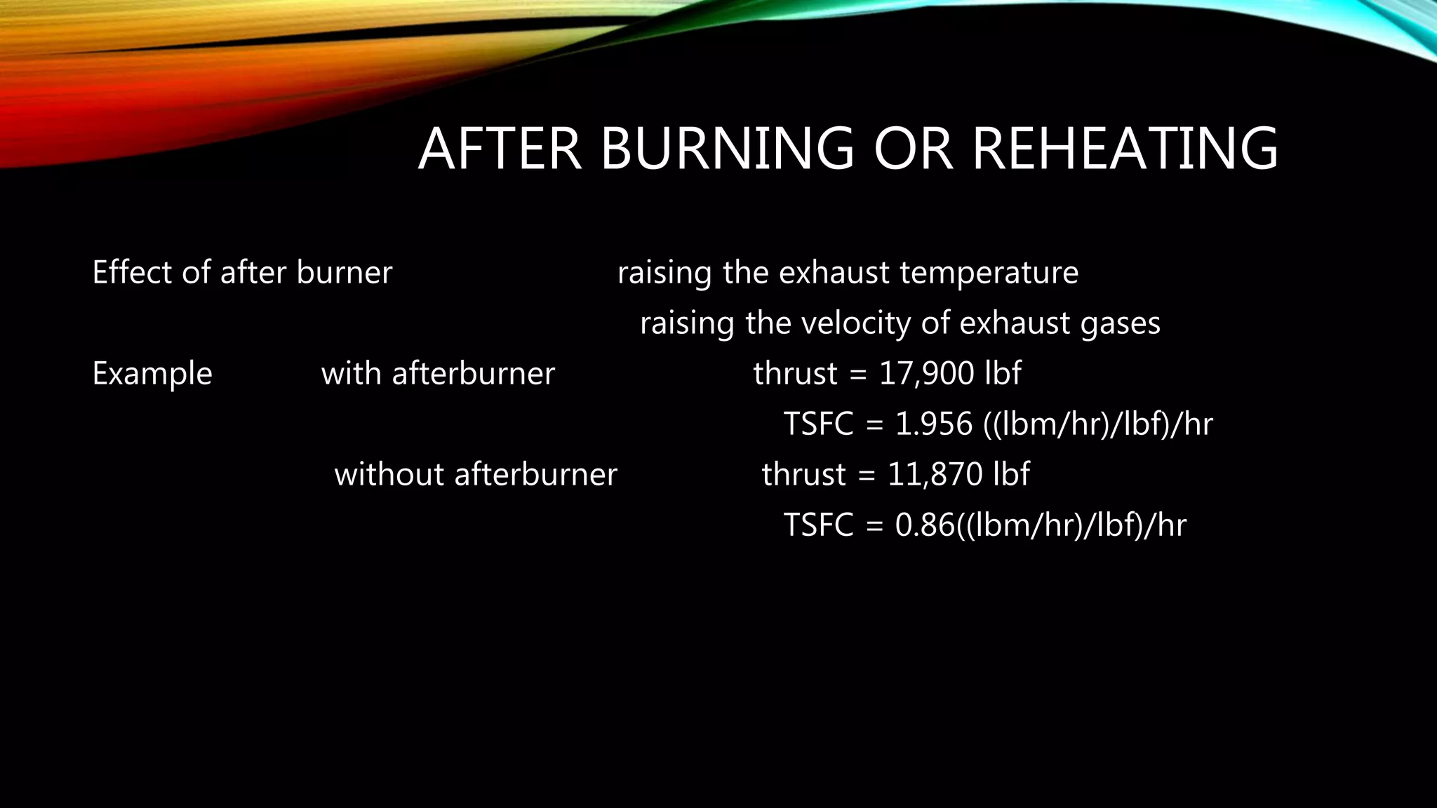
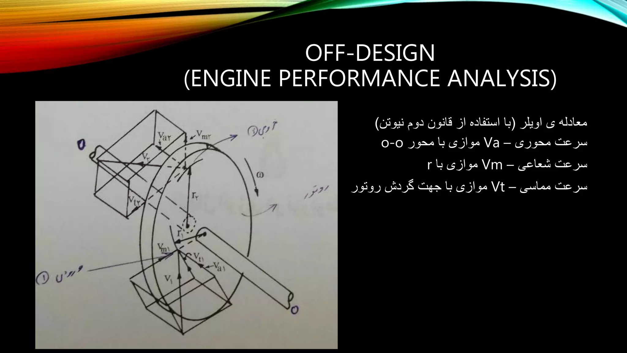
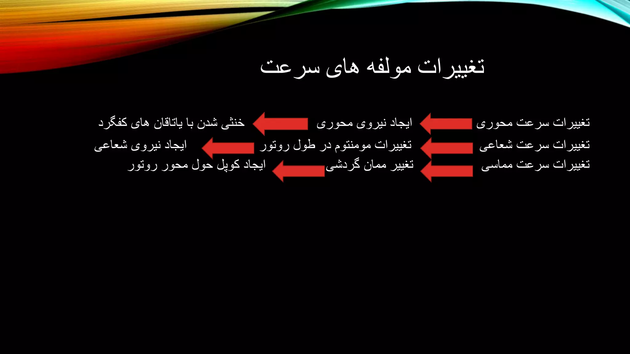
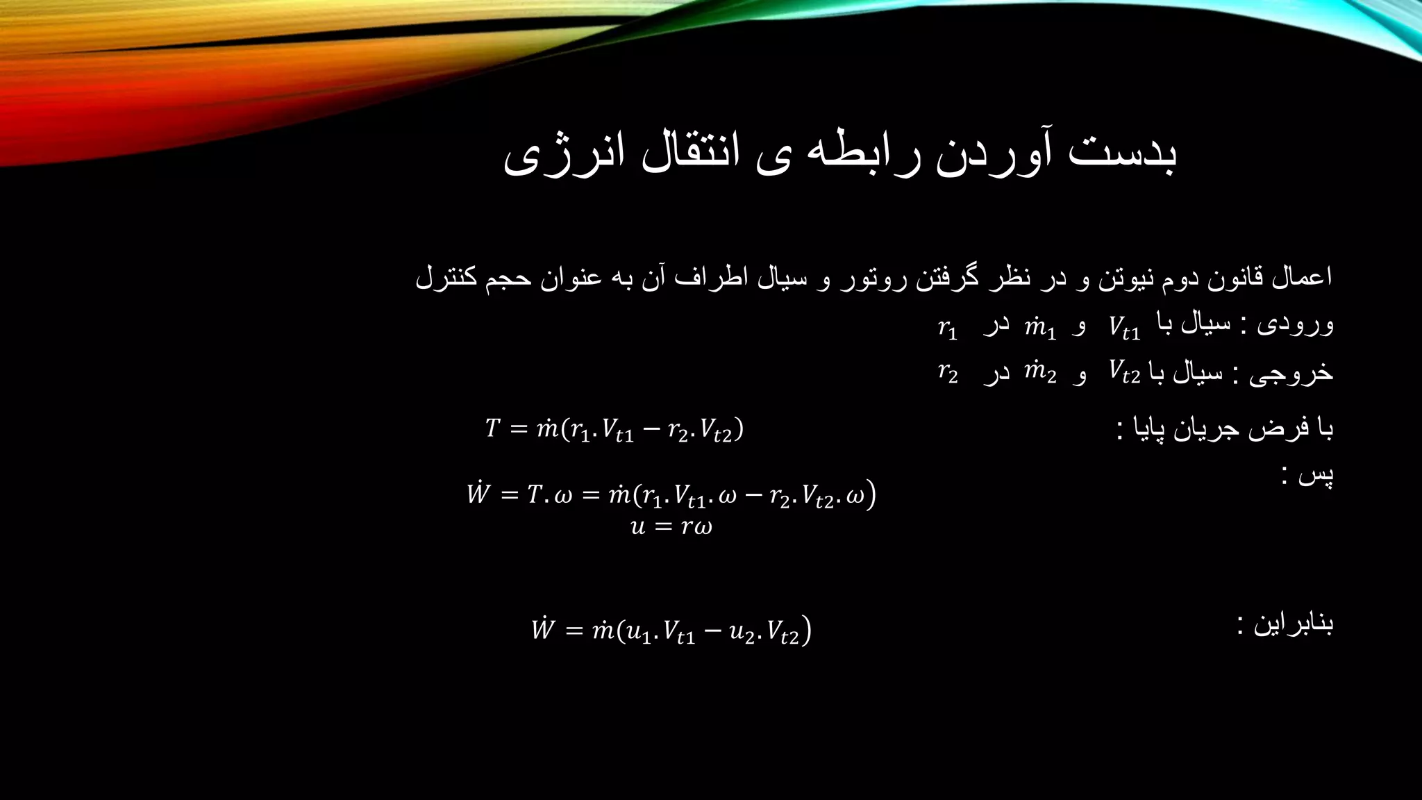
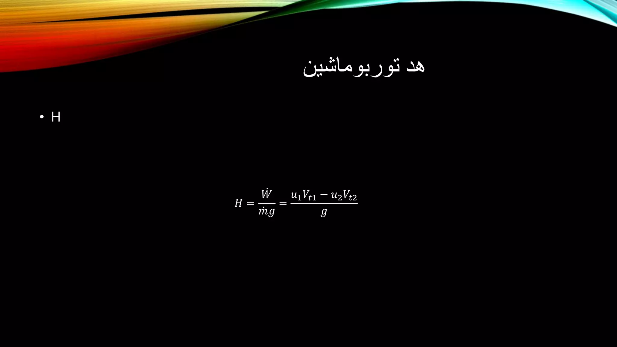
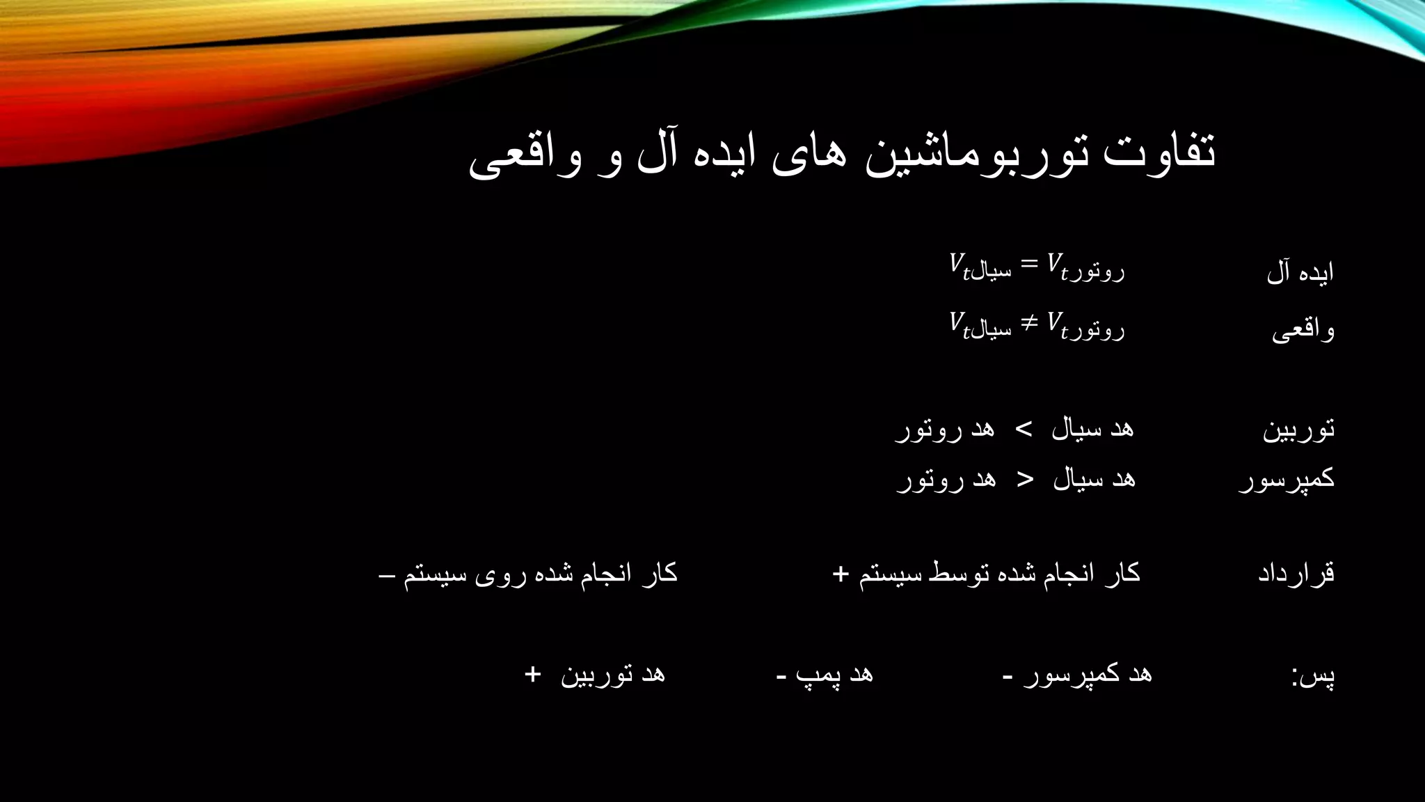
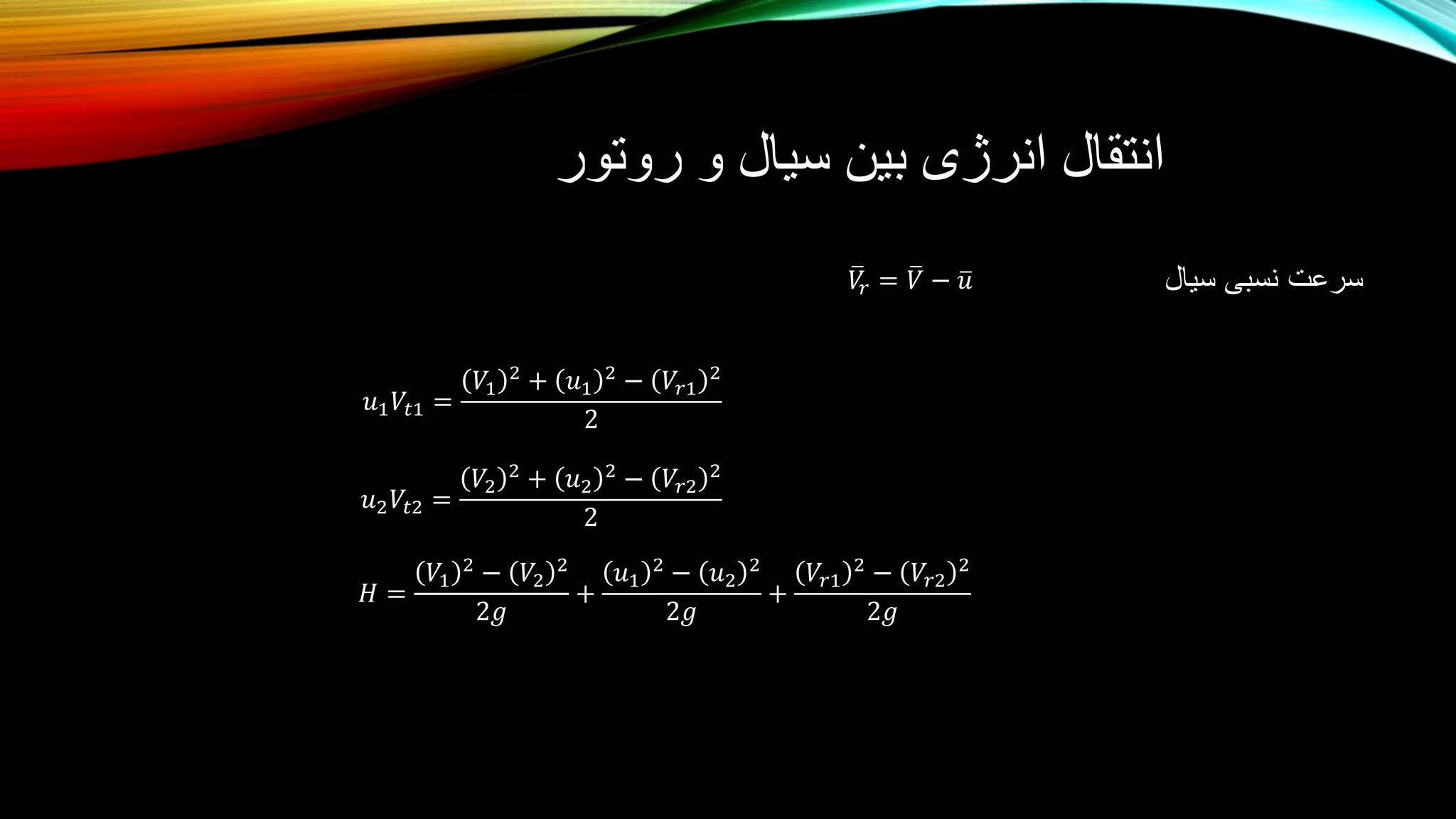
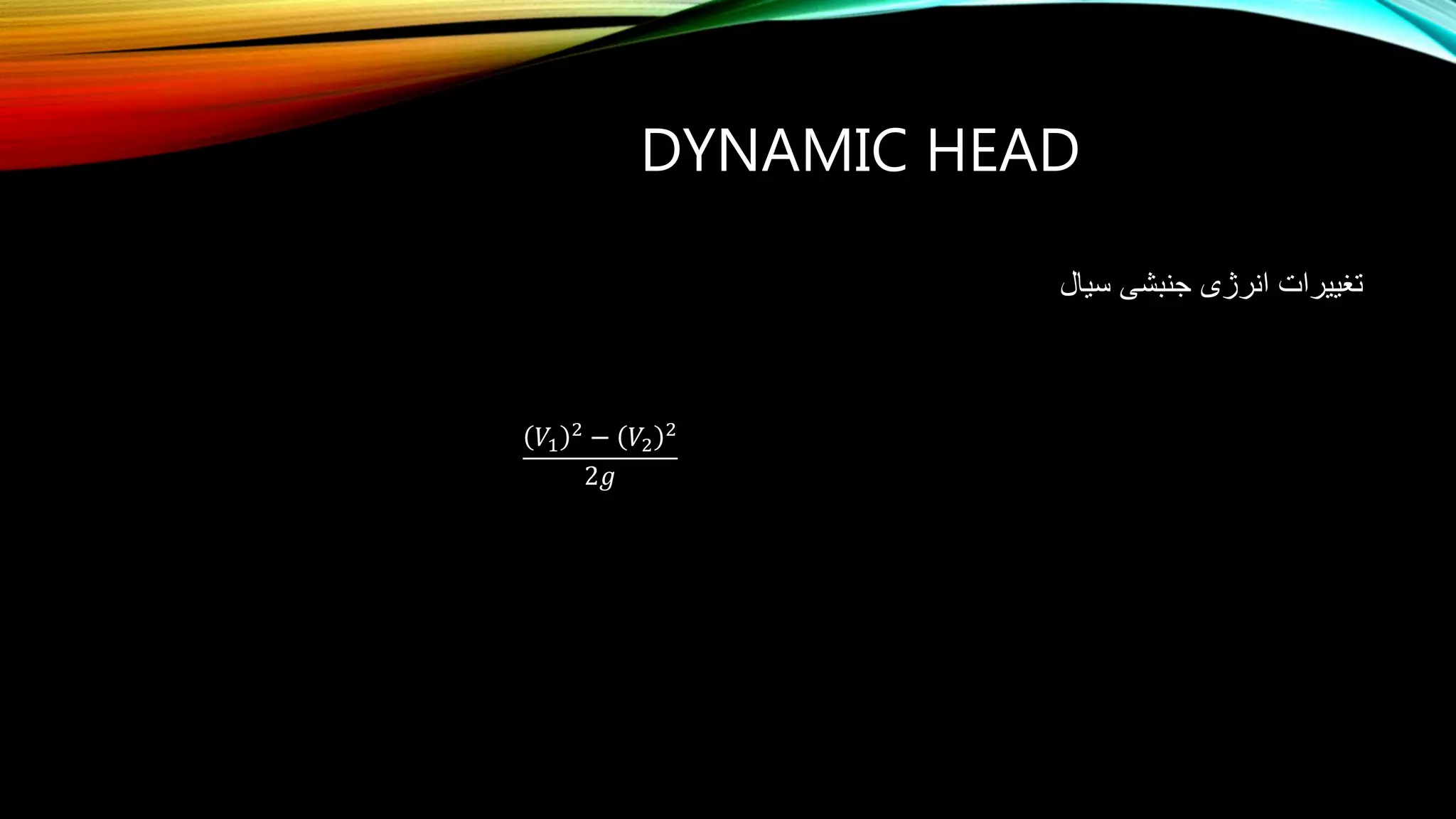
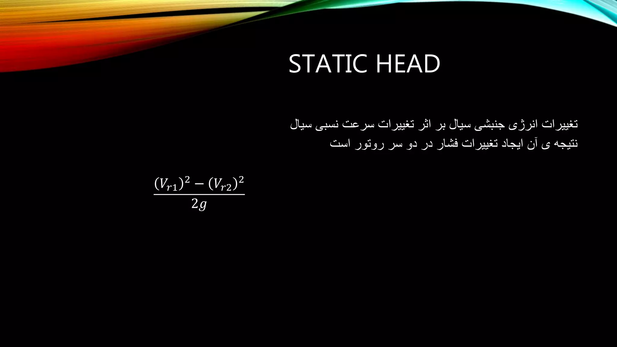
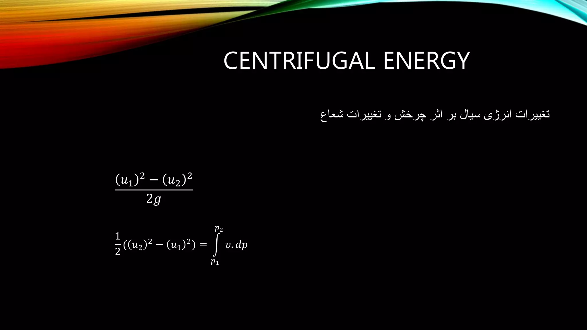
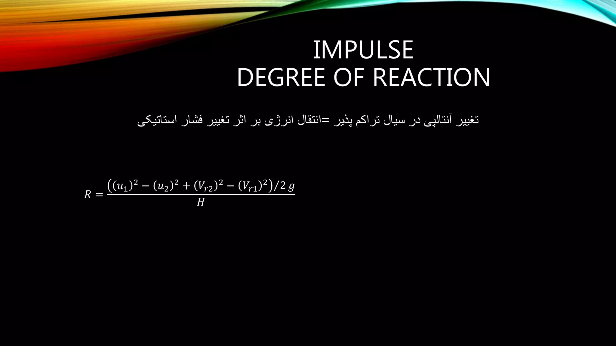
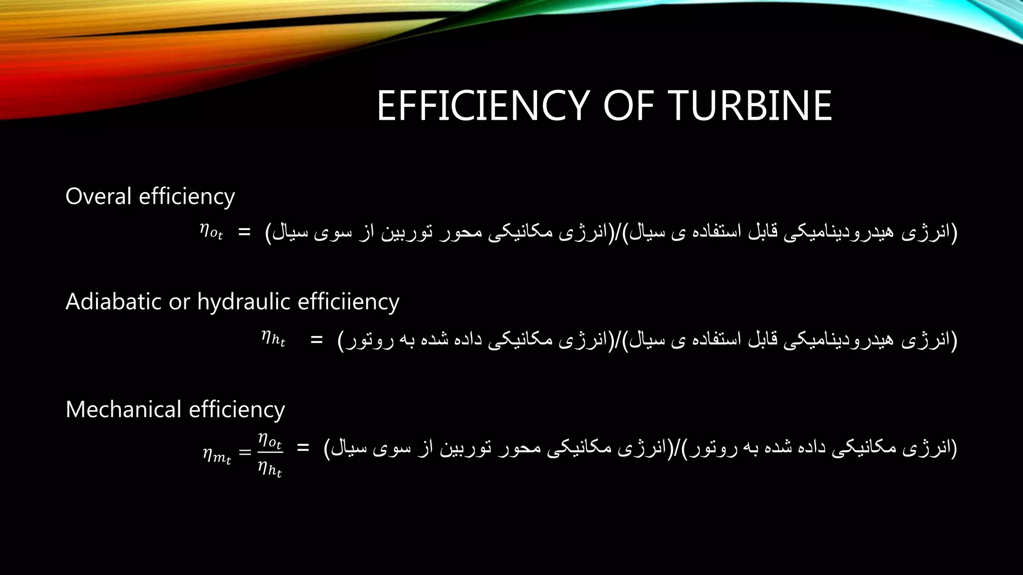
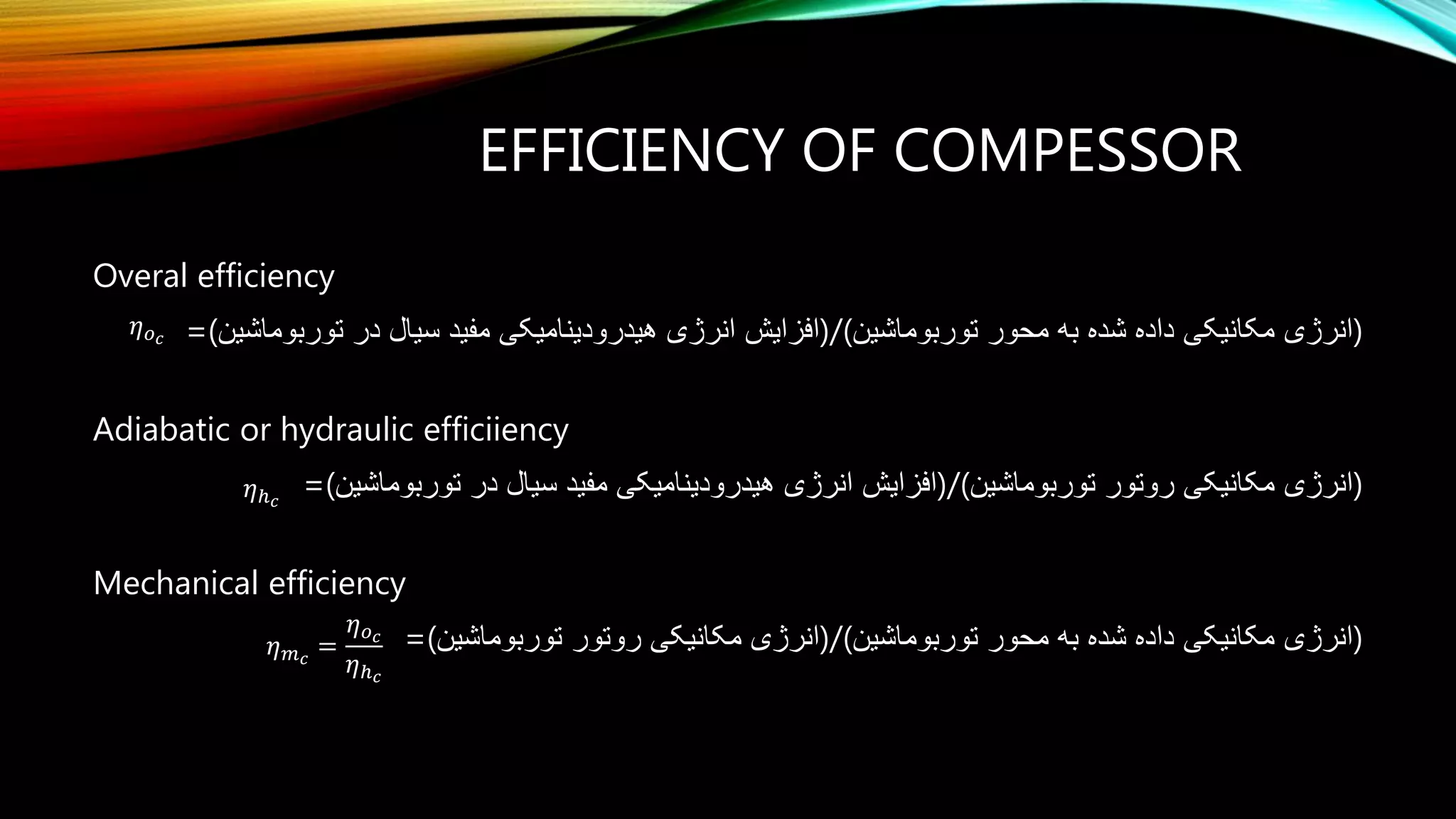
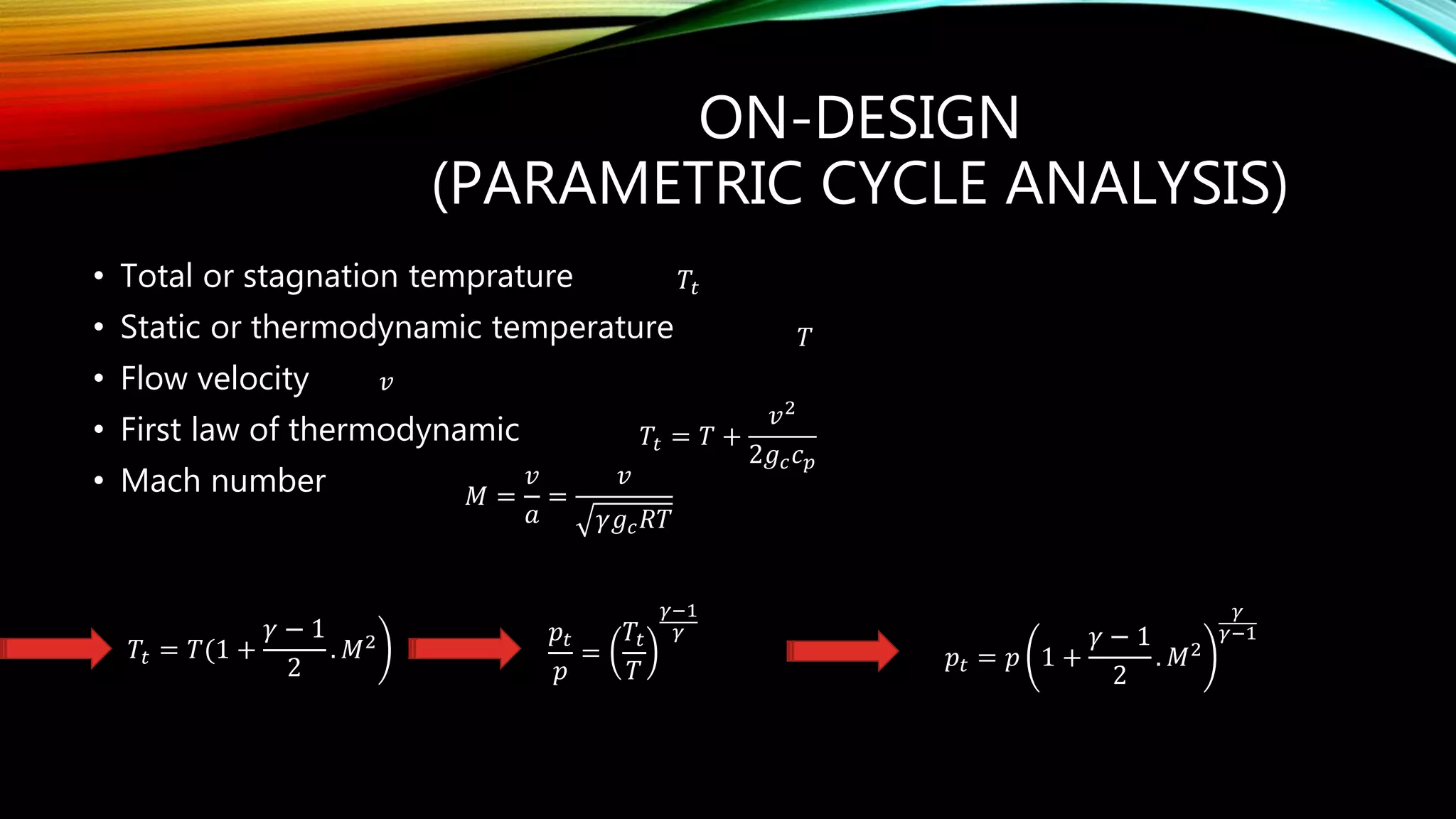
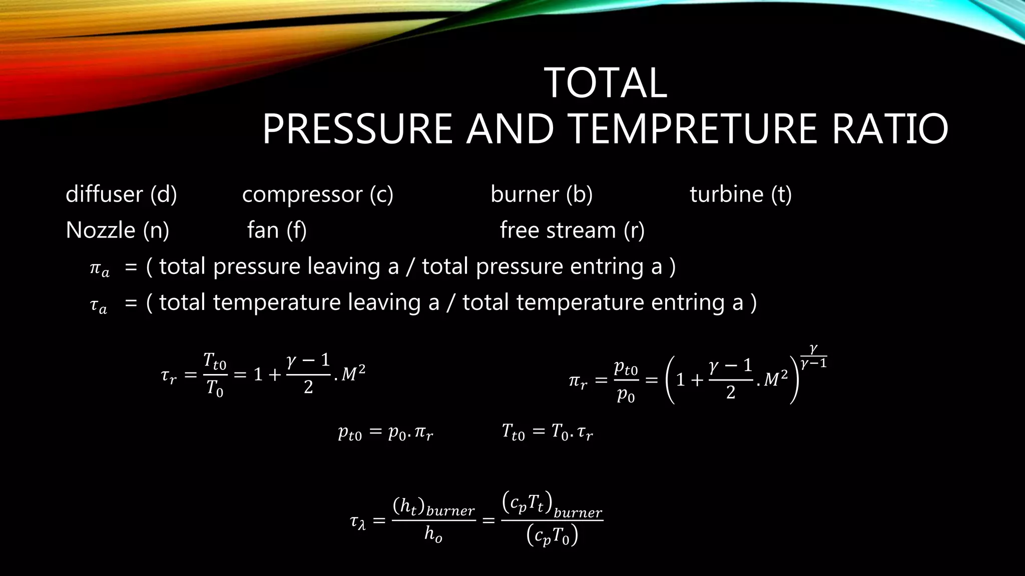
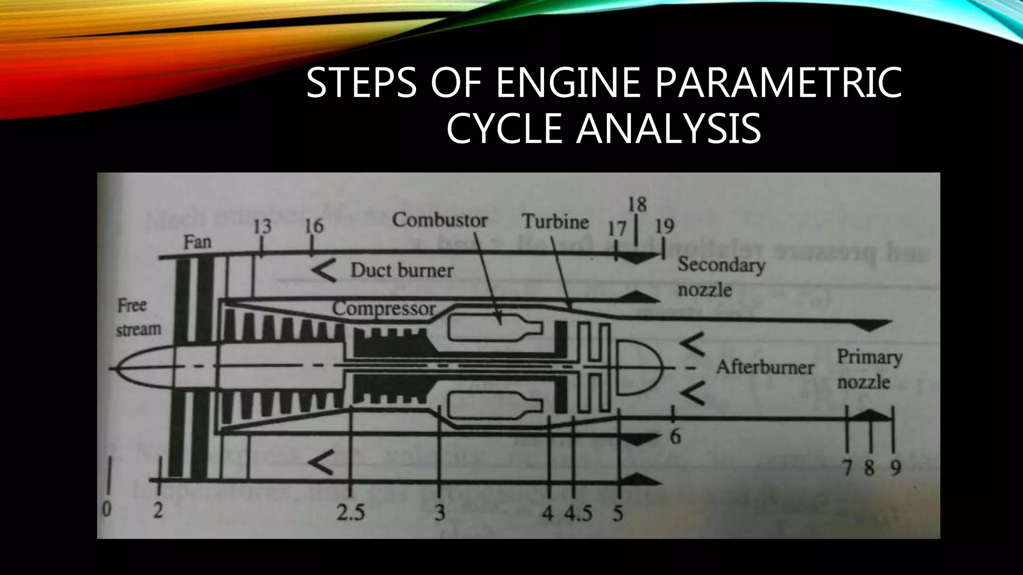
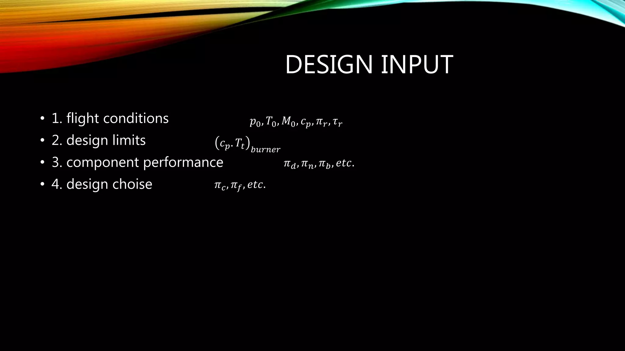
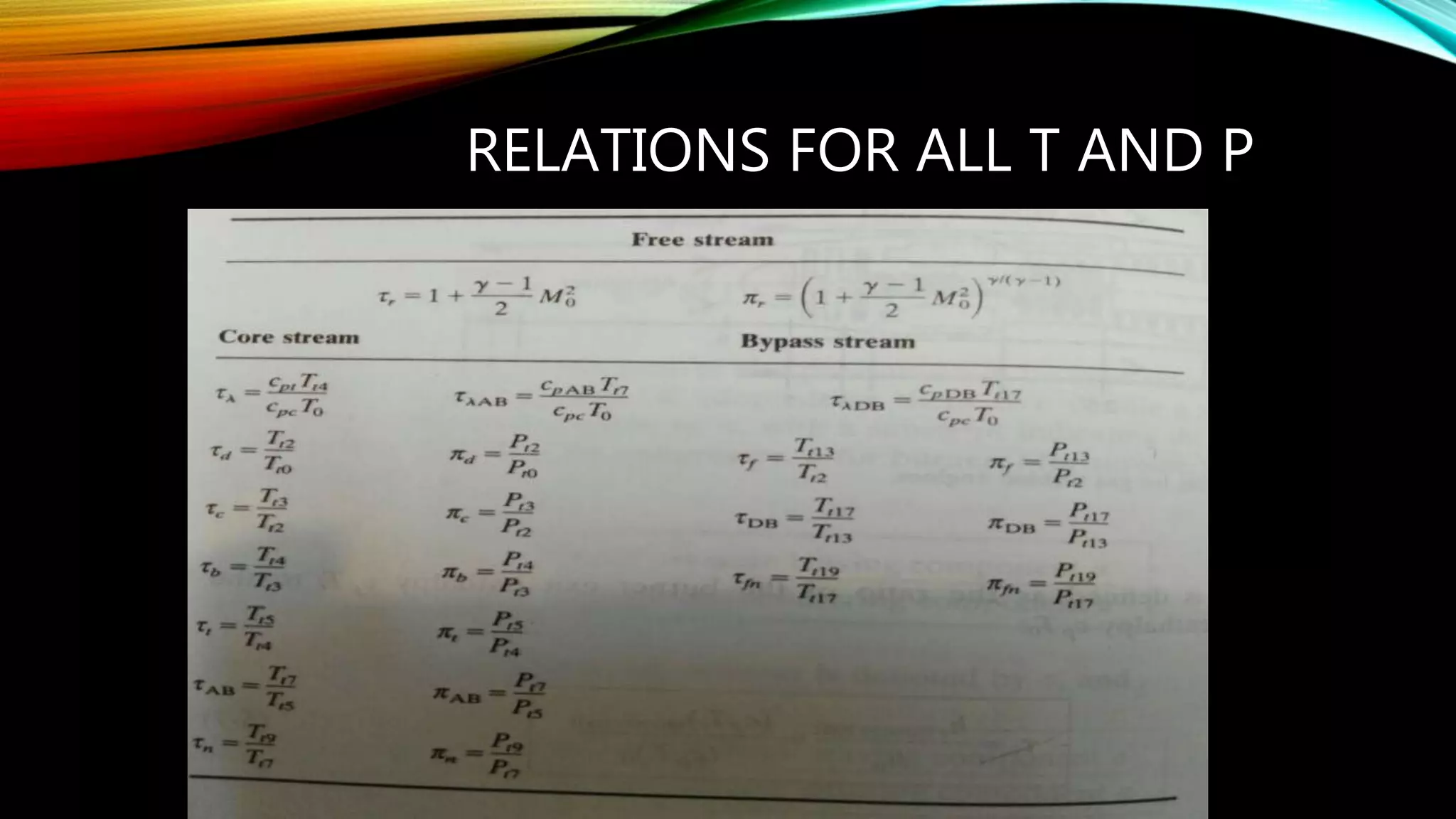
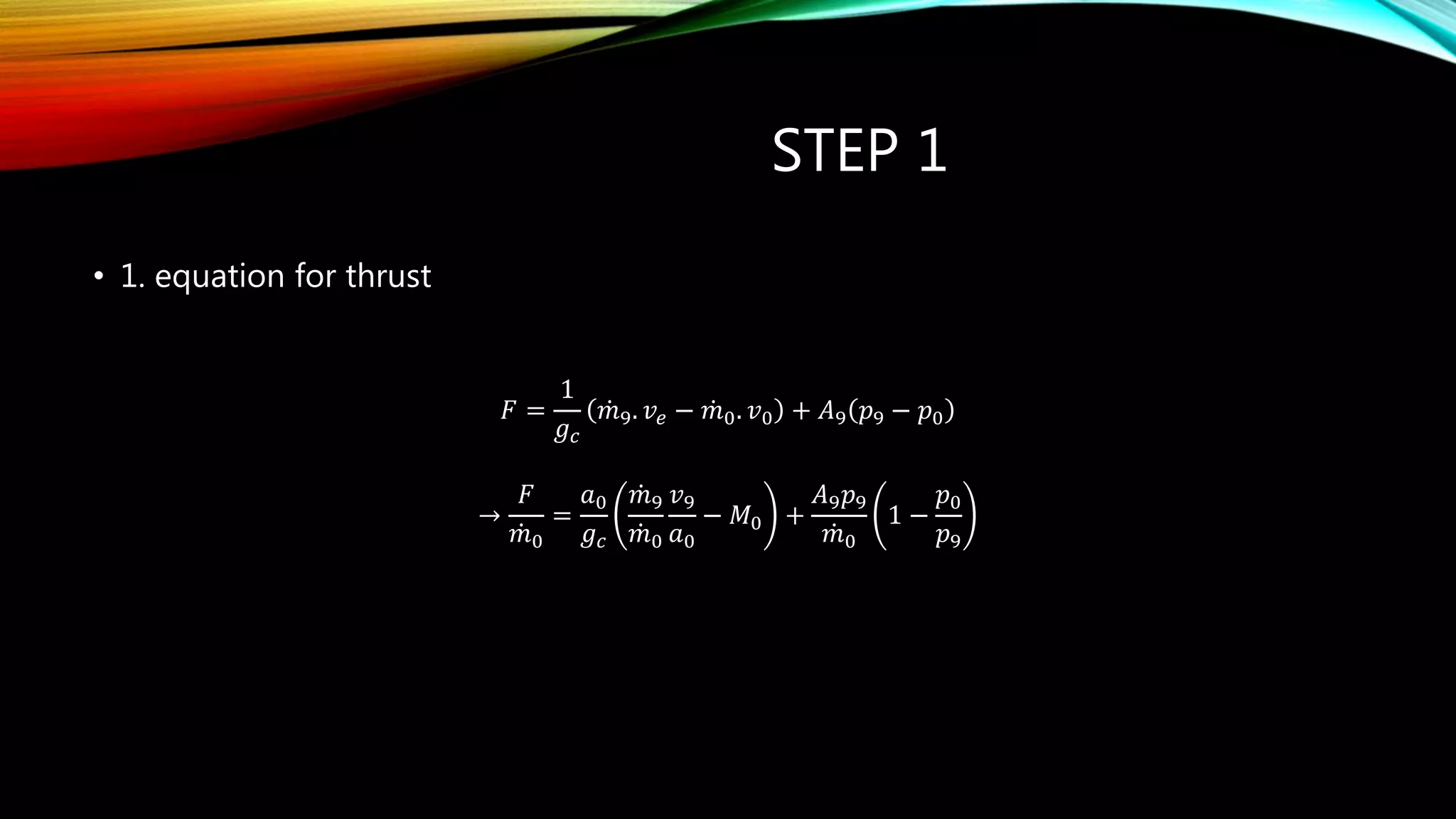
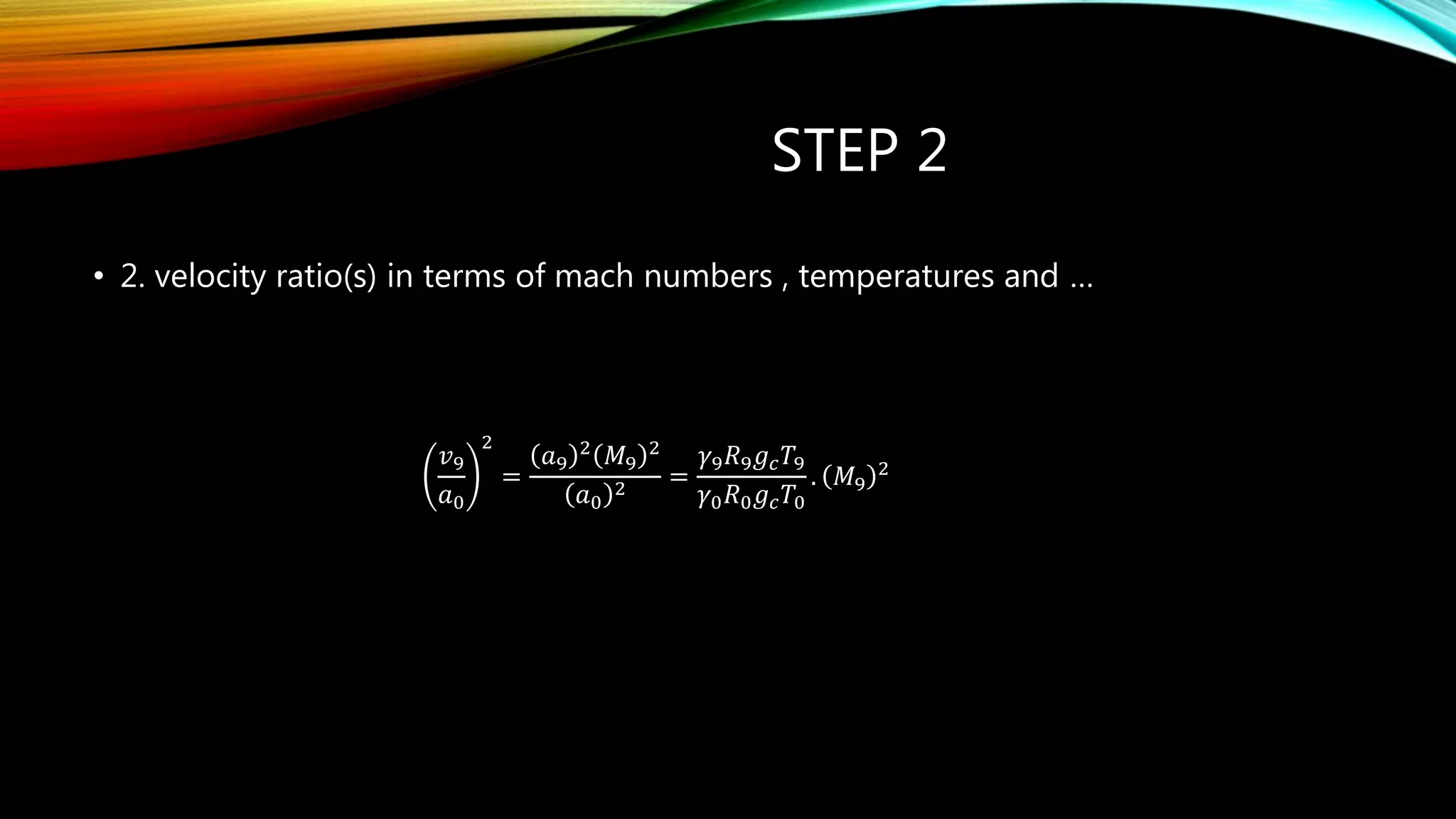
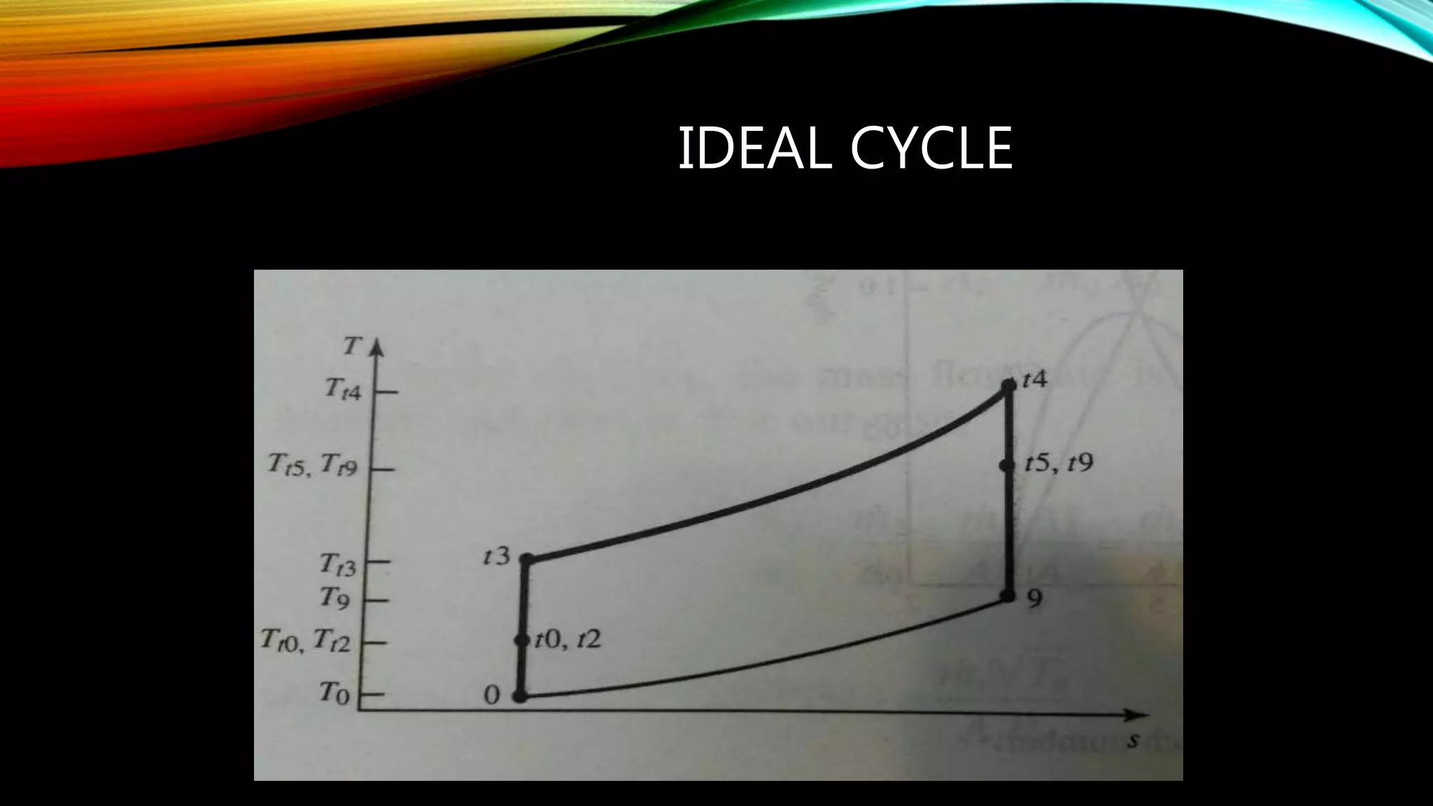
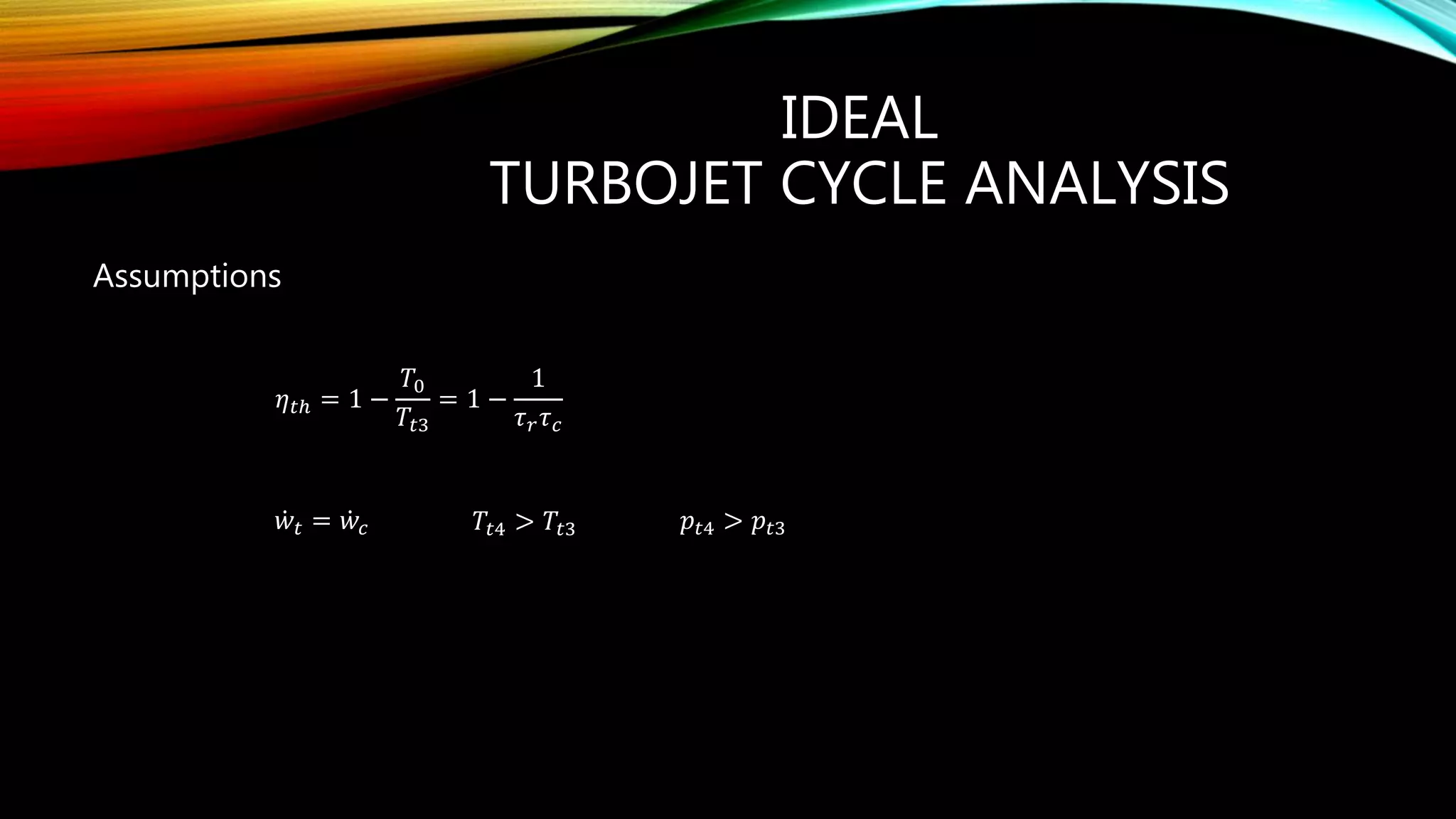
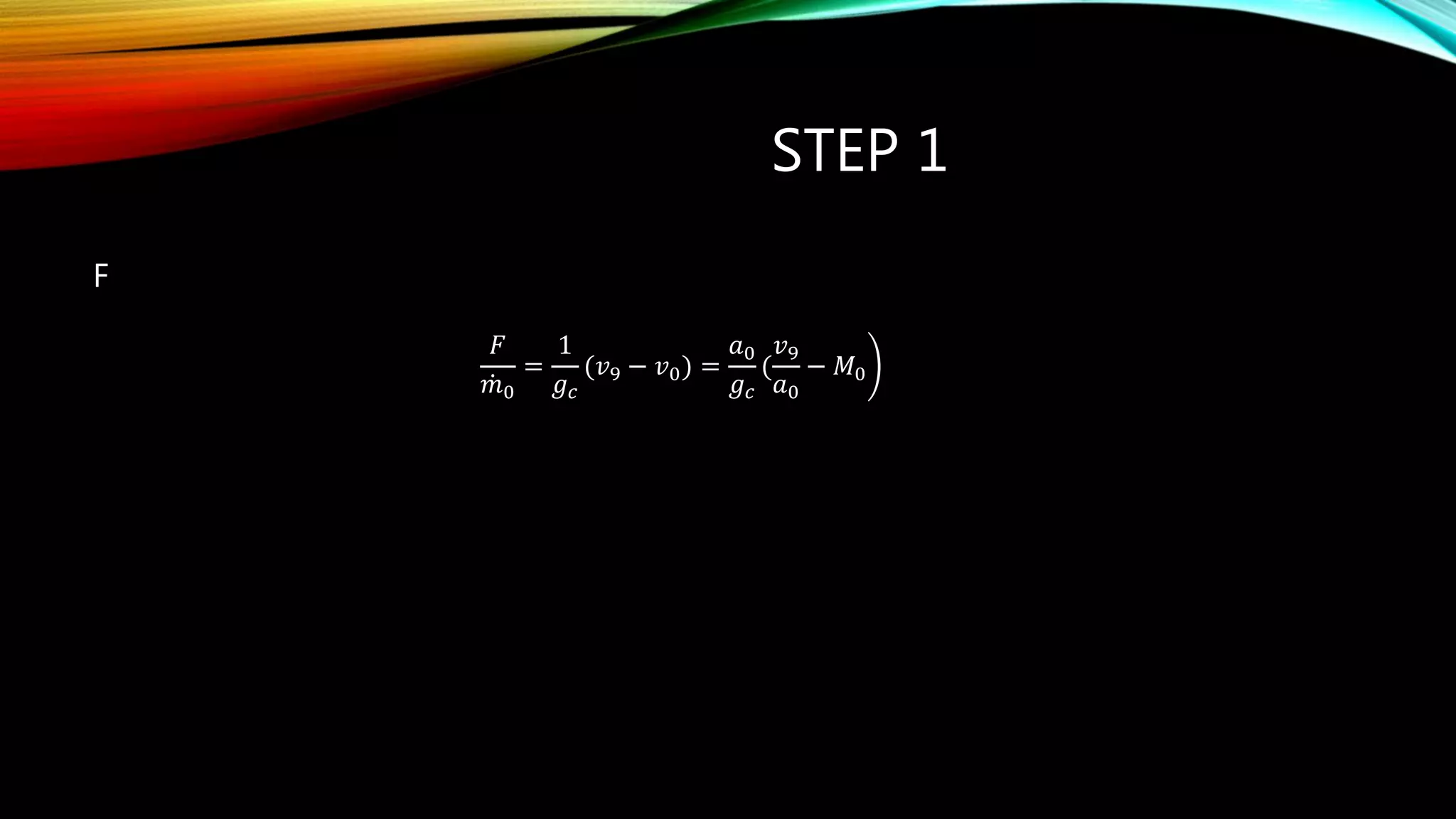
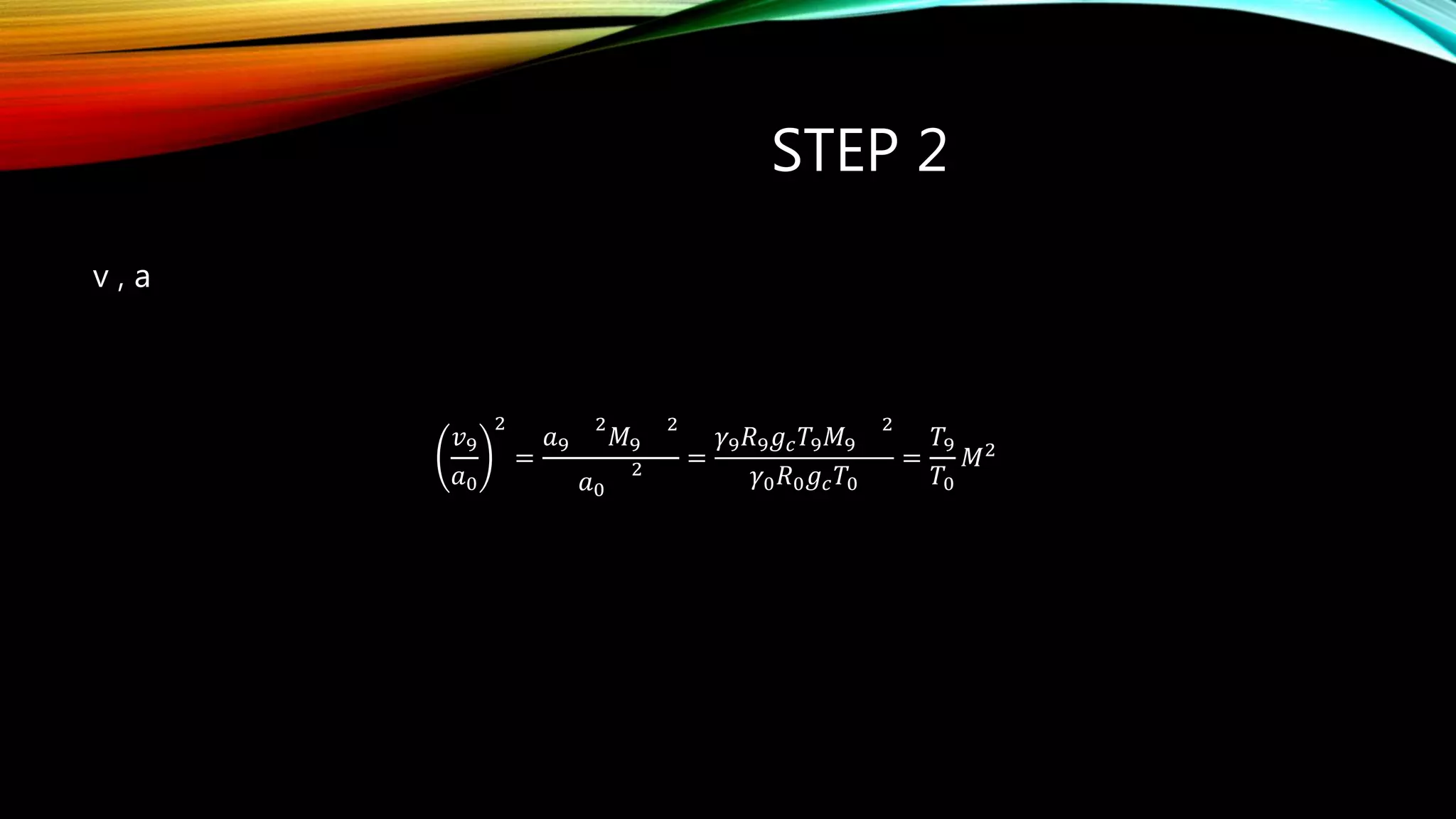
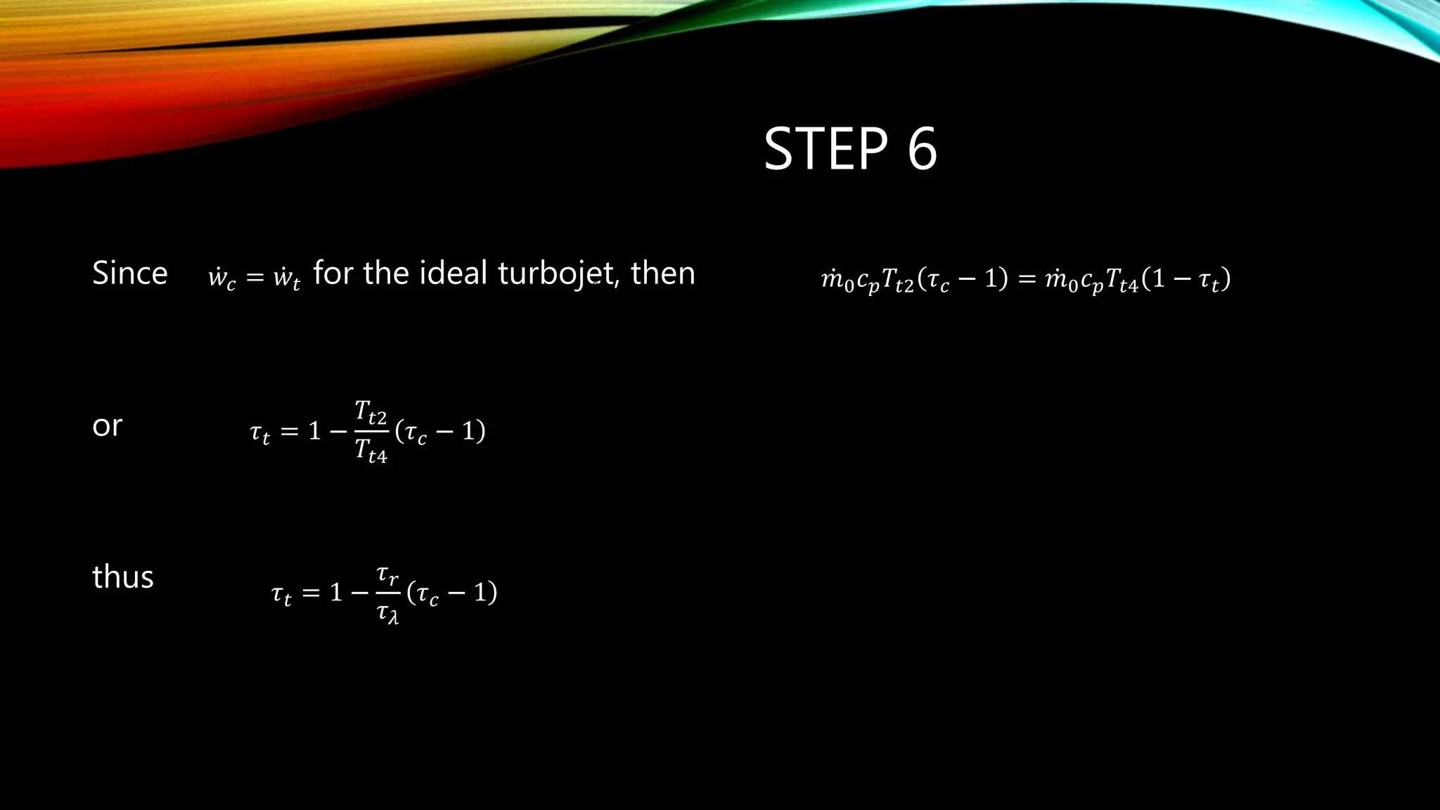
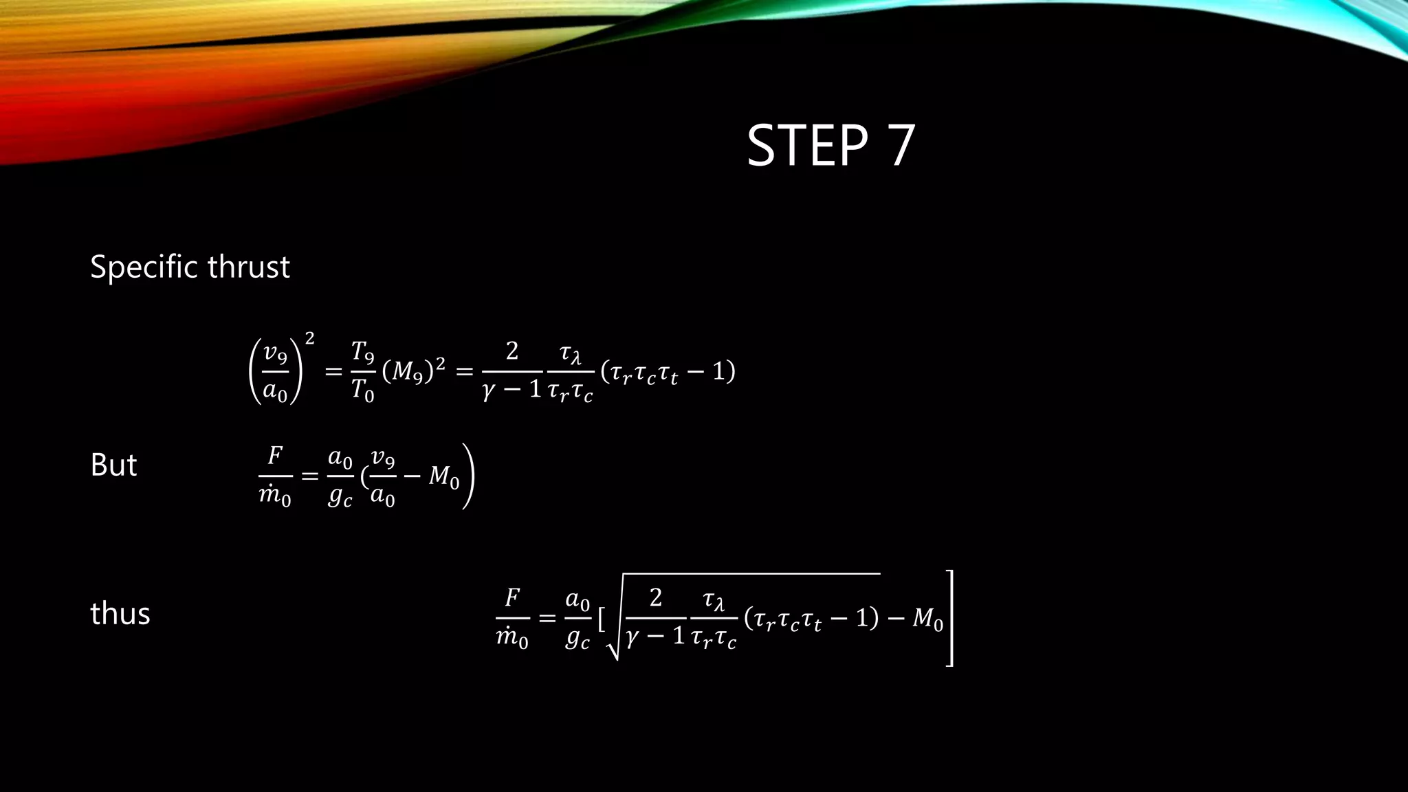
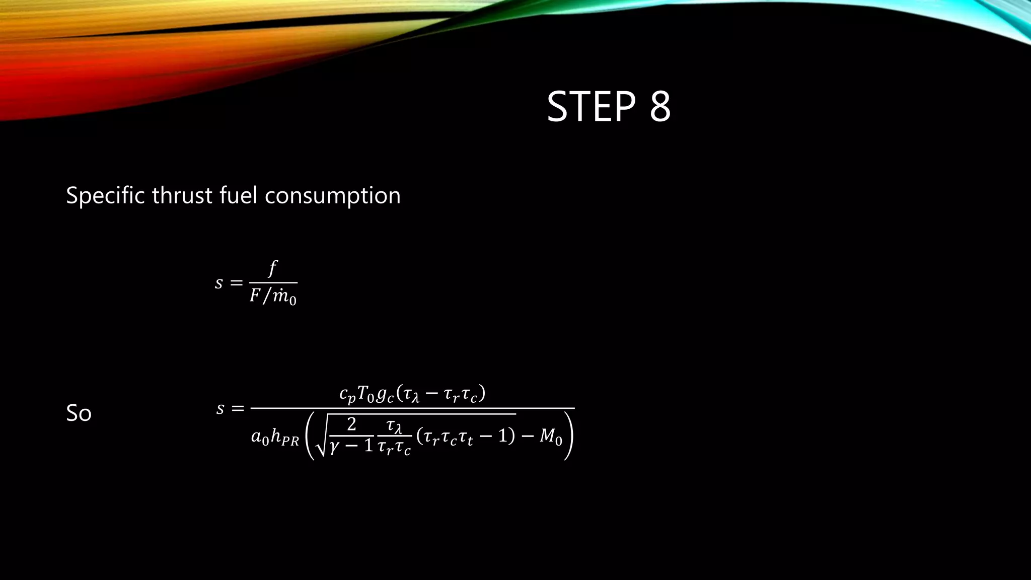
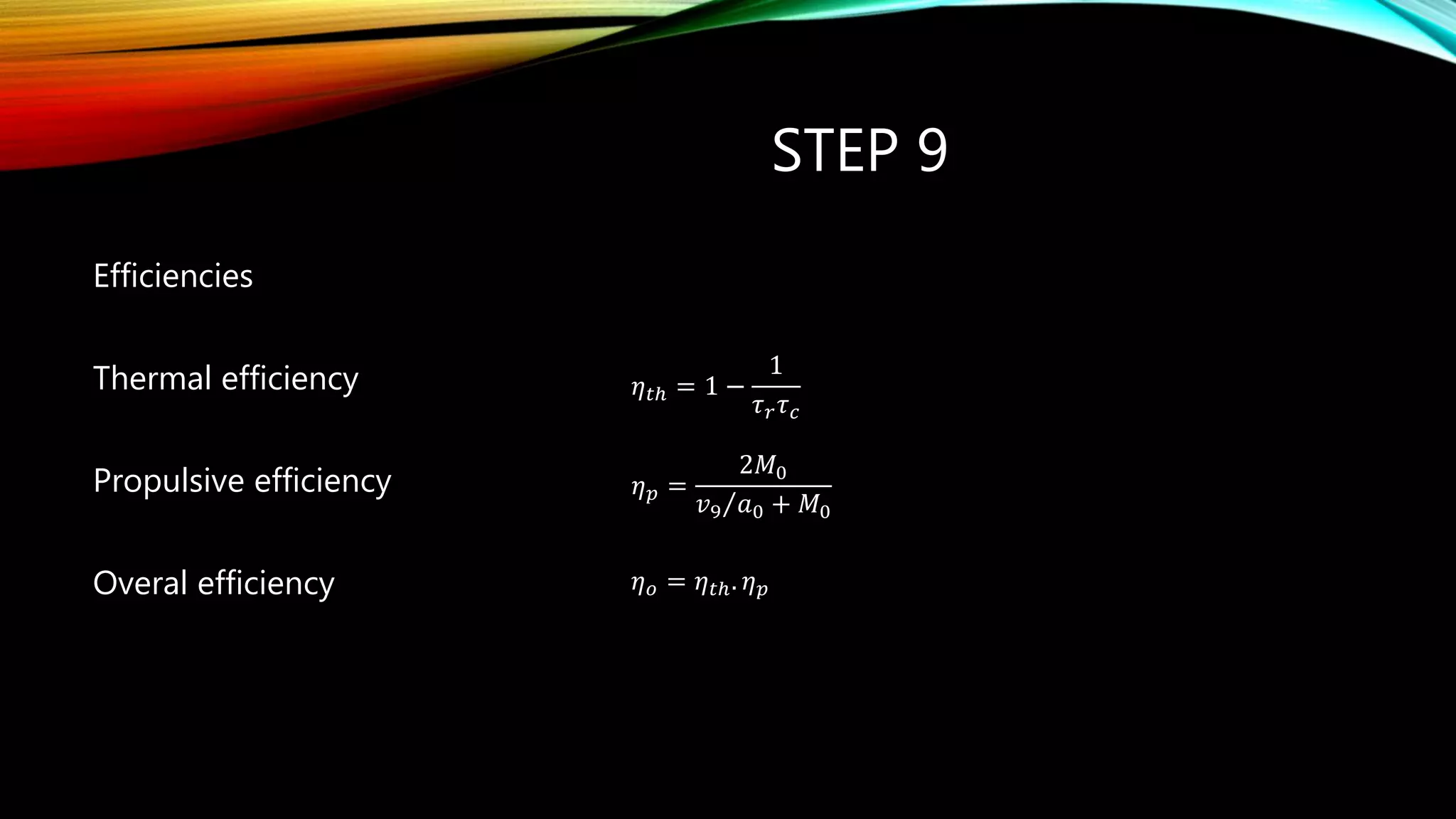
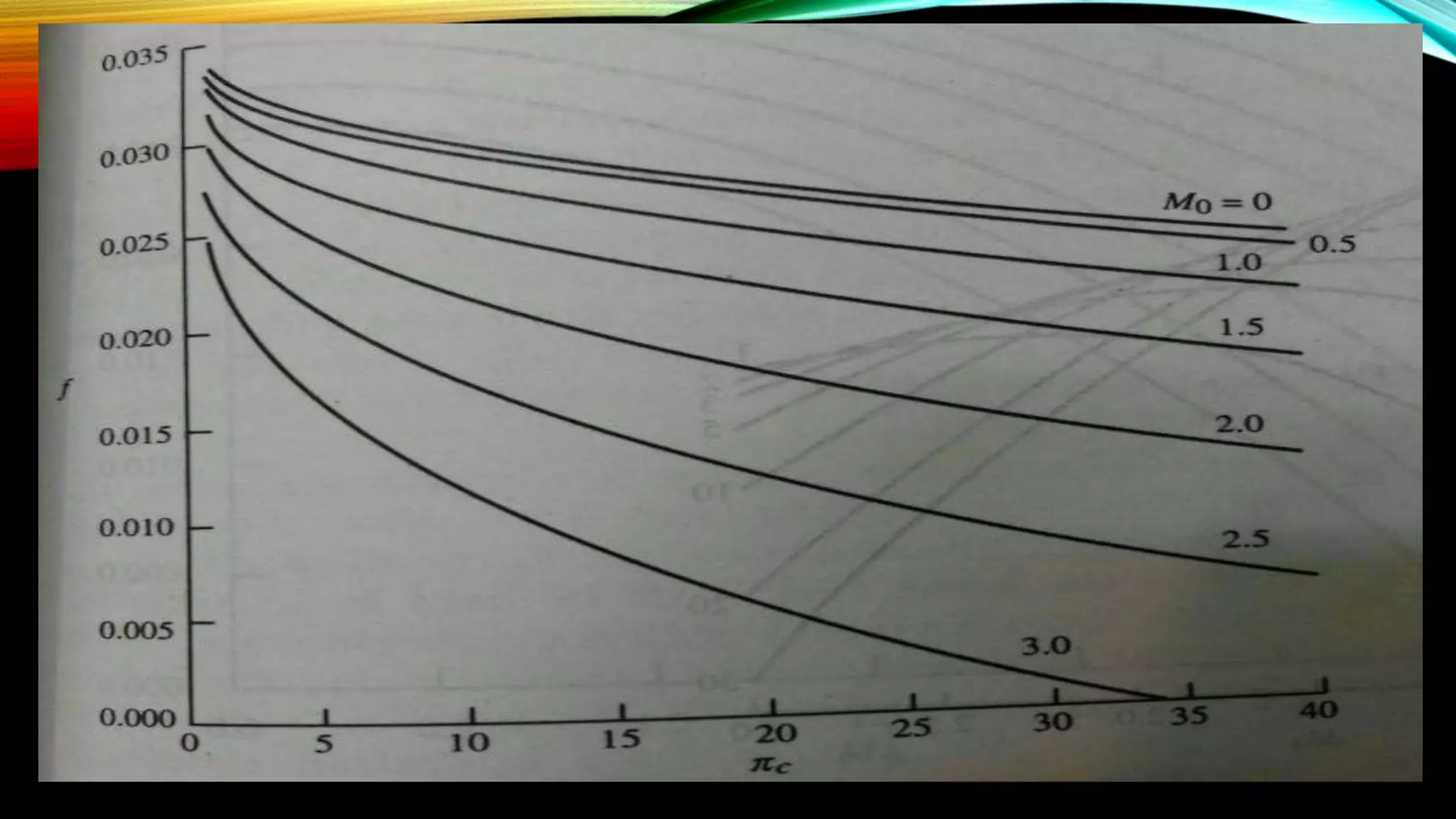
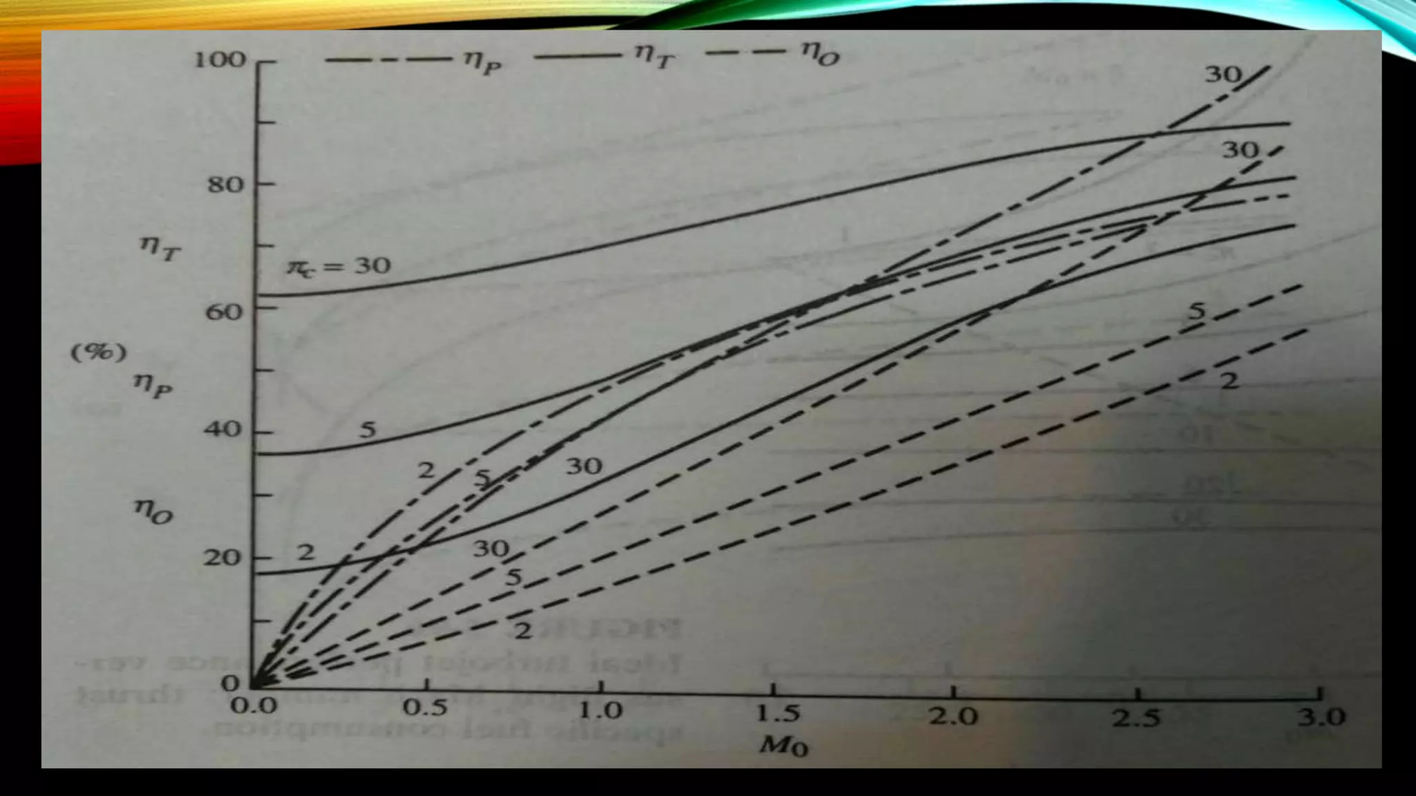
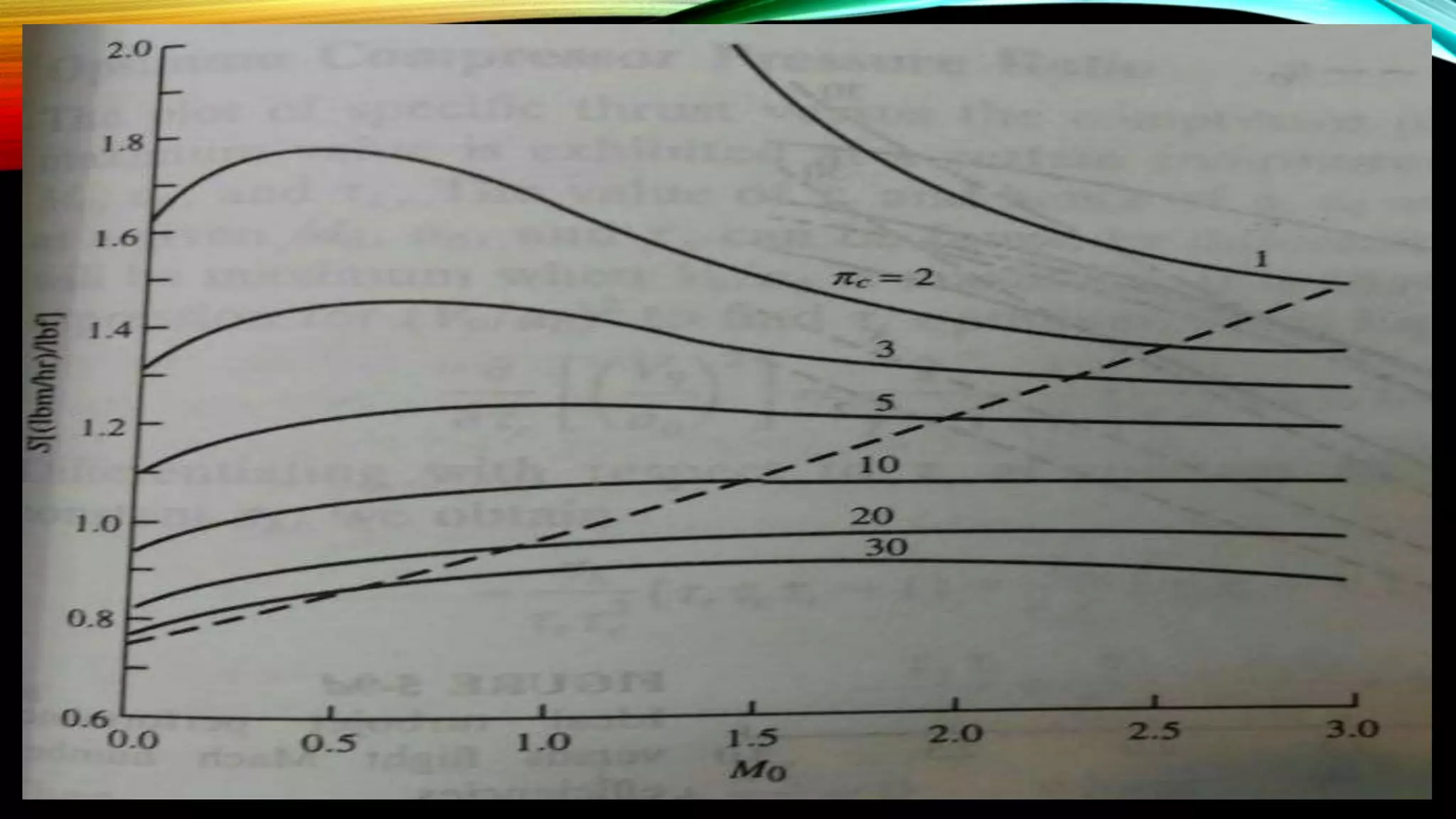
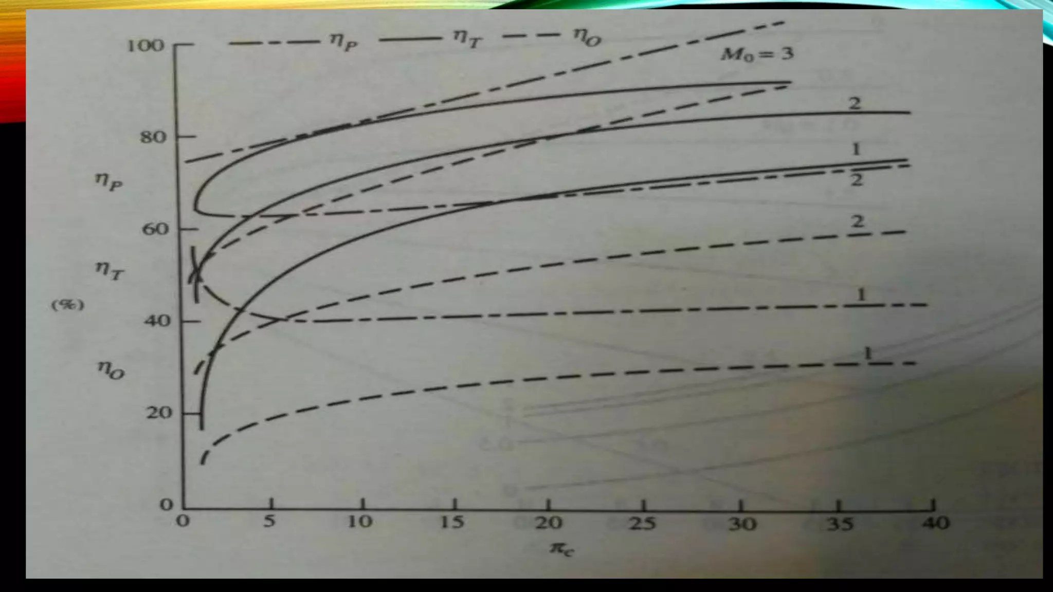
This document provides a summary of a presentation about turbomachines. It discusses the classification of turbomachines as either compressible or incompressible fluid machines that either transfer energy from or to a fluid using a rotating shaft. It also describes the components of turbomachines like compressors, turbines, bearings and systems used. The document discusses off-design and on-design analysis of turbomachines using the Euler turbine equation and the energy transfer between the rotor and fluid.
This document outlines the lecture topics for an internal combustion engine and turbomachinery course. It includes the class policies, a weekly lecture outline, and introductions to key concepts like the Otto cycle, diesel cycle, gas turbines, and turbomachinery terminology. The lecture outline covers topics such as thermodynamic cycles, engine classifications, component design, and performance prediction. Definitions and diagrams are provided for critical turbomachinery elements like stages, velocity diagrams, and flow configurations. Challenges like compressor stall and surge are also discussed.
Axial compressor theory - stage-by-stage approach - 28th January 2010CangTo Cheah
The document discusses the stage-by-stage sizing approach for axial compressors. This approach allows designers to calculate blade angles and estimate pressure rise, temperature rise, and frictional losses at each stage. It introduces concepts like the de Haller number to minimize losses. A case study on the RB211-24G engine axial compressors is presented, showing blade angles and performance across 7 low pressure and 6 high pressure stages.
The open gas-turbine cycle works as follows:
1. Air is compressed in a compressor, increasing its pressure and temperature.
2. The high-pressure air enters a combustion chamber where fuel is burned at constant pressure.
3. The high-temperature gas expands in a turbine, producing work and reducing to ambient pressure.
The Brayton cycle models the gas-turbine cycle with constant-pressure heat addition and rejection processes. Actual cycles have irreversibilities from non-isentropic compression/expansion and pressure drops. Efficiency can be improved with regeneration, intercooling, reheating, and multistage designs.
The document presents a preliminary design of a turbofan engine aimed at achieving over 25,000 N of thrust with a thrust specific fuel consumption of less than 0.025 kg/s/kN. A MATLAB code was used to generate carpet plots of specific thrust and thrust specific fuel consumption for different bypass ratios, compressor pressure ratios, and bypass pressure ratios. The final optimal design parameters chosen were: a turbine inlet temperature of 1300 K, compressor pressure ratio of 30, bypass ratio of 6, bypass pressure ratio of 1.35, inlet diameter of 0.738 m, thrust of 25,050.9 N, and thrust specific fuel consumption of 0.0187 in order to meet mission requirements with high fuel efficiency.
Predicting Performance Curves of Centrifugal Pumps in the Absence of OEM DataVijay Sarathy
Chemical and Mechanical Engineers in the oil & gas industry often carry out the task of conducting technical studies to evaluate piping and pipeline systems during events such as pump trips and block valve failures that can lead to pipes cracking at the welded joints, pump impellers rotating in the reverse direction and damaged pipe supports due to excessive vibrations to name a few. Although much literature is available to mitigate such disturbances, a key set of data to conduct transient studies are pump performance curves, a plot between pump head and flow.
The present paper is aimed at applying engineering research in industrial applications for practicing engineers. It provides a methodology called from available literature from past researchers, allowing engineers to predict performance curves for a Volute Casing End Suction Single Stage Radial Pump. In the current undertaking, the pump in question is not specific to any one industry but the principles are the same for a Volute Casing End suction radial pump.
FMP Fram Machinary And Power numericalsMehran Iqbal
This document contains 17 multi-part engineering questions regarding internal combustion engines. The questions cover topics such as: engine parameters including power, efficiency, airflow rates; air standard cycles; fuel-air cycles; carburetors; and fuel injection systems. Calculations are provided for power, pressures, temperatures, efficiencies, fuel flow rates, and more based on given engine specifications and operating conditions.
Thermodynamics of axial compressor and turbine - 3rd December 2009CangTo Cheah
This document discusses the thermodynamics of axial compressors and turbines used in gas turbines. It provides an overview of the Brayton cycle and discusses how to calculate the shaft power required for compression, temperature rises in the compressor, and outlet temperature as a function of pressure ratio, inlet temperature, and isentropic efficiency. Higher compression ratios are desirable because they increase turbine efficiency and overall gas turbine efficiency, though the rate of efficiency improvement decreases at higher ratios. Designing high-efficiency machines requires balancing increased efficiency from high compression against diminishing returns.
1. The document discusses constant volume combustion (CVC) in gas turbines, which offers higher theoretical efficiencies than traditional constant pressure combustion. CVC more closely approximates an ideal Carnot cycle.
2. Pulse detonation combustion holds promise as a way to achieve CVC in a steady-flow device. It involves intermittent combustion in tubes that results in pressure gains similar to CVC. General Electric and others have conducted research on pulse detonation combustion gas turbines.
3. Adopting CVC technologies could increase gas turbine efficiencies by 8-10 percentage points, allowing today's most efficient designs to be achieved at lower turbine inlet temperatures and with older materials. This could significantly reduce emissions.
MET 401 Chapter 6 -_gas_turbine_power_plant_brayton_cycle_-_copyIbrahim AboKhalil
This document discusses the Brayton cycle, which is the ideal gas turbine cycle. It covers:
1. The basic components and processes of the Brayton cycle, including constant pressure heat addition, isentropic expansion, and constant pressure heat rejection.
2. Key assumptions used in analyzing the cycle, such as treating air as an ideal gas and replacing combustion with heat addition.
3. Performance parameters like thermal efficiency as a function of pressure ratio and the impact of limiting turbine inlet temperatures.
4. Modifications to improve efficiency, including regeneration which recovers heat from the exhaust to preheat the compressor inlet air.
The document discusses various air standard cycles that are used to model internal combustion engine processes, including the Otto, Diesel, and dual cycles. It provides details on the assumptions and thermodynamic processes that define each cycle. The Otto cycle consists of four processes: constant-pressure intake, isentropic compression, constant-volume combustion, and isentropic expansion. The Diesel cycle models combustion as a constant-pressure process rather than constant volume. The dual cycle models combustion as both constant-volume and constant-pressure processes. Comparisons are made between the cycles in terms of their heat transfer and thermal efficiencies.
Use of Hydrogen in Fiat Lancia Petrol engine, Combustion Process and Determin...IOSR Journals
To our path towards green economy, Hydrogen is often regarded to have a potential growth in the
coming future. However, the high cost of operation of fuel cell has often been a setback. If we could make use of
hydrogen gas as a fuel directly, the scope of development broadens. Owing to these aspects, this work primarily
focuses on the simulation technique of an Internal Combustion Spark Ignition Engine powered by Hydrogen gas.
The simulations of various stages have been carried out using the discrete approach, thereby investigating the
pressures and temperatures at various instants in the cycle. For the relative performance discussion we have
simulated the different cycles as ideal cycle, air fuel cycle and actual cycle. The resultant cyclic graph indicates
various discrepancies between ideal, air fuel and actual cycle. This analysis serves as a tool for a better
understanding of the variables involved and helps in optimizing engine design and fixing of various parameters,
including the determination of valve timings. Besides this, backfire, is the commonly faced problem with the
hydrogen engines. To reduce this effect, a fuel injectoris used for adding the gaseous fuel to the combustion
chamber.
The document discusses different types of gas turbine cycles including direct open, indirect open, direct closed, and indirect closed cycles. It then focuses on the ideal Brayton cycle and how the net work output varies with pressure ratio, reaching a maximum at a specific pressure ratio. The regenerative Brayton cycle is introduced as an improvement where heat is recouped through a regenerator. Intercooling and reheating are also discussed as ways to further improve the cycle performance. Combined cycles, which use both gas and steam turbines, provide higher efficiencies than gas turbines alone. The ideal jet propulsion cycle for aircraft is described, where the turbine power is only used to drive the compressor.
The document provides the engineering problem definition, requirements, and analysis for designing a turbojet engine. It defines the operating conditions, constraints, and performance parameters to analyze. An engineering analysis is then presented using MATLAB code to calculate temperatures, pressures, mass flows, and other parameters across the engine for a range of compressor pressure ratios from 2 to 40. Graphs of key parameters like thrust, temperatures, mass flow, and efficiency are plotted to identify the highest performing compressor pressure ratio design.
This document presents the design of a nine-stage transonic axial compressor. It specifies the initial design parameters, including nine stages, a rotating speed of 9000 rpm, and ambient conditions. Calculations are shown to determine the blade angles, pressure and temperature ratios, mass flow rate, and shaft power for each stage. The results provide the inlet and outlet blade angles, pressure ratio per stage and overall, mass flow rate, and shaft power. The conclusion states that the key design values calculated include the blade angles, pressure ratios, and shaft power.
This document provides instructions for experiments on various turbomachines and pumps in the Mechanical Engineering Department of Aksum University. It includes procedures for determining the efficiency of a Pelton turbine, reaction turbine, axial turbine, and centrifugal pump. Formulas are provided for calculating mechanical power, hydraulic power, head, efficiency, and specific speed. Turbine tests involve varying the brake torque to obtain torque-speed characteristics while pumps are tested by varying the discharge.
The document discusses different types of compressors used to compress fluids. It classifies compressors into two main categories - rotodynamic compressors which include centrifugal and axial compressors, and positive displacement compressors which include reciprocating and rotary compressors. It then focuses on centrifugal compressors, describing their basic components like an impeller and diffuser, how they work to increase the pressure of air by accelerating it radially using an impeller before decelerating it in a diffuser, and factors affecting their gas dynamics.
here i have cover below topics
1. introduction
2. Components In Gas Turbine
3. Gas Turbine Working
4. Air Standard Cycle
5. Brayton Cycle
6. Brayton Cycle history
7. Gas Turbine Plant (Open Cycle)
8. Gas Turbine Plant (Close Cycle)
9. Brayton Cycle On P-V & T-S Plane
10. Efficiency of Brayton Cycle
11. Isentropic Efficiency Of Compressor
12. Isentropic Efficiency Of Turbine
13. Work Ratio
14. Merits and Demerits
This document provides information about a lecture on reheat and intercooling in gas turbine systems. It includes:
- An explanation of the concepts and purposes of using reheat and intercooling in gas turbines.
- An example problem calculating efficiency and mass flow rate for a gas turbine cycle with reheat and intercooling.
- Diagrams of gas turbine cycles with the different enhancements labeled.
This document discusses various criteria and comparisons of internal combustion engines, including:
1) Indicator power, brake power, friction power, thermal efficiency, specific fuel consumption, indicator mean effective pressure, torque, and volumetric efficiency are analyzed.
2) Graphs show relationships between torque and speed, brake power and indicated power vs speed, and mechanical efficiency vs speed and brake power.
3) Fuel consumption varies with engine speed, with laws enacted to require better vehicle fuel efficiency and decrease air pollution from depletion of fossil fuels.
The document discusses thermal power cycles and the Rankine cycle in particular. It provides details on:
- The basic energy flow in a thermal power plant from chemical to mechanical to electrical energy.
- The Rankine cycle most closely models the steam power cycle used in most power plants. It involves heating water to steam to drive a turbine and then condensing the steam to recycle the water.
- Ways to improve the efficiency of the Rankine cycle include increasing the average temperature of heat addition by superheating steam or increasing boiler pressure, and decreasing the average temperature of heat rejection by lowering the condenser pressure.
This document provides information about gas turbine and steam power plant cycles. It describes the Brayton cycle used in gas turbines and the Rankine cycle used in steam power plants. It discusses components, processes, thermal efficiencies and improvements to the cycles such as regeneration, intercooling and reheating. Examples are provided to calculate efficiency, work and heat inputs/outputs for simple and improved cycles.
1. The document discusses jet propulsion and compressor design, focusing on different types of turbines, compressors, and propulsion systems like propellers, rockets, turbojets, and scramjets.
2. It analyzes the advantages of propellers over rockets for aircraft propulsion in terms of efficiency and fuel requirements.
3. The importance of compressors and turbines in enabling modern high-speed flight is discussed, with examples given of how these technologies allowed the development of planes like the Blackbird that could reach supersonic speeds.
The document discusses reciprocating air compressors. It describes the basic components and working of single-stage and two-stage compressors. For two-stage compressors, it explains how intercooling between stages improves efficiency by reducing temperature and work input. Perfect intercooling approaches ideal isothermal compression by cooling the air to its initial temperature between stages.
Actual cycles for internal combustion engines differ from air-standard cycles in many respects.
Time loss factor.
Heat loss factor.
Exhaust blow down factor.
This document provides information on entropy and thermodynamics concepts including:
1. Entropy is a measure of irreversibilities and increases for all actual processes, being conserved only for idealized reversible processes.
2. Processes can only occur in the direction that complies with the increase of entropy principle.
3. Gas turbine cycles including Brayton, jet propulsion, and modifications like regeneration, intercooling and reheating are discussed. The efficiency and performance of these cycles depends on parameters like pressure and temperature ratios.
This document discusses steam nozzles and turbines. It begins by explaining how steam nozzles convert heat energy of steam into kinetic energy in two stages. It then describes the types of steam nozzles, including convergent, divergent, and convergent-divergent nozzles. The document also covers steam turbines, including their classification into impulse and reaction turbines. It provides details on velocity diagrams and analyzing impulse and reaction turbines, including the velocity variations of steam as it passes through turbine blades.
The document provides information about steam turbines, including:
1) It describes different types of steam nozzles and how they convert heat energy of steam into kinetic energy.
2) It discusses classifications of steam turbines as impulse turbines and reaction turbines and how they expand steam.
3) It explains concepts like compounding, velocity diagrams, and how to analyze impulse and reaction turbines to calculate work done and power output.
Generally Pumps classification done on the basis of its mechanical configurat...ShriPrakash33
Pumps simplify the transportation of water and other fluids, making them very useful in all types of buildings - residential, commercial, and industrial. For example, fire pumps provide a pressurized water supply for firefighters and automatic sprinklers, water booster pumps deliver potable water to upper floors in tall buildings, and hydronic pumps are used in HVAC systems that use water to deliver space heating and cooling.
TYPES OF PUMPS AND THEIR WORKING PRINCIPLES
Generally Pumps classification done on the basis of its mechanical configuration and their working principle. Classification of pumps mainly divided into two major categories:
Dynamic pumps / Kinetic pumps
Dynamic pumps impart velocity and pressure to the fluid as it moves past or through the pump impeller and, subsequently, convert some of that velocity into additional pressure. It is also called Kinetic pumps Kinetic pumps are subdivided into two major groups and they are centrifugal pumps and positive displacement pumps.
Classification of Dynamic Pumps
1.1 Centrifugal Pumps
A centrifugal pump is a rotating machine in which flow and pressure are generated dynamically. The energy changes occur by virtue of two main parts of the pump, the impeller and the volute or casing. The function of the casing is to collect the liquid discharged by the impeller and to convert some of the kinetic (velocity) energy into pressure energy.
1.2 Vertical Pumps
Vertical pumps were originally developed for well pumping. The bore size of the well limits the outside diameter of the pump and so controls the overall pump design.2.) Displacement Pumps / Positive displacement pumps
2. Displacement Pumps / Positive displacement pumps
Positive displacement pumps, the moving element (piston, plunger, rotor, lobe, or gear) displaces the liquid from the pump casing (or cylinder) and, at the same time, raises the pressure of the liquid. So displacement pump does not develop pressure; it only produces a flow of fluid.
Classification of Displacement Pumps
2.1 Reciprocating pumps
In a reciprocating pump, a piston or plunger moves up and down. During the suction stroke, the pump cylinder fills with fresh liquid, and the discharge stroke displaces it through a check valve into the discharge line. Reciprocating pumps can develop very high pressures. Plunger, piston and diaphragm pumps are under these type of pumps.
2.2 Rotary Type Pumps
The pump rotor of rotary pumps displaces the liquid either by rotating or by a rotating and orbiting motion. The rotary pump mechanisms consisting of a casing with closely fitted cams, lobes, or vanes, that provide a means for conveying a fluid. Vane, gear, and lobe pumps are positive displacement rotary pumps.
2.3 Pneumatic Pumps
Compressed air is used to move the liquid in pneumatic pumps. In pneumatic ejectors, compressed air displaces the liquid from a gravity-fed pressure vessel through a check valve into the discharge line in a series of surges spaced by the time required.
OPTIMIZATION OF AN ORGANIC RANKINE CYCLE IN ENERGY RECOVERY FROM EXHAUST GASE...IAEME Publication
This paper describes thermal analysis and optimization of an organic Rankine cycle (ORC) integrated with a power generating stationary diesel engine. A simple ORC, with a regenerator, is considered here as a bottoming cycle for producing additional power by recovering waste energy
from the exhaust gases of the engine. Taking evaporation pressure and condensation temperature as two decision variables, a genetic algorithm is used for simultaneously maximizing three objective functions - exergy efficiency, thermal efficiency, and specific network.
The document discusses gas turbine cycles and thermodynamic cycles used in gas turbines. It begins by describing air standard cycles and assumptions made, including the working fluid behaving as an ideal gas. It then discusses the Otto cycle which models spark ignition engines and the processes involved. Details of the Otto cycle calculation are provided. The document also discusses the diesel cycle which models compression ignition engines and provides cycle calculations. Other topics covered include mean effective pressure, engine terminology, gas turbine components and cycles like the Brayton cycle.
This document discusses fan concept and analysis in the cement industry. It provides information on static pressure, system resistance, gas properties, density correction factors, barometric pressure, and pitot tube measurements. It also discusses fan classifications, differences between fans and blowers/compressors, major process fans, system curves, fan laws, factors affecting fan performance, and calculations for fan efficiency, head, power savings, and damper losses. Case studies are presented on ESP exhaust fan retrofitting opportunities to increase efficiency.
This report gives basic knowledge about overhauling of Turbine, erection, commissioning.
For more information visit@supratheek Turbo Engineering Services
This document provides an overview of propulsion systems. It discusses different types of propulsion including liquid, solid, electric propulsion and others. It also covers key concepts in propulsion performance including specific impulse, thrust, nozzle design and equations. The document uses examples and diagrams to illustrate concepts in propulsion systems and their applications in launch vehicles and spacecraft.
This document discusses various thermodynamic cycles used in power generation applications including vapor power cycles, gas power cycles, and gas turbine cycles. It describes the basic processes and assumptions of cycles like the Rankine, Otto, diesel, and Brayton cycles. Methods to improve the performance of these cycles are also covered, such as increasing boiler pressure, superheating, reheating, and regeneration. The key applications of thermodynamics discussed are steam power plants, internal combustion engines, and gas turbine engines.
This document summarizes the key differences between open cycle and closed cycle gas turbines. It explains that open cycle gas turbines involve irreversible compression and expansion processes, while closed cycle gas turbines involve ideal isentropic compression and expansion. The document also discusses gas turbine cycles with intercooling and reheat to increase output, as well as regenerative cycles to improve efficiency. Additional sections cover the advantages of gas turbines over internal combustion engines and steam turbines.
This document provides an overview of micro gas turbines. It discusses that micro turbines are small combustion turbines that can generate 25-500 kW of power. They have high power-to-weight ratios and reliability compared to reciprocating engines. Micro turbines are used in distributed generation applications and can utilize various fuels to provide both power and heat in a combined heat and power system. They have potential applications in India to help address power shortages by generating electricity on-site using fuels like biogas.
This document summarizes a student internship project on gas turbine performance simulation undertaken at Cranfield University. The project involved using Turbomatch software to simulate the off-design performance of 3 turbofan engines - CFM56-7B27, Rolls Royce Trent 1000, and Pratt & Whitney 4084. The student analyzed compressor maps, plotted performance parameters like thrust and SFC against turbine inlet temperature and ambient temperature, and compared results between 2 versions of Turbomatch software. The analysis provided insights into engine operation and limitations as well as improvements in the new Turbomatch version.
The document describes the workings of a gas turbine engine. It begins by explaining the basic components and processes of a gas turbine, including the compressor, combustion chamber, and turbine. It then discusses different classifications of gas turbines based on combustion type. Next, it lists some merits of gas turbines over internal combustion engines, as well as some demerits. The document proceeds to outline common assumptions made in analyzing ideal gas turbine cycles. It provides an in-depth explanation of the Brayton cycle as the basic cycle for gas turbines. Finally, it discusses various methods for improving gas turbine efficiency, such as increasing combustion temperatures, improving machine efficiencies, and modifying the basic cycle through regeneration and reheat.
APPLIED THERMODYNAMICS 18ME42 Module 03: Vapour Power CyclesTHANMAY JS
This document provides an overview of vapor power cycles, including the Carnot and Rankine cycles. It describes:
1) The Carnot vapor power cycle, including its four reversible processes of isothermal heat addition and rejection and adiabatic expansion and compression. However, it notes that the Carnot cycle is difficult to implement in practice.
2) The simple Rankine cycle, which uses the same four processes as the Carnot cycle but with complete condensation in the condenser. Equations for thermal efficiency are provided.
3) Key parameters used to analyze vapor power cycle performance such as heat added, heat rejected, turbine work, and pumping work.
This so called PPT for propulsion study for Shenyang Aerospace University. This PPT right protected by Dr. divinder K. Yadav. Its using in SAU by Lale. For all students of Aeronautical Engineering must memorize each & every words from this PPT. If you miss a single words you must fail in the Exam. Remember there is no chance to be creative or use sense you just need to use the power of memorizing.
The document discusses gas turbine technology. It begins by defining a gas turbine as a machine that delivers mechanical power using a gaseous working fluid. It then discusses the main components of a gas turbine - the compressor, combustion chamber, and turbine. The document covers various gas turbine cycles including open and closed cycles. It also discusses ways to improve gas turbine efficiency such as intercooling, reheating, and regeneration. The document provides an overview of gas turbine applications and operating principles.
1. The document discusses gas turbine power plants, including their working principles, components, types (open vs closed cycle), and methods to improve efficiency like intercooling, reheating, and regeneration.
2. It also covers the ideal Brayton cycle that gas turbines undergo and compares the characteristics of open and closed cycle plants.
3. Combinations of gas turbines with steam and diesel power plants are described to further improve overall efficiency.
This document describes a project to optimize the performance of a steam turbine power plant using the Rankine cycle. Five different Rankine cycles are analyzed: 1) the ideal Rankine cycle, 2) the ideal Rankine cycle with reheat, 3) the ideal Rankine cycle with one open feedwater heater, 4) with two open feedwater heaters, and 5) with four open feedwater heaters. Sample calculations are shown for each cycle configuration to determine the thermal efficiency. The document also discusses cost effectiveness calculations to determine the most optimal design for the steam turbine.
2. A BRIEF SEMINAR PRESENTATION ABOUT
TURBOMACHINES
• 2nd project for thermodynomics
• Presented by Shahin Tavakoli and Hasan Parvin
3. OVERLOOK
• Introduction – categorization – classiffication
• Types of turbomachines and the components
• Systems using in turbomachines
• Off-design (power transfer equation)
• On-design (ideal turbomachine analysis)
7. PUT TURBOMACHINES TOGETHER TO CREAT
“THRUST”
Propulsive turbomachines
Air breathing
Turbine powered
Ram powered
Non-continuous combustion
Non-air breathing
rocket
hybrid
waterjet
15. COMPRESSORS
• Pressure ratio 5-1 world war 2
12-1 newer
30-1 recently
Better pressure ratio better thermal efficiiency
The best thermal efficiency is about 35 %
To achieve this thermal efficiency we should use some forms of “waste heat recovery”
Special material (Al , Fe and their alloys)
16. TURBINES
Turbofan high aspect ratio (long , thin blades) with tip shrouds
1.to dampen vibration
2.improve blade tip sealing characteristics
Turboshaft low aspect ratio (short , thick blades)
with no tip shrouds
Long thin airfoils need 1.lacing wire to dampen vibration
2.tip shrouds or mid-spam shrouds
25. POLLUTION
*carbon mono-oxide(co) 1.function of combustion design
2.can be treated with a catalytic converter
*oxides of nitrogen(NOx) 1. (organic NO)
2.produced in hot regions (thermal NO)
ℎ𝑦𝑑𝑟𝑜𝑐𝑎𝑟𝑏𝑜𝑛. 𝑓𝑢𝑒𝑙 + 𝑎𝑖𝑟 →. . . . . . . +𝑁𝑂𝑥
28. THRUST (POWER) AUGMENTATION
• First way : cooling air entering combustor
a) Increasing air density
b) Increasing mass flow
c) More air and more cooled air to the combustor permits more fuel to be burned
before reaching the turbine inlet temperaturre limit
To cooling the air enterring combustor, water or steam injection is ok
29. WATER INJECTION
into diffuser, compressor or combustor
reducing combustion and turbine temperature
reducing oxides of nitrogen up to 80 %
Example in a heavy industrial gas turbine with 80 MW power output
ratio of water to fuel is 0.6
water is 1.15 % of total air intaking
31. STEAM INJECTION
energy to vaporizing the water is conserved
reducing combustion and turbine temperature
steam is hot so it’s quenching capabilities are reduced
so more steam than the water is required to accomplish the same
amounts of nitrogen oxides
Example in an airo-drivative gas turbine with 25 MW power outpuut
ratio of steam to fuel is up to 2.4
steam is 3.3 % of total air
34. AFTER BURNING OR REHEATING
Effect of after burner raising the exhaust temperature
raising the velocity of exhaust gases
Example with afterburner thrust = 17,900 lbf
TSFC = 1.956 ((lbm/hr)/lbf)/hr
without afterburner thrust = 11,870 lbf
TSFC = 0.86((lbm/hr)/lbf)/hr
56. STEP 5
• 5. apply the 1st law of thermodynamics to the burner and find an expression for the
fuel/air ratio
0 3 0 4p t f PR p tm c T m h m c T & & &
𝑚0 𝑐 𝑝 𝑇𝑡3 + 𝑚 𝑓ℎ 𝑃𝑅 = 𝑚0 𝑐 𝑝 𝑇𝑡4
57. STEP 6,7
• 6. when applicable, find an expression for the total temperature ratio across the
turbine by relating the turbine power output to the compressor, fan, and/or
propeller power requirements. This allows us to find in terms of other variables.
• 7. evaluate the specific thrust using the above results
t
𝜏 𝑡
𝜏 𝑡
58. STEP 8,9
• 8. evaluate the thrust specific fuel consumption , using the results for specific
thrust and fuel/air ratio
• 9. develop expressions for the thermal and propulsive efficiencies
1
1
d n
d n
𝑠
𝑠 =
𝑓
𝐹 𝑚0
59. ASSUMPTIONS
OF IDEAL CYCLE ANALYSIS
• 1.the working fluid is air and acts as a perfect gas
• 2.isentropic ( reversible and adiabatic ) processes
𝜏 𝑑 = 𝜏 𝑛 = 1 𝜋 𝑑 = 𝜋 𝑛 = 1
𝜏 𝑐 = 𝜋 𝑐
𝛾−1
𝛾 𝜏 𝑡 = 𝜋 𝑡
𝛾−1
𝛾
60. ASSUMPTIONS
OF IDEAL CYCLE ANALYSIS
• 3.the exhaust nozzle expand the gas to the ambient pressure
• 4.constant pressure combustion
; ;
𝑝 𝑒 = 𝑝0
𝜋 𝑏 = 1
𝑚 𝑓 <<< 𝑚 𝑎𝑖𝑟
𝑚 𝑓
𝑚 𝑐
<< 1 𝑚 𝑐 + 𝑚 𝑓 ≅ 𝑚 𝑐