This document provides product data for Grundfos' CH and CHN range of horizontal multistage centrifugal pumps. It includes:
- Applications and performance ranges for pumping thin, clean liquids for water supply and industrial uses
- Specifications for pump components, materials, motor, and operating conditions
- Dimensional drawings and performance curves showing flow rate, head pressure, and energy efficiency for various pump sizes
- Electrical data and physical dimensions for pump selection

![3
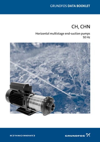
CH, CHNProduct data
Applications
The CH, CHN range of compact, horizontal, centrifugal
pumps is designed for small domestic and industrial water
supply systems.
Applications include:
• Liquid transfer:
Transfer and circulation of liquids within light indus-
try and farming.
• Pressure boosting:
Built into single-pump and multi-pump booster
systems.
• Domestic water supply.
• Cooling systems.
• Air-conditioning systems.
In addition to this, the CH, CHN range is suitable for incor-
poration in specialized OEM equipment.
(OEM = Original Equipment Manufacturer).
Type key
Performance range
Example CH 4- 30 (x) A- A- CVBV
Pump type
Blank = Standard version
N = All components in contact with
the pumped liquid are of stainless
steel EN/DIN 1.4301 and cast
stainless steel EN/DIN 1.4308
Nominal flow rate [m3/h]
Max. discharge pressure [m]
Code for special product
Code for physical dimensions
Code for materials
Code for shaft seal
TM0212393603
1 2 3 4 5 6 7 8 9 10 11 12 13 Q [m³/h]
0
5
10
15
20
25
30
35
40
45
50
55
H
[m]
0.5 1.0 1.5 2.0 2.5 3.0 3.5 Q [l/s]
0
100
200
300
400
500
p
[kPa]
CH, CHN
50 Hz
ISO 9906 Annex A
CH 12CH 8CH 4CH 2
CHN 2 CHN 4](https://image.slidesharecdn.com/ch-chn-151010053306-lva1-app6891/85/Ch-chn-3-320.jpg)
![6
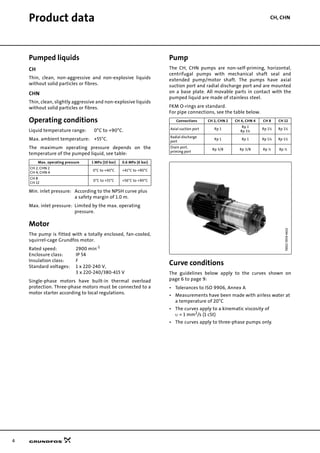
CH 2, CHN 2Performance curves
Electrical data, 2900 min-1
TM0203803302Performancecurves,electricaldataCH2,CHN2
0.0 0.4 0.8 1.2 1.6 2.0 2.4 2.8 3.2 Q [m³/h]
0
5
10
15
20
25
30
35
40
45
50
55
H
[m]
0.0 0.2 0.4 0.6 0.8 1.0 Q [l/s]
0
100
200
300
400
500
p
[kPa]
CH 2, CHN 2
50 Hz
ISO 9906 Annex A
CH(N) 2-20
CH(N) 2-30
CH(N) 2-40
CH(N) 2-50
CH(N) 2-60
0.0 0.4 0.8 1.2 1.6 2.0 2.4 2.8 3.2 Q [m³/h]
0.0
0.2
0.4
0.6
0.8
P1
[kW]
-20
-30
-40
-50
-60
0.0 0.4 0.8 1.2 1.6 2.0 2.4 2.8 3.2 Q [m³/h]
0
2
4
6
NPSH
[m]
0
20
40
60
p
[kPa]
0
10
20
30
[%]
Eta
Eta 1
NPSH
Pump type
P1 [W] I1/1 [A]
1 x 220-240 V 3 x 220-240/380-415 V 1 x 220-240 V 3 x 220-240/380-415 V
CH 2-20, CHN 2-20 420 350 2.2 1.6 / 0.9
CH 2-30, CHN 2-30 480 420 2.3 1.7 / 1.0
CH 2-40, CHN 2-40 570 520 2.6 1.9 / 1.1
CH 2-50, CHN 2-50 680 675 2.9 2.1/ 1.2
CH 2-60, CHN 2-60 800 780 3.7 2.3 / 1.4](https://image.slidesharecdn.com/ch-chn-151010053306-lva1-app6891/85/Ch-chn-6-320.jpg)
![7
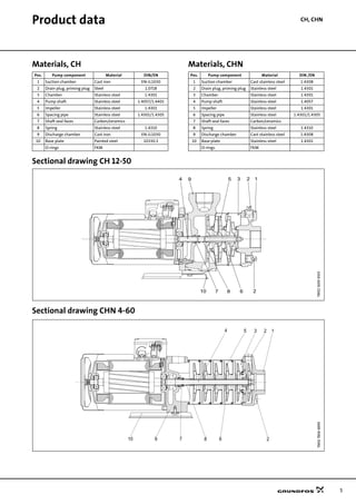
Performance curves CH 4, CHN 4
Electrical data, 2900 min-1
TM0203903302CH4,CHN4
0 1 2 3 4 5 6 7 8 Q [m³/h]
0
5
10
15
20
25
30
35
40
45
50
H
[m]
0.0 0.4 0.8 1.2 1.6 2.0 Q [l/s]
0
100
200
300
400
500
p
[kPa]
CH 4, CHN 4
50 Hz
ISO 9906 Annex A
CH(N) 4-20
CH(N) 4-30
CH(N) 4-40
CH(N) 4-50
CH(N)4-60
0 1 2 3 4 5 6 7 8 Q [m³/h]
0.0
0.4
0.8
1.2
P1
[kW] -60
-50
-40
-30
-20
0 1 2 3 4 5 6 7 8 Q [m³/h]
0
1
2
3
NPSH
[m]
0
10
20
30
p
[kPa]
0
10
20
30
[%]
Eta
Eta 1
NPSH
Pump type
P1 [W] I1/1 [A]
1 x 220-240 V 3 x 220-240/380-415 V 1 x 220-240 V 3 x 220-240/380-415 V
CH 4-20, CHN 4-20 540 520 2.4 1.9 / 1.1
CH 4-30, CHN 4-30 840 635 4.1 2.1 / 1.2
CH 4-40, CHN 4-40 1160 910 5.5 2.8 / 1.6
CH 4-50, CHN 4-50 1300 1300 6.0 4.0 / 2.3
CH 4-60, CHN 4-60 1460 1490 7.0 4.4 / 2.5](https://image.slidesharecdn.com/ch-chn-151010053306-lva1-app6891/85/Ch-chn-7-320.jpg)
![8
Performance curves CH 8
Electrical data, 2900 min-1
TM0203983603
0 1 2 3 4 5 6 7 8 9 Q [m³/h]
0
5
10
15
20
25
30
35
40
45
50
55
60
H
[m]
0.0 0.4 0.8 1.2 1.6 2.0 2.4 2.8Q [l/s]
0
100
200
300
400
500
600
p
[kPa]
CH 8
50 Hz
ISO 9906 Annex A
CH 8-50
CH 8-60
CH 8-20
CH 8-30
CH 8-40
0 1 2 3 4 5 6 7 8 9 Q [m³/h]
0.0
0.5
1.0
1.5
2.0
P1
[kW]
-60
-50
-40
-30
-20
0 1 2 3 4 5 6 7 8 9 Q [m³/h]
0
1
2
3
4
NPSH
[m]
0
10
20
30
40
p
[kPa]
0
10
20
30
40
[%]
Eta
Eta 1
NPSH
Pump type
P1 [W] I1/1 [A]
1 x 220-240 V 3 x 220-240/380-415 V 1 x 220-240 V 3 x 220-240/380-415 V
CH 8-20 730 650 3.2 2.1 / 1.2
CH 8-30 970 1030 4.3 3.4 /2.0
CH 8-40 1330 1290 5.6 4.7 / 2.7
CH 8-50 1740 1650 7.8 5.2 / 3.0
CH 8-60 1930 1930 8.5 5.9 / 3.4](https://image.slidesharecdn.com/ch-chn-151010053306-lva1-app6891/85/Ch-chn-8-320.jpg)
![9
Performance curves CH 12
Electrical data, 2900 min-1
TM0204064400
0 2 4 6 8 10 12 14 Q [m³/h]
0
5
10
15
20
25
30
35
40
45
50
55
60
H
[m]
0 1 2 3 4 Q [l/s]
0
100
200
300
400
500
600
p
[kPa]
CH 12
50 Hz
ISO 9906 Annex A
CH 12-20
CH 12-30
CH 12-40
CH 12-50
CH 12-60
0 2 4 6 8 10 12 14 Q [m³/h]
0
1
2
3
P1
[kW]
-20
-30
-40
-50
-60
0 2 4 6 8 10 12 14 Q [m³/h]
0
1
2
3
4
5
NPSH
[m]
0
10
20
30
40
p
[kPa]
0
10
20
30
40
50
[%]
Eta
Eta 1
NPSH
Pump type
P1 [W] I1/1 [A]
1 x 220-240 V 3 x 220-240/380-415 V 1 x 220-240 V 3 x 220-240/380-415 V
CH 12-20 1060 1030 4.8 3.2 / 1.8
CH 12-30 1520 1530 6.8 4.3 / 2.5
CH 12-40 2180 2200 9.6 6.6 / 3.8
CH 12-50 2560 2690 11.3 8.1 / 4.8
CH 12-60 - 3180 - 9.4 / 5.5](https://image.slidesharecdn.com/ch-chn-151010053306-lva1-app6891/85/Ch-chn-9-320.jpg)
![10
Technical data CH, CHN
Dimensions and weights CH 2, CHN 2 and CH 4, CHN 4
CH 8 and CH 12
TM0014913702Dimensionsandweights
Rp 1
CH 4 Rp 1 + Rp 1 1/4
CH 2 Rp 1 Rp 3/8
Rp 3/8
L4
H
L1
160L3
138L2
ø8.5
90
155
130
108
B2
B1
Pump type
Motor type
L1
[mm] L2
[mm]
L3
[mm]
L4
[mm]
B1
[mm]
B2
[mm]
H
[mm]
Net weight
[kg]
1-phase 3-phase 1-phase 3-phase 1-phase 3-phase 1-phase 3-phase 1-phase 3-phase
CH, CHN 2-20
MG 71 MG 71
304 304 74 63 99 146 115 110 205 200 9.6 11.1
CH, CHN 2-30 324 322 92 81 117 146 115 110 205 200 9.6 10.7
CH, CHN 2-40 340 340 110 99 135 146 115 110 205 200 10.9 11.0
CH, CHN 2-50 358 358 128 117 154 146 115 110 205 200 11.3 11.5
CH, CHN 2-60 376 376 146 135 172 146 115 110 205 200 11.6 11.8
CH, CHN 4-20 314 314 83 72 108 146 115 115 205 200 9.5 9.6
CH, CHN 4-30 342 342 110 99 135 146 110 110 205 200 10.9 11.0
CH, CHN 4-40 370 370 137 126 163 146 110 110 205 200 12.3 12.5
CH, CHN 4-50
MG 80 MG 80
436 438 164 153 190 142 135 110 225 200 16.0 14.2
CH, CHN 4-60 466 466 191 180 217 142 135 110 225 200 15.2 14.9
TM0011894503
Rp 1/2
Rp 1/2
Rp 1 1/2
CH 12 Rp 1 1/2
CH 8 Rp 1 1/4
L4
240
ø8.5
L1
L3
L2
160
138
110
188
130
108
B2
B1
Pump type
Motor type
L1
[mm] L2
[mm]
L3
[mm]
L4
[mm]
B1 [mm] B2 [mm] Net weight [kg]
1-phase 3-phase 1-phase 3-phase 1-phase 3-phase 1-phase 3-phase 1-phase 3-phase
CH 8-20 MG 71 MG 71 311 311 69 58 77 177 177 109 109 15.0 15.0
CH 8-30
MG 80
MG 80
381 381 99 88 107 177 177 109 109 17.0 17.0
CH 8-40 381 381 99 88 107 177 177 109 109 19.0 19.0
CH 8-50
MG 90
459 411 129 118 137 182 177 - 109 28.8 20.0
CH 8-60 MG 90 459 459 129 118 137 182 182 - - 28.8 25.0
CH 12-20
MG 80 MG 80
351 351 69 58 77 177 177 109 109 17.0 17.0
CH 12-30 381 381 99 88 107 177 177 109 109 19.0 19.0
CH 12-40
MG 90
MG 90
429 429 99 88 107 182 182 - - 26.0 24.0
CH 12-50 459 459 129 118 137 182 182 - - 27.0 27.0
CH 12-60 - - 459 129 118 137 - 182 - - - 27.0](https://image.slidesharecdn.com/ch-chn-151010053306-lva1-app6891/85/Ch-chn-10-320.jpg)


