Download to read offline

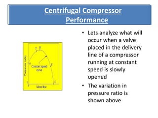
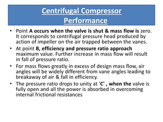
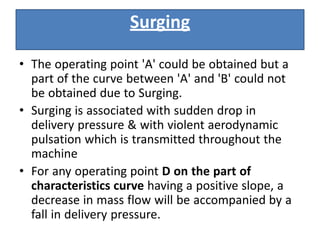
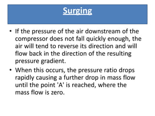


The document discusses the performance characteristics and losses of centrifugal compressors, focusing on the effects of valve operation on pressure ratios and efficiency. It explains phenomena such as surging and choking, detailing how these issues arise from variations in mass flow and pressure conditions. Additionally, it outlines different types of losses in compressors, including frictional, incidence, and clearance losses, along with their impact on efficiency.


