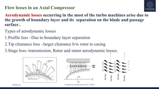
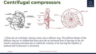
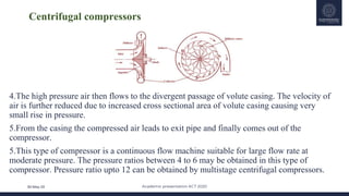
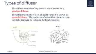
Academic presentation KCT 2020
30-May-20
Department of
Aeronautical Engineering
Since 2006
U18AEI5205
AIRCRAFT PROPULSION
Unit III Compressors
Session 2
Academic presentation KCT 2020
30-May-20 2
AIRCRAFT PROPULSION
Compressors
Part II
Academic presentation KCT 2020
30-May-20 3
COMPRESSORS
Compressible flow over moving vanes-Velocity diagram- Work
done –working principle of Axial and Centrifugal compressors –
Diffuser vane design considerations – Concepts of prewhirl,
Rotation stall –Degree of reaction –Performance characteristics-
Numerical problems.
Academic presentation KCT 2020
30-May-20
Flow losses in an Axial Compressor
Aerodynamic losses occurring in the most of the turbo machines arise due to
the growth of boundary layer and its separation on the blade and passage
surface .
Types of aerodynamic losses
1.Profile loss –Due to boundary layer separation
2.Tip clearance loss –larger clearance b/w rotor to casing
3.Stage loss- transmission, Rotor and stator aerodynamic losses.
Academic presentation KCT 2020
30-May-20
0ff-design operation
The performance of a compressor is defined according to its design. But in
actual practice, the operating point of the compressor deviates from the
design- point which is known as off-design operation.
Unstable flow in axial compressors can be due to two reasons.
1.Complete breakdown of steady through flow called surging.
2. Separation of flow from the blade surfaces called stalling.
Academic presentation KCT 2020
30-May-20
Compressor surge
• Surge is a reversal of flow and is a complete breakdown of the continuous
steady flow through the whole compressor. It results in mechanical damage
to the compressor due to the large fluctuations of flow which results in
changes in direction of the thrust forces on the rotor creating damage to the
blades.
• It is a form of unstable operation and should be avoided.
• Surge is the lower limit of stable operation in a compressor, and it involves
the reversal of flow due to aerodynamics instability within the system
• A decrease in the mass flow rate, an increase in the rotational speed of the
blade, or both can cause the compressor to surge.
• Operating at higher efficiency implies operation closer to surge.
Academic presentation KCT 2020
30-May-20
Academic presentation KCT 2020
30-May-20
Compressor Stall
There are three distinct stall phenomena.
• Individual blade stall
• Rotating stall
• Stall flutter
Individual Blade Stall
This type of stall occurs when all the blades around the compressor annulus stall
simultaneously without the occurrence of a stall propagation mechanism.
The circumstances under which individual blade stall is established are unknown at present.
Academic presentation KCT 2020
30-May-20
Rotating Stall
Rotating stall (propagating stall) consists of large stall zones covering several blade
passages and propagates in the direction of the rotation and at some fraction of rotor speed.
The number of stall zones and the propagating rates vary considerably .
This stalled blade does not produce a sufficient pressure rise to maintain the flow around it,
and an effective flow blockage or a zone of reduced flow develops.
Academic presentation KCT 2020
30-May-20
Stall Flutter
This phenomenon is caused by self-excitation of the blade and is an aero-elastic
phenomenon. Stall flutter is a phenomenon that occurs due to the stalling of the flow around
a blade.
Blade stall causes Karman vortices in the airfoil wake. Whenever the frequency of these
vortices coincides with the natural frequency of the airfoil, flutter will occur. Stall flutter is a
major cause of compressor blade failure.
Academic presentation KCT 2020
30-May-20 11
Effects of stall
• This reduces efficiency of the compressor
• Forced vibrations in the blades due to passage through stall compartment.
• These forced vibrations may match with the natural frequency of the
blades causing resonance and hence failure of the blade.
Academic presentation KCT 2020
30-May-20 12
Academic presentation KCT 2020
30-May-20
Centrifugal compressors
1.It consists of a rotating element
called impeller and a volute casing.
2.The air enters into the compressor
through the suction eye of the impeller.
Due to the rotation of the impeller at a
high speed produces centrifugal force
which causes the air to move out of the
impeller at a high velocity.
Academic presentation KCT 2020
30-May-20
Centrifugal compressors
3.Then the air with high velocity enters into a diffuser ring. The diffuser blades of the
diffuser ring are so shaped that these provide an increased area of passage to the air
which is passing outwards due to which the velocity of air leaving the impeller is
reduced and its pressure is increased.
Academic presentation KCT 2020
30-May-20
4.The high pressure air then flows to the divergent passage of volute casing. The velocity of
air is further reduced due to increased cross sectional area of volute casing causing very
small rise in pressure.
5.From the casing the compressed air leads to exit pipe and finally comes out of the
compressor.
5.This type of compressor is a continuous flow machine suitable for large flow rate at
moderate pressure. The pressure ratios between 4 to 6 may be obtained in this type of
compressor. Pressure ratio upto 12 can be obtained by multistage centrifugal compressors.
Centrifugal compressors
Academic presentation KCT 2020
30-May-20
Academic presentation KCT 2020
30-May-20
Academic presentation KCT 2020
30-May-20
Types of diffuser
• The diffuser consists of any annular space known as a
vaneless diffuser.
• The diffuser consists of a set of guide vanes it is known as
vanned diffuser . The main aim of this diffuser is to increase
the static pressure by reducing the kinetic energy.
Academic presentation KCT 2020
30-May-20
Pressure rise across
compressor
1
2
3
Inlet
Casing
Impeller
Diffuser
P
Channel
0
Academic presentation KCT 2020
30-May-20
Ideal energy transfer
Considered an ideal compressor with the following assumptions for
radial vanned impeller.
1. Losses due to friction are negligible
2. Energy loss or gain due to heat transfer to or from the gas is
considered very small.
3. The gas leaves the impeller with a tangential velocity equal to the
impeller velocity, no slip condition is assumed.(ct2=u2)
4. The air enters the rotor directly from the atmosphere without
tangential component.ct1= 0
Academic presentation KCT 2020
30-May-20
Ideal energy transfer
Euler's energy equation under ideal conditions becomes.
E = ct2u2-ct1u1 (or)
E = ½{(c2
2 – c1
2)+(u2
2 – u1
2)+(w1
2 - w2
2)}
E = u2
2
This is the maximum energy transfer that is possible. therefore the
work done by the impeller on unit quantity of air is given by
W = E = u2
2
Academic presentation KCT 2020
30-May-20
• Energy transfer equation from thermodynamic analysis
W = E = h02 - h01 = Cp(T02 – T01 )= Cp T01(rc
(γ-1/γ) -1)
u2
2 = Cp T01(rc
(γ-1/γ) -1)
Blade shapes and velocity triangles
In order to understand the actual energy transfer and flow
through compressor we will use two velocity triangles.
1.Entry velocity triangles
2.Exit velocity triangles
The absolute and relative air angles at entry and exit of the
impeller are denoted by α1, α2 and β1, β2.
Based on the value of β2 the blade shapes are given the name as
forward curved blades (β2>90),Radial blades (β2=90),Backward
curved blades(β2<90).
Academic presentation KCT 2020
30-May-20
Types of impeller blade
• The blades of the compressor or either forward curved or backward curved
or radial. Backward curved blades were used in the older compressors,
whereas the modern centrifugal compressors use mostly radial blades.
Academic presentation KCT 2020
30-May-20
• Since the change in radius between the entry and exit of the
impeller is large the impeller velocities at these stations are
different.
u1 =2𝜋𝑟1𝑁 /60
u2 =2𝜋𝑟2 𝑁/60
Academic presentation KCT 2020
30-May-20
Slip factor
It is the ratio b/w actual and ideal values of the whirl
component at the exit of the impeller.
μ = ct2
ct2’
Slip velocity Cs = ct2’ - ct2
if the value of slip factor is 1 then the slip velocity is
zero(no slip condition)
Academic presentation KCT 2020
30-May-20
Performance parameters
Power input factor
In practice the actual energy transfer to the air from the
impeller is lower than the ideal energy transfer ,because some energy
is lost in friction b/w the casing and the air carried round by vanes and
in disc friction.in order to take this into account power input factor is
introduced, so the actual energy transfer becomes.
E =Pif μ u2
2 Pif value lies b/w 1.035-1.04
Total head temperature rise across the compressor or temperature rise
across the impeller
ΔTc = T02 - T01 = Pif μ u2
2
Cp
Academic presentation KCT 2020
30-May-20
Pressure coefficient :
ψp = Wactual
Wisen
ψp = Cp T01(rc
(γ-1/γ) -1)
Cp T01(rcm
(γ-1/γ) -1)
ψp = Cp T01(rc
(γ-1/γ) -1)
u2
2
Academic presentation KCT 2020
30-May-20
Compressor efficiency :
It is the ratio b/w ideal enthalpy
difference to the actual enthalpy difference.
ɳc = (T02’ – T01 ) = Cp T01(rc
(γ-1/γ) -1)
(T02 – T01 ) Cp (T02 – T01 )
ɳc = ψp
Pif μ
Academic presentation KCT 2020
30-May-20
Academic presentation KCT 2020
30-May-20
Air–fuel equivalence ratio (λ) Air–fuel equivalence ratio, is the ratio of actual AFR to stoichiometry
for a given mixture. λ = 1.0 is at stoichiometry, rich mixtures λ < 1.0, and lean mixtures λ > 1.0. There
is a direct relationship between λ and AFR.
Academic presentation KCT 2020
30-May-20 31

Aircraft Compressor Part II.pptx

  • 1.
    Academic presentation KCT2020 30-May-20 Department of Aeronautical Engineering Since 2006 U18AEI5205 AIRCRAFT PROPULSION Unit III Compressors Session 2
  • 2.
    Academic presentation KCT2020 30-May-20 2 AIRCRAFT PROPULSION Compressors Part II
  • 3.
    Academic presentation KCT2020 30-May-20 3 COMPRESSORS Compressible flow over moving vanes-Velocity diagram- Work done –working principle of Axial and Centrifugal compressors – Diffuser vane design considerations – Concepts of prewhirl, Rotation stall –Degree of reaction –Performance characteristics- Numerical problems.
  • 4.
    Academic presentation KCT2020 30-May-20 Flow losses in an Axial Compressor Aerodynamic losses occurring in the most of the turbo machines arise due to the growth of boundary layer and its separation on the blade and passage surface . Types of aerodynamic losses 1.Profile loss –Due to boundary layer separation 2.Tip clearance loss –larger clearance b/w rotor to casing 3.Stage loss- transmission, Rotor and stator aerodynamic losses.
  • 5.
    Academic presentation KCT2020 30-May-20 0ff-design operation The performance of a compressor is defined according to its design. But in actual practice, the operating point of the compressor deviates from the design- point which is known as off-design operation. Unstable flow in axial compressors can be due to two reasons. 1.Complete breakdown of steady through flow called surging. 2. Separation of flow from the blade surfaces called stalling.
  • 6.
    Academic presentation KCT2020 30-May-20 Compressor surge • Surge is a reversal of flow and is a complete breakdown of the continuous steady flow through the whole compressor. It results in mechanical damage to the compressor due to the large fluctuations of flow which results in changes in direction of the thrust forces on the rotor creating damage to the blades. • It is a form of unstable operation and should be avoided. • Surge is the lower limit of stable operation in a compressor, and it involves the reversal of flow due to aerodynamics instability within the system • A decrease in the mass flow rate, an increase in the rotational speed of the blade, or both can cause the compressor to surge. • Operating at higher efficiency implies operation closer to surge.
  • 7.
  • 8.
    Academic presentation KCT2020 30-May-20 Compressor Stall There are three distinct stall phenomena. • Individual blade stall • Rotating stall • Stall flutter Individual Blade Stall This type of stall occurs when all the blades around the compressor annulus stall simultaneously without the occurrence of a stall propagation mechanism. The circumstances under which individual blade stall is established are unknown at present.
  • 9.
    Academic presentation KCT2020 30-May-20 Rotating Stall Rotating stall (propagating stall) consists of large stall zones covering several blade passages and propagates in the direction of the rotation and at some fraction of rotor speed. The number of stall zones and the propagating rates vary considerably . This stalled blade does not produce a sufficient pressure rise to maintain the flow around it, and an effective flow blockage or a zone of reduced flow develops.
  • 10.
    Academic presentation KCT2020 30-May-20 Stall Flutter This phenomenon is caused by self-excitation of the blade and is an aero-elastic phenomenon. Stall flutter is a phenomenon that occurs due to the stalling of the flow around a blade. Blade stall causes Karman vortices in the airfoil wake. Whenever the frequency of these vortices coincides with the natural frequency of the airfoil, flutter will occur. Stall flutter is a major cause of compressor blade failure.
  • 11.
    Academic presentation KCT2020 30-May-20 11 Effects of stall • This reduces efficiency of the compressor • Forced vibrations in the blades due to passage through stall compartment. • These forced vibrations may match with the natural frequency of the blades causing resonance and hence failure of the blade.
  • 12.
    Academic presentation KCT2020 30-May-20 12
  • 13.
    Academic presentation KCT2020 30-May-20 Centrifugal compressors 1.It consists of a rotating element called impeller and a volute casing. 2.The air enters into the compressor through the suction eye of the impeller. Due to the rotation of the impeller at a high speed produces centrifugal force which causes the air to move out of the impeller at a high velocity.
  • 14.
    Academic presentation KCT2020 30-May-20 Centrifugal compressors 3.Then the air with high velocity enters into a diffuser ring. The diffuser blades of the diffuser ring are so shaped that these provide an increased area of passage to the air which is passing outwards due to which the velocity of air leaving the impeller is reduced and its pressure is increased.
  • 15.
    Academic presentation KCT2020 30-May-20 4.The high pressure air then flows to the divergent passage of volute casing. The velocity of air is further reduced due to increased cross sectional area of volute casing causing very small rise in pressure. 5.From the casing the compressed air leads to exit pipe and finally comes out of the compressor. 5.This type of compressor is a continuous flow machine suitable for large flow rate at moderate pressure. The pressure ratios between 4 to 6 may be obtained in this type of compressor. Pressure ratio upto 12 can be obtained by multistage centrifugal compressors. Centrifugal compressors
  • 16.
  • 17.
  • 18.
    Academic presentation KCT2020 30-May-20 Types of diffuser • The diffuser consists of any annular space known as a vaneless diffuser. • The diffuser consists of a set of guide vanes it is known as vanned diffuser . The main aim of this diffuser is to increase the static pressure by reducing the kinetic energy.
  • 19.
    Academic presentation KCT2020 30-May-20 Pressure rise across compressor 1 2 3 Inlet Casing Impeller Diffuser P Channel 0
  • 20.
    Academic presentation KCT2020 30-May-20 Ideal energy transfer Considered an ideal compressor with the following assumptions for radial vanned impeller. 1. Losses due to friction are negligible 2. Energy loss or gain due to heat transfer to or from the gas is considered very small. 3. The gas leaves the impeller with a tangential velocity equal to the impeller velocity, no slip condition is assumed.(ct2=u2) 4. The air enters the rotor directly from the atmosphere without tangential component.ct1= 0
  • 21.
    Academic presentation KCT2020 30-May-20 Ideal energy transfer Euler's energy equation under ideal conditions becomes. E = ct2u2-ct1u1 (or) E = ½{(c2 2 – c1 2)+(u2 2 – u1 2)+(w1 2 - w2 2)} E = u2 2 This is the maximum energy transfer that is possible. therefore the work done by the impeller on unit quantity of air is given by W = E = u2 2
  • 22.
    Academic presentation KCT2020 30-May-20 • Energy transfer equation from thermodynamic analysis W = E = h02 - h01 = Cp(T02 – T01 )= Cp T01(rc (γ-1/γ) -1) u2 2 = Cp T01(rc (γ-1/γ) -1) Blade shapes and velocity triangles In order to understand the actual energy transfer and flow through compressor we will use two velocity triangles. 1.Entry velocity triangles 2.Exit velocity triangles The absolute and relative air angles at entry and exit of the impeller are denoted by α1, α2 and β1, β2. Based on the value of β2 the blade shapes are given the name as forward curved blades (β2>90),Radial blades (β2=90),Backward curved blades(β2<90).
  • 23.
    Academic presentation KCT2020 30-May-20 Types of impeller blade • The blades of the compressor or either forward curved or backward curved or radial. Backward curved blades were used in the older compressors, whereas the modern centrifugal compressors use mostly radial blades.
  • 24.
    Academic presentation KCT2020 30-May-20 • Since the change in radius between the entry and exit of the impeller is large the impeller velocities at these stations are different. u1 =2𝜋𝑟1𝑁 /60 u2 =2𝜋𝑟2 𝑁/60
  • 25.
    Academic presentation KCT2020 30-May-20 Slip factor It is the ratio b/w actual and ideal values of the whirl component at the exit of the impeller. μ = ct2 ct2’ Slip velocity Cs = ct2’ - ct2 if the value of slip factor is 1 then the slip velocity is zero(no slip condition)
  • 26.
    Academic presentation KCT2020 30-May-20 Performance parameters Power input factor In practice the actual energy transfer to the air from the impeller is lower than the ideal energy transfer ,because some energy is lost in friction b/w the casing and the air carried round by vanes and in disc friction.in order to take this into account power input factor is introduced, so the actual energy transfer becomes. E =Pif μ u2 2 Pif value lies b/w 1.035-1.04 Total head temperature rise across the compressor or temperature rise across the impeller ΔTc = T02 - T01 = Pif μ u2 2 Cp
  • 27.
    Academic presentation KCT2020 30-May-20 Pressure coefficient : ψp = Wactual Wisen ψp = Cp T01(rc (γ-1/γ) -1) Cp T01(rcm (γ-1/γ) -1) ψp = Cp T01(rc (γ-1/γ) -1) u2 2
  • 28.
    Academic presentation KCT2020 30-May-20 Compressor efficiency : It is the ratio b/w ideal enthalpy difference to the actual enthalpy difference. ɳc = (T02’ – T01 ) = Cp T01(rc (γ-1/γ) -1) (T02 – T01 ) Cp (T02 – T01 ) ɳc = ψp Pif μ
  • 29.
  • 30.
    Academic presentation KCT2020 30-May-20 Air–fuel equivalence ratio (λ) Air–fuel equivalence ratio, is the ratio of actual AFR to stoichiometry for a given mixture. λ = 1.0 is at stoichiometry, rich mixtures λ < 1.0, and lean mixtures λ > 1.0. There is a direct relationship between λ and AFR.
  • 31.
    Academic presentation KCT2020 30-May-20 31