Download to read offline

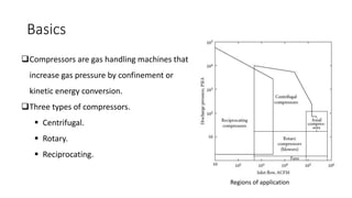
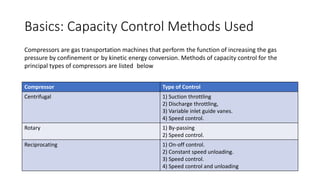
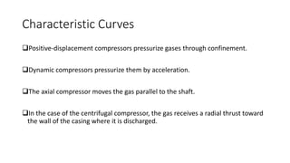
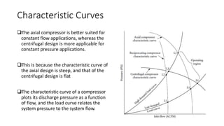
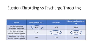
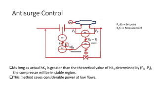

The document outlines a course focused on compressor control and optimization, educating students on types of compressors, their capacity control methods, and the implications of surge phenomena. It details the operational principles of centrifugal, rotary, and reciprocating compressors, along with various throttling methods and their efficiencies in different systems. Additionally, it explains surge control mechanisms and critical operating parameters to ensure stable compressor performance.


![Electronic fuel injection system [EFI]](https://cdn.slidesharecdn.com/ss_thumbnails/efibilkulfinal-171227111232-thumbnail.jpg?width=640&height=640&fit=bounds)


