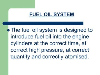
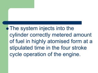
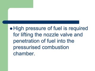
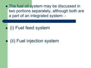
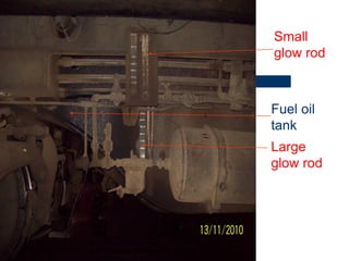
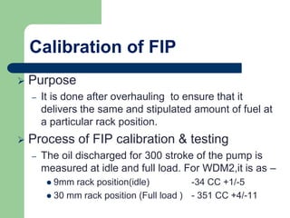
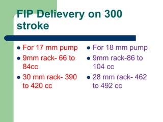
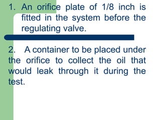
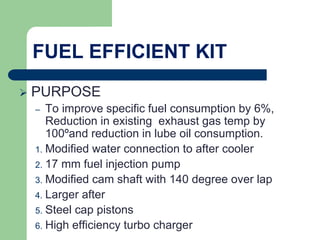
The document discusses the fuel oil system on a locomotive engine. It describes the fuel feed system and fuel injection system.
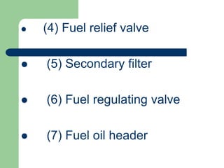
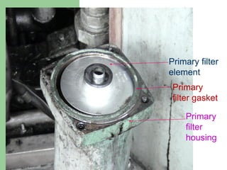
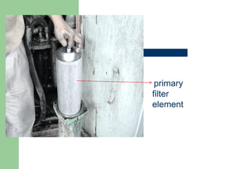
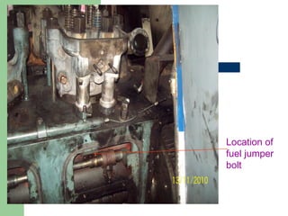
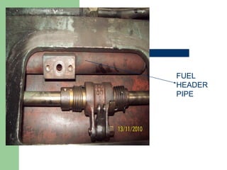
The fuel feed system supplies fuel oil from the tank to the injection system at high pressure. It includes a primary filter, fuel pump, secondary filter, and fuel header piping. The fuel injection system atomizes and injects the fuel into the cylinders. It consists of high-pressure fuel injectors and fuel injection pumps that deliver fuel at precise timings and quantities. Proper functioning and testing of these systems is important for complete combustion and engine performance.
Classification of fuel injectors and nozzleVaibhav Patil
Fuel injectors atomize the fuel into very fine droplets, and increases the surface area of the fuel droplets resulting in better mixing and subsequent combustion Atomization is done by forcing the fuel through a small orifice under high pressure.
In the hydrocarbon processing and production industry, gas is compressed for transportation to consuming markets and for use in processing operations. This presentation is about the construction and operation of compressors.
In this presentation you will learn about the construction and operation of centrifugal compressors.
This slides are about inline injection pump and calibration of the pumps .The working of the pump is described in simple words and with examples of daily usable devices.
AYB Mechatronics holds ISO 9001:2008 certification.With more than 10000 part numbers in stock, AYB Mechatronics offers its customers the best possible service in the replacement parts industry.
ICE_Handout(5) for CI fuel injection.pdf20007134009
FUEL INJECTION SYSTEM FOR CI ENGINES
The function of a fuel injection system is to meter the appropriate quantity of fuel for the given
engine speed and load to each cylinder, each cycle, and inject that fuel at the appropriate time in the
cycle at the desired rate with the spray configuration required for the particular combustion
chamber employed. It is important that injection begin and end cleanly, and avoid any secondary
injections. To accomplish this function, fuel is usually drawn from the fuel tank by a supply pump,
and forced through a filter to the injection pump. The injection pump sends fuel under pressure to
the nozzle pipes which carry fuel to the injector nozzles located in each cylinder head. Excess fuel
goes back to the fuel tank. CI engines are operated unthrottled, with engine speed and power
controlled by the amount of fuel injected during each cycle. This allows for high volumetric
efficiency at all speeds, with the intake system designed for very little flow restriction of the
incoming air.
FUNCTIONAL REQUIREMENTS OF AN INJECTION SYSTEM
For a proper running and good performance of the engine, the following requirements must be met
by the injection system:
• Accurate metering of the fuel injected per cycle. Metering errors may cause drastic variation
from the desired output. The quantity of the fuel metered should vary to meet changing speed
and load requirements of the engine.
• Correct timing of the injection of the fuel in the cycle so that maximum power is obtained.
• Proper control of rate of injection so that the desired heat-release pattern is achieved during
combustion.
• Proper atomization of fuel into very fine droplets.
• Proper spray pattern to ensure rapid mixing of fuel and air.
• Uniform distribution of fuel droplets throughout the combustion chamber
• To supply equal quantities of metered fuel to all cylinders in case of multi-cylinder engines.
• No lag during beginning and end of injection i.e., to eliminate dribbling of fuel droplets into the
cylinder.
TYPES OF INJECTION SYSTEMS
There are basically two types of injection systems: Air injection system and solid injection system.
Air Injection System: In this system, fuel is forced into the cylinder by means of compressed air.
This system is little used nowadays, because it requires a bulky multi-stage air compressor. This
causes an increase in engine weight and reduces the brake power output further. One advantage that
is claimed for the air injection system is good mixing of fuel with the air resulting in higher mean
effective pressure. Another advantage is its ability to utilize fuels of high viscosity which are less
expensive than those used by the engines with solid injection systems. These advantages are off-set
by the requirement of a multistage compressor thereby making the air-injection system obsolete.
Solid Injection System: In this system the liquid fuel is injected directly in.
Unit Injector System: In this syst
UNIT-II-ENGINE AUXILIARY SYSTEMS &TURBOCHARGERDineshKumar4165
Electronically controlled gasoline injection system for SI engines, Electronically controlled diesel injection system, Unit injector system, Rotary distributor type and common rail direct injection system, Electronic ignition system - Transistorized coil ignition system, capacitive discharge ignition system, Turbo chargers -Waste Gate Turbocharger, Variable Geomentry Turbocharger, Engine emission control by three way catalytic converter system, Emission norms (Euro and BS).
Automobile Engineering Unit 2 - Anna universitysuresh n
The 2nd unit of automobile engineering describe about carburetor, types of carburetor, ignition system such as coil ignition, magneto ignition and electric ignition system. And also it describe about supercharger and turbocharger
Harnessing WebAssembly for Real-time Stateless Streaming PipelinesChristina Lin
Traditionally, dealing with real-time data pipelines has involved significant overhead, even for straightforward tasks like data transformation or masking. However, in this talk, we’ll venture into the dynamic realm of WebAssembly (WASM) and discover how it can revolutionize the creation of stateless streaming pipelines within a Kafka (Redpanda) broker. These pipelines are adept at managing low-latency, high-data-volume scenarios.
NUMERICAL SIMULATIONS OF HEAT AND MASS TRANSFER IN CONDENSING HEAT EXCHANGERS...ssuser7dcef0
Power plants release a large amount of water vapor into the
atmosphere through the stack. The flue gas can be a potential
source for obtaining much needed cooling water for a power
plant. If a power plant could recover and reuse a portion of this
moisture, it could reduce its total cooling water intake
requirement. One of the most practical way to recover water
from flue gas is to use a condensing heat exchanger. The power
plant could also recover latent heat due to condensation as well
as sensible heat due to lowering the flue gas exit temperature.
Additionally, harmful acids released from the stack can be
reduced in a condensing heat exchanger by acid condensation. reduced in a condensing heat exchanger by acid condensation.
Condensation of vapors in flue gas is a complicated
phenomenon since heat and mass transfer of water vapor and
various acids simultaneously occur in the presence of noncondensable
gases such as nitrogen and oxygen. Design of a
condenser depends on the knowledge and understanding of the
heat and mass transfer processes. A computer program for
numerical simulations of water (H2O) and sulfuric acid (H2SO4)
condensation in a flue gas condensing heat exchanger was
developed using MATLAB. Governing equations based on
mass and energy balances for the system were derived to
predict variables such as flue gas exit temperature, cooling
water outlet temperature, mole fraction and condensation rates
of water and sulfuric acid vapors. The equations were solved
using an iterative solution technique with calculations of heat
and mass transfer coefficients and physical properties.
Water billing management system project report.pdfKamal Acharya
Our project entitled “Water Billing Management System” aims is to generate Water bill with all the charges and penalty. Manual system that is employed is extremely laborious and quite inadequate. It only makes the process more difficult and hard.
The aim of our project is to develop a system that is meant to partially computerize the work performed in the Water Board like generating monthly Water bill, record of consuming unit of water, store record of the customer and previous unpaid record.
We used HTML/PHP as front end and MYSQL as back end for developing our project. HTML is primarily a visual design environment. We can create a android application by designing the form and that make up the user interface. Adding android application code to the form and the objects such as buttons and text boxes on them and adding any required support code in additional modular.
MySQL is free open source database that facilitates the effective management of the databases by connecting them to the software. It is a stable ,reliable and the powerful solution with the advanced features and advantages which are as follows: Data Security.MySQL is free open source database that facilitates the effective management of the databases by connecting them to the software.
Hierarchical Digital Twin of a Naval Power SystemKerry Sado
A hierarchical digital twin of a Naval DC power system has been developed and experimentally verified. Similar to other state-of-the-art digital twins, this technology creates a digital replica of the physical system executed in real-time or faster, which can modify hardware controls. However, its advantage stems from distributing computational efforts by utilizing a hierarchical structure composed of lower-level digital twin blocks and a higher-level system digital twin. Each digital twin block is associated with a physical subsystem of the hardware and communicates with a singular system digital twin, which creates a system-level response. By extracting information from each level of the hierarchy, power system controls of the hardware were reconfigured autonomously. This hierarchical digital twin development offers several advantages over other digital twins, particularly in the field of naval power systems. The hierarchical structure allows for greater computational efficiency and scalability while the ability to autonomously reconfigure hardware controls offers increased flexibility and responsiveness. The hierarchical decomposition and models utilized were well aligned with the physical twin, as indicated by the maximum deviations between the developed digital twin hierarchy and the hardware.
TOP 10 B TECH COLLEGES IN JAIPUR 2024.pptxnikitacareer3
Looking for the best engineering colleges in Jaipur for 2024?
Check out our list of the top 10 B.Tech colleges to help you make the right choice for your future career!
1) MNIT
2) MANIPAL UNIV
3) LNMIIT
4) NIMS UNIV
5) JECRC
6) VIVEKANANDA GLOBAL UNIV
7) BIT JAIPUR
8) APEX UNIV
9) AMITY UNIV.
10) JNU
TO KNOW MORE ABOUT COLLEGES, FEES AND PLACEMENT, WATCH THE FULL VIDEO GIVEN BELOW ON "TOP 10 B TECH COLLEGES IN JAIPUR"
https://www.youtube.com/watch?v=vSNje0MBh7g
VISIT CAREER MANTRA PORTAL TO KNOW MORE ABOUT COLLEGES/UNIVERSITITES in Jaipur:
https://careermantra.net/colleges/3378/Jaipur/b-tech
Get all the information you need to plan your next steps in your medical career with Career Mantra!
https://careermantra.net/
Literature Review Basics and Understanding Reference Management.pptxDr Ramhari Poudyal
Three-day training on academic research focuses on analytical tools at United Technical College, supported by the University Grant Commission, Nepal. 24-26 May 2024
Using recycled concrete aggregates (RCA) for pavements is crucial to achieving sustainability. Implementing RCA for new pavement can minimize carbon footprint, conserve natural resources, reduce harmful emissions, and lower life cycle costs. Compared to natural aggregate (NA), RCA pavement has fewer comprehensive studies and sustainability assessments.
2. FUEL OIL SYSTEM
The fuel oil system is designed to
introduce fuel oil into the engine
cylinders at the correct time, at
correct high pressure, at correct
quantity and correctly atomised.
3. The system injects into the
cylinder correctly metered amount
of fuel in highly atomised form at a
stipulated time in the four stroke
cycle operation of the engine.
4. High pressure of fuel is required
for lifting the nozzle valve and
penetration of fuel into the
pressurised combustion
chamber.
5. High pressure also helps in proper
atomization so that the small
droplets come in better contact
with the fresh air in combustion
chamber and thus have better
combustion.
6. Metering the fuel to correct
required quantity is important
because the locomotive engine is
a variable speed and variable load
engine with variable requirement of
fuel within a particular range.
7. Timing the injection of fuel is
also important to enable fuel to
burn completely for maximum
benefit out of it.
8. The fuel oil system may be discussed in
two portions separately, although both are
a part of an integrated system: -
(i) Fuel feed system
(ii) Fuel injection system
9. FUEL FEED SYSTEM
The fuel feed system includes the
following: -
(1) Fuel oil tank
(2) Fuel primary filter
(3) Fuel transfer pump / fuel booster
pump
11. FUEL OIL TANK
The fuel oil tank of 5000 ltrs capacity is
fabricated under the superstructure of the
locomotive and located in between two
bogies.
14. Baffle walls are there inside it to
arrest surge of oil when the
locomotive is moving.
A strainer filter at the filling plug, an
indirect vent, drain plug and glo-rod
type level indicators are also
provided.
16. PRIMARY FILTER
A filter is provided on the suction
side of the fuel transfer pump to
allow only filtered oil getting into
the pump. This is intended to
enhance the life of the Fuel
transfer pump.
21. filter is coarse type filter and have
greater ability to absorb moisture
and on cost cheaper. However in
certain places this has been
replaced by paper type filters
which have longer service life.
22. The fuel oil feed system has a transfer pump
or booster pump to lift the fuel from the tank
below to the system. The gear type pump
used is driven by a D.C. motor with current
available from the storage batteries
through a suitable circuit. The pump
capacity is 14 ltrs. per minute at 1725 rpm at
pressure 4 to 4.8 kg/cm. sq.
FUEL TRANSFER PUMP / BOOSTER
PUMP
24. FUEL RELIEF VALVE
The spring loaded relief valve is meant for
by-passing excess oil back to the fuel
tank, thus releasing excess load on the
pump and the motor to ensure their safety.
It is adjusted to a pressure of 5.2-kg/cm.
sq. and by-passes the excess fuel back
to the tank. It also ensures the safety of
the secondary filter and the pipe lines.
25. FUEL SECONDARY FILTER
The fuel secondary filter is located after
the booster pump in the fuel feed system.
The filter used is a paper type filter
cartridge of finer quality, renewable at
regular intervals. This filter arrests the
finer dirt particles left over by the primary
filter and ensure longer life of the fuel
injection equipments.
26. The fuel-regulating valve is a
spring-loaded valve of similar
design like the fuel relief valve
but located after the secondary
filter in the fuel feed system.
FUEL REGULATING VALVE
27. This valve is adjusted to 3.6-kg/cm.
sq. pressure and always maintains the
same pressure in the fuel feed system
by releasing the excess pressure, if
any, back to the fuel oil tank. There is
no by-passing of oil if the pressure is
less than the adjusted level.
28. FUNCTIONING OF FUEL FEED
SYSTEM
The fuel booster pump or transfer pump
is switched on and the pump starts
sucking oil from the fuel oil tank, filtered
through the primary filter. Because of
variable consumption by the engine, the
delivery pressure of the pump may rise
increasing load on the pump and its
drive motor.
29. When the rate of consumption of fuel
by the engine is low,
the relief valve ensures the safety of
the components by releasing load, by-
passing the excess pressure back to
the tank. Then oil passes through the
paper type secondary filter and
proceeds to the left side fuel header.
30. The fuel header is connected to eight
numbers of fuel injection pumps on the
left bank of the engine,
and a steady oil supply is maintained
to the pumps at a pressure of 3.6-
kg/cm. Sq. Then the fuel oil passes on
to the right side header and reaches
the eight fuel injection pumps on the
right bank through jumper pipes.
36. The regulating valve remaining after the
right side fuel header, takes care of
excess pressure over 3.6 kg/cm. sq
by-passing the extra oil back to the tank.
A gauge connection is taken from here
leading to the driver's cabin for indicating
the fuel oil feed pressure. Thus the fuel
feed system keeps fuel continuously
available to the fuel injection pumps,
which the pumps may use or refuse
depending on the demand of the engine.
40. Fuel Injection
To inject fuel at a sufficiently high
pressure so that the fuel enters the
cylinder with a high velocity.
Fuel injection nozzle injects fuel oil
to combustion chamber at 3900-
4000psi
43. Testing of F/INJECTOR
The following tests are conducted on a
specially designed machine-
– Spray pressure (3900-4050 PSI for new & 3600-
3800 PSI for reconditioned nozzle)
– Spray pattern( 9,by taking impression on blotting
paper)
– Dribbling (at 3500PSI for 10 sec)
– Nozzle chatter
– Nozzle leak off rate(3500PSI to 1000PSI in 9 to
19sec)
44. FUEL INJECTION NOZZLE INSPECTION
AND MAINTENANCE
The criteria for good nozzle is good
atomization, correct spray pattern and no
leakage or dribbling. Before a nozzle is put
to test the assembly must be rinsed in fuel oil,
nozzle holes cleaned with wire brush and spray
holes cleaned with steel wire of correct
thickness.
The fuel injection nozzles are tested on a
specially designed machine shown in FIG-FIS-
16 where the following tests are conducted.
45. SPRAY PATTERN
Spray of fuel should take place through all the holes
uniformly and properly atomised. While the atomization can be
seen through the glass jar, an impression taken on a sheet of
blotting paper at a distance of 1 to 1 ½ inch also gives
a clear impression of the spray pattern.
SPRAY PRESSURE
The stipulated correct pressure at which the spray should
take place 3900-4050 psi for new and 3700-3800 psi for
reconditioned nozzles. If the pressure is down to 3600 psi the
nozzle needs replacement. The spray pressure is indicated in
the gauge provided in the test machine. Shims are being used
to increase or decrease the tension of nozzle spring which
increases or decreases the spray pressure
46. DRIBBLING
There should be no loose drops of fuel coming out of the
nozzle before or after the injections. In fact the nozzle tip of a
good nozzle should always remain dry. The process of checking
dribbling during testing is by having injections manually done
couple of times quickly and check the nozzle tip whether leaky.
Raising the pressure within 100 psi of set injection pressure
and holding it for about 10 seconds may also give a clear idea of
the nozzle dribbling, if any.
The reasons of nozzle dribbling are 1) Improper pressure
setting 2) Dirt stuck up between the valve and the valve seat 3)
Improper contact between the valve and valve seat 4) Valve
sticking inside the valve body.
NOZZLE CHATTER
The chattering sound is a sort of cracking noise created due to
free movement of the nozzle valve inside the valve body. If the
chatter is not proper then chances are that the valve is not moving
freely inside the nozzle.
47. NOZZLE LEAK OFF RATE
A very minute portion of the oil inside the nozzle passes
through the clearance between the valve and the valve body
for the purpose of lubrication. Excess clearance between
them may cause excess leak off, thus reducing the amount of
fuel actually injected.
The process of checking the leak off rate is by creating
pressure in the nozzle up to 3500 psi and hold the pressure till
it drops to 1000 psi. The drop of pressures is due to the leak
off and higher the leak off rate the pressure drop is quicker. In
the event of the leak off time recorded below stipulation the
nozzle valve and the valve body have to be changed for
excessive wear and clearance between them.
48. Fuel Injection Pump
It is single acting constant stroke
plunger type pump.
Function-
Raise the fuel oil pressure to nozzle to
atomize the fuel.
Supply the correct quantity of fuel to nozzle.
Deliver the fuel at accurate time.
49.
50. FIP-Major Parts
– Control Rack
– Barrel & plunger
– Control sleeve
– Plunger spring
– Guide cup
– Lower spring seat.
– Snubber valve assembly.
51.
52. Calibration of FIP
Purpose
– It is done after overhauling to ensure that it
delivers the same and stipulated amount of fuel at
a particular rack position.
Process of FIP calibration & testing
– The oil discharged for 300 stroke of the pump is
measured at idle and full load. For WDM2,it is as –
9mm rack position(idle) -34 CC +1/-5
30 mm rack position (Full load ) - 351 CC +4/-11
53. FIP Delievery on 300
stroke
For 17 mm pump
9mm rack- 66 to
84cc
30 mm rack- 390
to 420 cc
For 18 mm pump
9mm rack-86 to
104 cc
28 mm rack- 462
to 492 cc
54. Phasing of FIP
PHASING: Setting of Pump
according to Injection Timing.
55.
56. ORIFICE TEST
Purpose:
– This test is conducted to check the efficiency of
the fuel feed system under full load condition.
Process:
– Fit a orifice plate of 1/8 inch in the system before
the regulating V/V.
– Place a container to collect the leak off oil.
– Switch on the Fuel booster P/P for 60 sec.
– The rate of leak should be about 9 ltrs per minute.
57. 1. An orifice plate of 1/8 inch is
fitted in the system before the
regulating valve.
2. A container to be placed under
the orifice to collect the oil that
would leak through it during the
test.
58. 3. The fuel booster pump to be switched on for
60 seconds.
4. The rate of leakage should be about 9 Lts. of
fuel per minute through the orifice (with the engine in
stopped condition). The system should be able to
maintain 3 KG/cm pressure with this rate of
leakage which simulates approx. the full load
consumption by the engine. In the event of drop in
pressure the rate of leakage would also be less
indicating some defect in the system reducing its
efficiency to meet the full requirement of fuel during
peak load.
59. FUEL EFFICIENT KIT
PURPOSE
– To improve specific fuel consumption by 6%,
Reduction in existing exhaust gas temp by
100ºand reduction in lube oil consumption.
1. Modified water connection to after cooler
2. 17 mm fuel injection pump
3. Modified cam shaft with 140 degree over lap
4. Larger after
5. Steel cap pistons
6. High efficiency turbo charger
60. TROUBLES IN DIESEL ENGINE DUE
TO LOW GRADE FUEL OIL
The use of dirty and unsuitable fuel
frequently causes the following
troubles –
– Piston ring groove deposits
– Exhaust valve deposit
– Cylinder wall deposit
– Fuel pump wear
61. FUEL OIL TESTS AND SIGNIFICANCES
– Water contant (by Crackle test,0.05% by vol.)
– Viscosity ( Spray pattern affects)
– Carbon residue.(10% by mass)
– Sulphur content.(0.25% by mass, may cause corrosion in
engine parts)
– Cetane number( indicate ignition quality,45 )
– Specific gravity (Co-relates with calorific value of fuel so
tested at 15’C)
– Flash point(Temp.at which it gives sufficient vapour to form a
mixture with air).
– Colour comparison (with potassium dichromate solution)
62. Water contamination-effect
It causes corrosion of metal parts.
It form sludge, which may clog the
suction filter.
Ignition quality will be effected and
engine (connecting rod may bent)
may get fail.
63. Viscosity -effect
If high viscosity, Spray pattern will
be not satisfactory ,in resultant
combustion will be affected.
64. Carbon Residue-effect
It should be low as much as possible .
– Compression pressure will be affected.
– Rate of heat dissipation will reduce, in
resultant thermal load will come on parts
inside the combustion chamber and finally
thermal crack may occur.
65. Sulpher content-effect
It is injurious to F.O.System. (Max.
sulphur in % by mass-0.25)
Sulphur in fuel contribute to corrosion
of Fuel injection system ,Liner ,Piston
,Cylinder head, Valves.
66. Cetane Number-effect
– Delay period( time interval between
ignition & combustion) is to be
minimum.
– After burning will be occur.(in case of
excess cetane number)
67.
68. FACTORS LEADING TO GOOD
COMBUSTION
1.VISCOSITY:- It must be low enough to
ensure correct atomisation at the fuel
injection.
2. ATOMISATION:- splitting up the fuel
into very small droplets.