SlideShare a Scribd company logo
1 of 118
Download to read offline
Problem 5.1 In Active Example 5.1, suppose that the
beam is subjected to a 6kN-m counterclockwise couple
at the right end in addition to the 4-kN downward force.
Draw a sketch of the beam showing its new loading.
Draw the free-body diagram of the beam and apply the
equilibrium equations to determine the reactions at A.
4 kN
2 m
A
Solution: The equilibrium equations are
Fx : Ax D 0
Fy : Ay 4 kN D 0
MA : MA 4 kN 2 m
C 6 kN-m D 0
Solving yields
Ax D 0
Ay D 4 kN
MA D 2 kN-m
Problem 5.2 The beam has a fixed support at A and is
loaded by two forces and a couple. Draw the free-body
diagram of the beam and apply equilibrium to determine
the reactions at A.
2 kN4 kN
60ЊA
6 kN-m
1.5 m1.5 m1 m
Solution: The free-body diagram is drawn.
The equilibrium equations are
Fx : Ax C 2 kN cos 60° D 0
Fy : Ay C 4 kN C 2 kN sin 60° D 0
MA : MA C 6 kN-m C 4 kN 2.5 m C 2 kN sin 60° 4 m D 0
We obtain: Ax D 1 kN, Ay D 5.73 kN, MA D 22.9 kN-m
268
c 2008 Pearson Education South Asia Pte Ltd. All rights reserved. This publication is protected by Copyright and permission should be obtained from the publisher prior
to any prohibited reproduction, storage in a retrieval system, or transmission in any form or by any means, electronic, mechanical, photocopying, recording or likewise.
Problem 5.3 The beam is subjected to a load F D
400 N and is supported by the rope and the smooth
surfaces at A and B.
(a) Draw the free-body diagram of the beam.
(b) What are the magnitudes of the reactions at A
and B?
F
30°45°
A B
1.2 m 1.5 m 1 m
Solution:
FX D 0: A cos 45° B sin 30° D 0
FY D 0: A sin 45° C B cos 30° T 400 N D 0
C MA D 0: 1.2T 2.7 400 C 3.7B cos 30° D 0
Solving, we get
A D 271 N
B D 383 N
T D 124 N
x
y
1.2 m
1.5 m45°
30°T
1 m
B
FA
Problem 5.4 (a) Draw the free-body diagram of the
beam. (b) Determine the tension in the rope and the
reactions at B.
5 m 9 m
30Њ
30Њ
BA
600 N
Solution: Let T be the tension in the rope.
The equilibrium equations are:
Fx : T sin 30° 600 N sin 30° C Bx D 0
Fy : T cos 30° 600 N cos 30° C By D 0
MB : 600 N cos 30° 9 m T cos 30° 14 m D 0
Solving yields T D 368 N, Bx D 493 N, By D 186
269
N
600 N
9 m5 m
c 2008 Pearson Education South Asia Pte Ltd. All rights reserved. This publication is protected by Copyright and permission should be obtained from the publisher prior
to any prohibited reproduction, storage in a retrieval system, or transmission in any form or by any means, electronic, mechanical, photocopying, recording or likewise.
Problem 5.5 (a) Draw the free-body diagram of the
A and B
are smooth.
(b) Determine the reactions at A and B.
0
A B
30 N
0.25 m 0.35 m
Solution: The system is in equilibrium.
(a) The free body diagram is shown.
(b) The sum of the forces:
FX D 0, FY D FA C FB D 0
The sum of the moments about point A:
MA D C FB D 0,
from which FB D D
Substitute into the force balance equation:
FA D FB D
A B
FA FB
300 N
0.25 m 0.35 m
270
300 N drill press, assuming that the surfaces at
300
0.25 300 0.6
75
0.6
125 N
300 175 N
c 2008 Pearson Education South Asia Pte Ltd. All rights reserved. This publication is protected by Copyright and permission should be obtained from the publisher prior
to any prohibited reproduction, storage in a retrieval system, or transmission in any form or by any means, electronic, mechanical, photocopying, recording or likewise.
Problem 5.6 The masses of the person and the diving
board are 54 kg and 36 kg, respectively. Assume that
they are in equilibrium.
(a) Draw the free-body diagram of the diving board.
(b) Determine the reactions at the supports A and B.
WP
A B
WD
1.2 m
2.4 m
4.6 m
Solution:
(a)
(b) FX D 0: AX D 0
FY D 0: AY C BY 54 9.81 36 9.81 D 0
MA D 0: 1.2BY 2.4 36 9.81
4.6 54 9.81 D 0
Solving: AX D 0 N
AY D 1.85 kN
BY D 2.74 kN
AY
AX
BY WPWD
1.2 m
2.4 m
4.6 m
Problem 5.7 The ironing board has supports at A and
B that can be modeled as roller supports.
(a) Draw the free-body diagram of the ironing board.
(b) Determine the reactions at A and B.
y
x
A B
50 N 15 N
0.3 m 0.25 m 0.5 m
Solution: The system is in equilibrium.
(a) The free-body diagram is shown.
(b) The sums of the forces are:
FX D 0,
FY D FA C FB D 0.
The sum of the moments about A is
MA D FB D 0,
from which FB D
43.25
D
Substitute into the force balance equation:
FA D FB D
A B
y
x
FA FB
50 N
0.3 m
0.25 m
0.5 m 15 N
50 N 15 N
271
50 15
0.3 0.55 50 1.05 15
0.3
144.2 N
79.2 N65
c 2008 Pearson Education South Asia Pte Ltd. All rights reserved. This publication is protected by Copyright and permission should be obtained from the publisher prior
to any prohibited reproduction, storage in a retrieval system, or transmission in any form or by any means, electronic, mechanical, photocopying, recording or likewise.
Problem 5.8 The distance x D 9 m.
(a) Draw the free-body diagram of the beam.
(b) Determine the reactions at the supports.
10 kN
B
A
x
6 m
Solution:
(a) The FBD
(b) The equilibrium equations
Fx : Ax D 0
Fy : Ay C By 10 kN D 0
MA : By 6 m 10 kN 9 m D 0
Solving we find
Ax D 0, Ay D 5 kN, By D 15 kN
10 kN
6 m
Ax
Ay
By
x = 9 m
Problem 5.9 In Example 5.2, suppose that the 200-N
downward force and the 300 N-m counterclockwise
couple change places; the 200-N downward force acts
at the right end of the horizontal bar, and the 300 N-m
counterclockwise couple acts on the horizontal bar 2
to the right of the support A. Draw a sketch of the object
showing the new loading. Draw the free-body diagram
of the object and apply the equilibrium equations to
determine the reactions at A. 2 m
2 m
2 m
300 -
2
100 N
200 N
A
30
N m
m
Solution: The sketch and free-body diagram are shown.
The equilibrium equations are
Fx : Ax C 100 N cos 30° D 0
Fy : Ay C 100 N sin 30° 200 ND 0
MA : MA C 300 N-m
C 100 N sin 30° 4 m
100 N cos 30° 2 m
200 N 6 m D 0
We obtain
Ax D 86.6 N
Ay D 150 N
MA D 873 -
272
m
N m
2 m2 m 2 m
100 N
200 N300 N-m 2 m
300 N-m
2 m2 m 2 m
100 N
200 N2 m
c 2008 Pearson Education South Asia Pte Ltd. All rights reserved. This publication is protected by Copyright and permission should be obtained from the publisher prior
to any prohibited reproduction, storage in a retrieval system, or transmission in any form or by any means, electronic, mechanical, photocopying, recording or likewise.
Problem 5.10 (a) Draw the free-body diagram of the
beam.
(b) Determine the reactions at the supports.
100 N 400 N
BA
900 N-m
3 m 4 m 3 m 4 m
Solution: (a) Both supports are roller supports. The free body
diagram is shown. (b) The sum of the forces:
FX D 0,
and FY D FA C FB C 100 400 D 0.
The sum of the moments about A is
MA D 3 100 C 900 7 400 C 11FB D 0.
From which FB D
2200
11
D 200 N
Substitute into the force balance equation to obtain
FA D 300 FB D 100
3 m
3 m
3 m
3 m
900
900 N-m BA
4 m
4 4
4 m
FA FB
400
400 N
100 N
100 N
m m
N-m
N
Problem 5.11 The person exerts 20-N forces on the
pliers. The free-body diagram of one part of the pliers
is shown. Notice that the pin at C connecting the two
parts of the pliers behaves like a pin support. Determine
the reactions at C and the force B exerted on the pliers
by the bolt.
20 N
20 N
20 N
C
50 mm
45Њ
80
mm
25
mm
C
Cy
Cx
B
Solution: The equilibrium equations
MC :B 25 mm 20 N cos 45° 80 mm
20 N sin 45° 50 mm D 0
Fx :Cx 20 N sin 45° D 0
Fy :Cy B 20 N cos 45° D 0
Solving:
B D 73.5 N, Cx D 14.14 N, Cy D 87.7 N
273
N
c 2008 Pearson Education South Asia Pte Ltd. All rights reserved. This publication is protected by Copyright and permission should be obtained from the publisher prior
to any prohibited reproduction, storage in a retrieval system, or transmission in any form or by any means, electronic, mechanical, photocopying, recording or likewise.
Problem 5.12 (a) Draw the free-body diagram of the
beam.
(b) Determine the reactions at the pin support A.
30Њ
A
B2 kN-m
8 kN 8 kN
600
mm
500
mm
600
mm
600
mm
Solution:
(a) The FBD
(b) The equilibrium equations
MA : 8 kN 0.6 m C 8 kN 1.1 m 2 kNm
B cos 30° 2.3 m D 0
Fx :Ax B sin 30° D 0
Fy :Ay 8 kN C 8 kN B cos 30° D 0
Solving
Ax D 0.502 kN, Ay D 0.870 kN, B D 1.004 kN
8 kN 8 kN
2 kN-m
Ax
Ay
B30°
Problem 5.13 (a) Draw the free-body diagram of the
beam.
(b) Determine the reactions at the supports.
A
y
6 m
8 m
12 m
B
x
40 kN
Solution:
(a) The FBD
(b) The equilibrium equations
MB : 40 kN 4 m C A 6 m D 0
Fx : A C Bx D 0
Fy : 40 kN C By D 0
Solving we find
A D Bx D 26.7 kN, By D 40 kN
A
By
Bx
40 kN
274
c 2008 Pearson Education South Asia Pte Ltd. All rights reserved. This publication is protected by Copyright and permission should be obtained from the publisher prior
to any prohibited reproduction, storage in a retrieval system, or transmission in any form or by any means, electronic, mechanical, photocopying, recording or likewise.
Problem 5.14 (a) Draw the free-body diagram of the
beam.
(b) If F D 4 kN, what are the reactions at A and B?
A 2 kN-m
B
F 0.2 m
0.4 m0.3 m
0.3 m
0.2 m
Solution:
(a) The free-body diagram
(b) The equilibrium equations
MA : 2 kN-m 4 kN 0.2 m C B 1.0 m D 0
Fx : Ax 4 kN D 0
Fy : Ay C B D 0
Solving:
Ax D 4 kN, Ay D 2.8 kN, B D 2.8 kN
Ax
Ay
B
2 kN-m
F = 4 kN
275
c 2008 Pearson Education South Asia Pte Ltd. All rights reserved. This publication is protected by Copyright and permission should be obtained from the publisher prior
to any prohibited reproduction, storage in a retrieval system, or transmission in any form or by any means, electronic, mechanical, photocopying, recording or likewise.
Problem 5.15 In Example 5.3, suppose that the attach-
ment point for the suspended mass is moved toward
point B such that the horizontal distance from A to
the attachment point increases from 2 m to 3 m. Draw
a sketch of the beam AB showing the new geometry.
Draw the free-body diagram of the beam and apply the
equilibrium equations to determine the reactions at A
to B.
2 m
A
B
3 m
2 m
Solution: From Example 5.3, we know that the mass of the
suspended object is 2-Mg. The sketch and free-body diagram are
shown.
The equilibrium equations are
Fx : Ax C Bx D 0
Fy : By 2000 kg 9.81 m/s2
D 0
MB : Ax 3 m
C 2000 kg 9.81 m/s2
1 m D 0
We obtain
Ax D 6.54 kN
Bx D 6.54 kN
By D 19.6 kN
276
c 2008 Pearson Education South Asia Pte Ltd. All rights reserved. This publication is protected by Copyright and permission should be obtained from the publisher prior
to any prohibited reproduction, storage in a retrieval system, or transmission in any form or by any means, electronic, mechanical, photocopying, recording or likewise.
Problem 5.16 A person doing push-ups pauses in the
position shown. His 0 weight W acts at the point
shown. The dimensions a = 375 mm, b = 1000 mm, and
c = 400
floor on each of his hands and on each of his feet.
W
a b
c
Solution: The free-body diagram is shown. The equilibrium
equations are
Fy : 2H C 2F D 0
MH : Wa C 2F a C b 0
We find that
H D , F D
Thus
Problem 5.17 The hydraulic piston AB exertsa2000 N
force on the ladder at B in the direction parallel to the
piston. Determine the weight of the ladder and the reac-
tions at C.
A B
C
W
2 m
1 m
2 m 1 m
Solution: The free-body diagram of the ladder is shown.
The angle between the piston AB and the horizontal is
˛ D tan 1
1/2 D 26.6°
The equilibrium equations are
Fx : Cx C cos ˛ D 0
Fy : Cy C sin ˛ W D 0
MC : W cos ˛
sin ˛ D 0
Solving yields
Cx D , Cy D , W D
277
80 N
mm. Determine the normal force exerted by
the
800 N
290.9 N 109.1 N
290.9 N on each hand
109.1 N on each foot
8 0 N
2000 N
2000 N
2 m 2000 N 1 m
2000 N 1 m
1788.3 N 446.4 N 1341.9 N
2000 N
0
c 2008 Pearson Education South Asia Pte Ltd. All rights reserved. This publication is protected by Copyright and permission should be obtained from the publisher prior
to any prohibited reproduction, storage in a retrieval system, or transmission in any form or by any means, electronic, mechanical, photocopying, recording or likewise.
Problem 5.18 Draw the free-body diagram of the
structure by isolating it from its supports at A and E.
Determine the reactions at A and E.
C
D
BA
100 N
E
400 N
200 N-m
2 m
1 m
1 m
2 m 2 m 2 m
Solution: The free-body diagram is shown.
The equilibrium equations are
Fx : Ax C 100 N D 0
Fy : Ay 400 N C Ey D 0
MA : 100 N 1 m 400 N 6 m
200 N-m C Ey 4 m D 0
Solving yields
Ax D 100 N
Ay D 225 N
Ey D 625
Problem 5.19 (a) Draw the free-body diagram of the
beam.
(b) Determine the tension in the cable and the reactions
at A.
A
800 N
B
C30°
0.15 m
0.15 m
0.15 m
Solution:
(a) The FBD
(b) The equilibrium equations
MA : 800 N 0.3 m C T
C T sin 30° D 0
Fx :Ax T cos 30° D 0
Fy :Ay C T C T sin 30° 800 ND 0
Solving:
Ax D 554 N, Ay D 160 , T D 640
Ax
Ay
T T
800
30°
N
278
100 N
400 N
200 N-m
N
0. 5 m
0.45 m
N N
1
c 2008 Pearson Education South Asia Pte Ltd. All rights reserved. This publication is protected by Copyright and permission should be obtained from the publisher prior
to any prohibited reproduction, storage in a retrieval system, or transmission in any form or by any means, electronic, mechanical, photocopying, recording or likewise.
Problem 5.20 The unstretched length of the spring CD
is 350 mm. Suppose that you want the lever ABC to
exert a 120-N normal force on the smooth surface at A.
Determine the necessary value of the spring constant k
and the resulting reactions at B.
20Њ
B
A
C
k
D
450
mm
180
mm
300
mm
330
mm
230
mm
Solution: We have
F D k 0.23 m 2 C 0.3 m2 0.35 m
A D 120 N
MB :
30
p
1429
F 0.45 m C A cos 20° 0.18 m
C A sin 20° 0.33 m D 0
Fx :A cos 20° C Bx C
30
p
1429
F D 0
Fy : A sin 20° C By
23
p
1429
F D 0
Solving we find:
k D 3380 N/m, Bx D 188 N, By D 98.7 N
A
F
20°
30
23
Bx
By
279
c 2008 Pearson Education South Asia Pte Ltd. All rights reserved. This publication is protected by Copyright and permission should be obtained from the publisher prior
to any prohibited reproduction, storage in a retrieval system, or transmission in any form or by any means, electronic, mechanical, photocopying, recording or likewise.
Problem 5.21 The mobile is in equilibrium. The fish
B weighs 2 7 . Determine the weights of the fish A, C,
and D. (The weights of the crossbars are negligible.)
m
A
C
D
B
0.24 0.06 m
0.12 m 0.04 m
0.14 m 0.04 m
Solution: Denote the reactions at the supports by FAB, FCD, and
FBCD as shown. Start with the crossbar supporting the weights C
and D. The sum of the forces is
FY D C D C FCD D 0,
from which FCD D C C D.
For the cross bar supporting the weight B, the sum of the forces is
FY D B C FBCD FCD D 0,
from which, substituting, FBCD D B C C C D.
For the crossbar supporting C and D, the sum of the moments about
the support is
MCD D D C C D 0,
from which D D
C
.
For the crossbar supporting B, the sum of the moments is
MBCD D FCD B D 0,
from which, substituting from above
FCD D
B
D C C D D C C
C
D
C
,
or C D B/ D ,
and D D C/ D .
The sum of the moments about the crossbar supporting A is
MAB D A FBCD D 0,
from which, substituting from above,
A D
B C C C D
D
2. 7 C C
4
D 9
A
B
CD
FCD
FBCD
FCD
FBCD
FAB
0.14 m 0.04 m
0.12 m 0.04 m
0.24 m 0.06 m
280
. N
0 . 14 0.04
0.04
0.14
0.12 0.04
0.04
0.12
0.04
0.14 0.14
0.18
0.14 0.54 0.7 N
0.04 0.14 0.2 N
0.24 0.06
0.06
0.24
0 . 7 0 . 2
0. N
c 2008 Pearson Education South Asia Pte Ltd. All rights reserved. This publication is protected by Copyright and permission should be obtained from the publisher prior
to any prohibited reproduction, storage in a retrieval system, or transmission in any form or by any means, electronic, mechanical, photocopying, recording or likewise.
Problem 5.22 The car’s wheelbase (the distance
between the wheels) is 2.82 m. The mass of the car is
1760 kg and its weight acts at the point x D 2.00 m,
y D 0.68 m. If the angle ˛ D 15°, what is the total
normal force exerted on the two rear tires by the sloped
ramp?
y
x
α
Solution: Split W into components:
W cos ˛ acts ? to the incline
W sin ˛ acts parallel to the incline
FX: f W sin ˛ D 0
FY: NR C NF W cos ˛ D 0
MR: 2 W cos ˛ C 0.68 W sin ˛ C 2.82NF D 0
Solving: NR D 5930 N, NF D 10750 N
0.68 m
f
NR
NF
α
α
y
2.82 m
x
W
R
2 m
W = (1760X9.81) N
α = 15°
Problem 5.23 The link AB exerts a force on the bucket
of the excavator at A that is parallel to the link. The
weight W = 6000 N. Draw the free-body diagram of the
bucket and determine the reactions at C. (The connection
at C is equivalent to a pin support of the bucket.)
W
C D
A
B
28 cm
32 cm
8 cm
16 cm 16 cm
Solution: The free-body diagram is shown.
The angle between the link AB and the horizontal is
˛ D tan 1
/ D 40.6°
The equilibrium equations are
Fx : Cx C TAB cos ˛ D 0
Fy : Cy C TAB sin ˛ D 0
MC : TAB cos ˛
TAB sin ˛ D 0
Solving yields
TAB D , Cx D , Cy D
281
6000 N
24 28
6000 N
6000 N 16 cm 8 cm
32 cm
3568 N 2708 N 3676 N
c 2008 Pearson Education South Asia Pte Ltd. All rights reserved. This publication is protected by Copyright and permission should be obtained from the publisher prior
to any prohibited reproduction, storage in a retrieval system, or transmission in any form or by any means, electronic, mechanical, photocopying, recording or likewise.
Problem 5.24 The 72.5 N chain saw is subjected to
the loads at A by the log it cuts. Determine the reactions
R, Bx, and By that must be applied by the person using
the saw to hold it in equilibrium.
y
x
R
By
Bx
60°
A
0.03 m
25 N
50 N
0.26 m
0.04 m
0.12 m
72.5 N
0.14 m
Solution: The sum of the forces are
FX D 5 C BX R cos 60° D 0.
FY D C BY R sin 60° D 0.
The sum of the moments about the origin is
MO D R cos 60° C BY
.
From which 0.14R cos 60°C BY 16 65 D 0. Collecting equations
and reducing to 3 equations in 3 unknowns:
BX C 0BY 0.5R D
0BX C BY 0.866R D .5
0BX C BY C R D 16.65.
Solving:
BX D ,
BY D ,
and R D
Problem 5.25 The mass of the trailer is 2.2 Mg (mega-
grams). The distances a D 2.5 m and b D 5.5 m. The
truck is stationary, and the wheels of the trailer can turn
freely, which means that the road exerts no horizontal
force on them. The hitch at B can be modeled as a pin
support.
(a) Draw the free-body diagram of the trailer.
(b) Determine the total normal force exerted on the rear
tires at A and the reactions exerted on the trailer at
the pin support B.
a b
W
A
B
Solution:
(a) The free body diagram is shown.
(b) The sum of forces:
FX D BX D 0.
FY D FA W C FB D 0.
The sum of the moments about A:
MA D aW C a C b FB D 0,
from which
FB D
aW
a C b
D
2.5 2.2 ð 103 9.81
2.5 C 5.5
D 6.744 kN
Substitute into the force equation:
FA D W FB D 14.838 kN
a b
A
W
B
FA
FB
BX
282
2
50 72.5
0.14 0.16 0.04 72.5 0.26 50
D 025 0.03
0.16 .
25
22
0.16 0.07
56.286 N
76.687 N
62.572 N
c 2008 Pearson Education South Asia Pte Ltd. All rights reserved. This publication is protected by Copyright and permission should be obtained from the publisher prior
to any prohibited reproduction, storage in a retrieval system, or transmission in any form or by any means, electronic, mechanical, photocopying, recording or likewise.
Problem 5.26 The total weight of the wheelbarrow
and its load is W = 500 N. (a) What is the magnitude of
the upward force F necessary to lift the support at A off
the ground? (b) What is the magnitude of the downward
force necessary to raise the wheel off the ground?
B
W
A
F
1 m
0.3 m 0.35 m
Solution: The free-body diagram is shown. The equilibrium
equations are
Fy : A C B C F W D 0
MA : B W
F D 0
(a) Set A D 0 and solve. We find that
F D
(b) Set B D 0 and solve. We find that
F D
So we have a , b .
283
0.65 m 0.3 m
1 m
106 N
150 N
106 N 150 N
c 2008 Pearson Education South Asia Pte Ltd. All rights reserved. This publication is protected by Copyright and permission should be obtained from the publisher prior
to any prohibited reproduction, storage in a retrieval system, or transmission in any form or by any means, electronic, mechanical, photocopying, recording or likewise.
Problem 5.27 The airplane’s weight is WD 2 00 N.
Its brakes keep the rear wheels locked. The front (nose)
wheel can turn freely, and so the ground exerts no hori-
zontal force on it. The force T exerted by the airplane’s
propeller is horizontal.
(a) Draw the free-body diagram of the airplane. Deter-
mine the reaction exerted on the nose wheel and
the total normal reaction on the rear wheels
(b) when T D 0,
(c) when T D
W
T
BA
1.2 m
1.5 m
0.6 m
Solution: (a) The free body diagram is shown. (b) The sum of the
forces:
FX D BX D 0
FY D AY W C BY D 0.
The sum of the moments about A is
MA D W C BY D 0,
from which BY D
W
D
Substitute from the force balance equation:
AY D W BY D
(c) The sum of the forces:
FX D C BX D 0,
from which BX D
FY D AY W C BY D 0.
The sum of the moments about A:
MA D W C BY D 0,
from which BY D . Substitute into the force balance equation
to obtain: AY D
A
W
B BX
BY
AY
1.2 m
1.5 m 0.6 m
284
1 0
1250 N.
1.5 2.1
1.5
2.1
8571.4 N
3248.6 N
1250
1250
1250 1.2 1.5 2.1
7857.1 N
4142.9 N
N
c 2008 Pearson Education South Asia Pte Ltd. All rights reserved. This publication is protected by Copyright and permission should be obtained from the publisher prior
to any prohibited reproduction, storage in a retrieval system, or transmission in any form or by any means, electronic, mechanical, photocopying, recording or likewise.
Problem 5.28 A safety engineer establishing limits on
the load that can be carried by a forklift analyzes the
situation shown. The dimensions are a = 1.25 m, b = 0.5
m and c = 1.40 m. The combined weight of the forklift
and operator is WF = 2 kN. As the weight WL supported
by the forklift increases, the normal force exerted on the
floor by the rear wheels at B decreases. The forklift is
on the verge of tipping forward when the normal force
at B is zero. Determine the value of WL that will cause
this condition.
a b c
WF
BA
WL
Solution: The equilibrium equations and the special condition for
this problem are
Fy : A C B WL 2000 N D 0
MA : WLa WFb C Bc D 0
B D 0
We obtain
WL D
285
800 N
c 2008 Pearson Education South Asia Pte Ltd. All rights reserved. This publication is protected by Copyright and permission should be obtained from the publisher prior
to any prohibited reproduction, storage in a retrieval system, or transmission in any form or by any means, electronic, mechanical, photocopying, recording or likewise.
Problem 5.29 Paleontologists speculate that the ste-
gosaur could stand on its hind limbs for short periods
to feed. Based on the free-body diagram shown and
assuming that m D 2000 kg, determine the magnitudes
of the forces B and C exerted by the ligament–muscle
brace and vertebral column, and determine the angle ˛.
mg
B
22° α
C
160
mm
580
mm
415
mm
790
mmSolution: Take the origin to be at the point of application of the
force C. The position vectors of the points of application of the forces
B and W are:
rB D 415i C 160j (mm),
rW D 790i C 580j (mm).
The forces are
C D C i cos 90° ˛ C j sin 90° ˛
D C i sin ˛ C j cos ˛ .
B D B i cos 270° 22° C j sin 270° 22°
D B 0.3746i 0.9272j .
W D 2 9.81 j D 19.62j (kN).
The moments about C,
MC D
i j k
415 160 0
0.3746B 0.9272B 0
C
i j k
790 580 0
0 19.62 0
D 0
D 444.72B 15499.8 D 0,
from which
B D
15499.8
444.72
D 34.85 kN.
The sums of the forces:
FX D C sin ˛ 0.3746B i D 0,
from which C sin ˛ D 13.06 kN.
FY D C cos ˛ 0.9272B 19.62 j D 0,
from which C cos ˛ D 51.93 kN.
The angle ˛ is
˛ D tan 1 13.06
51.93
D 14.1°.
The magnitude of C,
C D
p
13.062 C 51.932 D 53.55 kN
286
c 2008 Pearson Education South Asia Pte Ltd. All rights reserved. This publication is protected by Copyright and permission should be obtained from the publisher prior
to any prohibited reproduction, storage in a retrieval system, or transmission in any form or by any means, electronic, mechanical, photocopying, recording or likewise.
Problem 5.30 The weight of the fan is W D
base has four equally spaced legs of length b D
Each leg has a pad near the end that contacts the floor
and supports the fan. The height hD
blade exerts a thrust T D
is exerted on the two legs at A?
h
b
T
W
Side View
A B
Top View
T
Solution: The free-body diagram is shown.
The equilibrium equations are
Fy : A C B W D 0
MB : W
b
p
2
A
2b
p
2
Th D 0
We obtain A D
Problem 5.31 The weight of the fan is WD
base has four equally spaced legs of length b D
Each leg has a pad near the end that contacts the floor
and supports the fan. The height h D
T of the fan increases, the normal force supported by the
two legs at A decreases. When the normal force at A is
zero, the fan is on the verge of tipping over. Determine
the value of T that will cause this condition.
h
b
T
W
Side View
A B
Top View
T
Solution: The free-body diagram is shown.
The equilibrium equations are
Fy : A C B W D 0
MB : W
b
p
2
A
2b
p
2
Th D 0
We set A D 0 and solve to obtain
T D
287
100 N. Its
0.3 m.
0.9 m. If the fan’s
10 N, what total normal force
28.8 N
100 N. Its
0 .3 m.
0.9 m. As the thrust
23.6 N
c 2008 Pearson Education South Asia Pte Ltd. All rights reserved. This publication is protected by Copyright and permission should be obtained from the publisher prior
to any prohibited reproduction, storage in a retrieval system, or transmission in any form or by any means, electronic, mechanical, photocopying, recording or likewise.
Problem 5.32 In a measure to decrease costs, the
manufacturer of the fan described in Problem 5.31
proposes to support the fan with three equally spaced
legs instead of four. An engineer is assigned to analyze
the safety implications of the change. The weight of the
fan decreases to W D . The dimensions b and h
are unchanged. What thrust T will cause the fan to be
on the verge of tipping over in this case? Compare your
answer to the answer to Problem 5.31.
b
T
Solution: The free-body diagram is shown.
The equilibrium equations are
Fy : A C B W D 0
MB : Wb cos 60° A b C b cos 60° Th D 0
We set A D 0 and solve to obtain
T D
This configuration is less stable than the one in Problem 5.31 using
four legs.
Problem 5.33 A force F D 400 N acts on the bracket.
What are the reactions at A and B?
B
A
F
320 mm
80 mm
Solution: The joint A is a pinned joint; B is a roller joint. The
pinned joint has two reaction forces AX, AY. The roller joint has one
reaction force BX. The sum of the forces is
FX D AX C BX D 0,
FY D AY F D 0,
from which
AY D F D 400 N.
The sum of the moments about A is
MA D 0.08BX 0.320F D 0,
from which
BX D
0.320 400
0.08
D 1600 N.
Substitute into the sum of forces equation to obtain:
AX D BX D 1600 N
AX
BX
AY
320
mm
80
mm
F
288
59 N
15.8 N
c 2008 Pearson Education South Asia Pte Ltd. All rights reserved. This publication is protected by Copyright and permission should be obtained from the publisher prior
to any prohibited reproduction, storage in a retrieval system, or transmission in any form or by any means, electronic, mechanical, photocopying, recording or likewise.
Problem 5.34 The sign’s weight WS D
the point shown. The 50 N weight of bar AD acts at the
midpoint of the bar. Determine the tension in the cable
AE and the reactions at D.
Ws
B
A
C
D
E
Њ
30Њ
20
0.22 m
0.6 m 0.22 m
0.66 m
Solution: Treat the bar AD and sign as one single object. Let TAE
be the tension in the cable. The equilibium equations are
Fx : TAE cos 20° C Dx D 0
Fy : TAE sin 20° C Dy Ws D 0
MD : TAE cos ° tan 30°
TAE sin 20°
C C D 0
Solving yields
TAE D
Dx D
Dy D
289
160 N acts at
50 N
= 160 N
50 N
1.04 m20
1.04 m
160 N 0.66 m 50 N 0.52 m
143 N
134.4 N
161.1 N
c 2008 Pearson Education South Asia Pte Ltd. All rights reserved. This publication is protected by Copyright and permission should be obtained from the publisher prior
to any prohibited reproduction, storage in a retrieval system, or transmission in any form or by any means, electronic, mechanical, photocopying, recording or likewise.
Problem 5.35 The device shown, called a swape or
shadoof, helps a person lift a heavy load. (Devices of this
kind were used in Egypt at least as early as 1550 B.C.
and are still in use in various parts of the world.) The
dimensions a D 3.6 m and b D 1.2 m. The mass of the
bar and counterweight is 90 kg, and their weight W acts
at the point shown. The mass of the load being lifted
is 45 kg. Determine the vertical force the person must
exert to support the stationary load (a) when the load
is just above the ground (the position shown); (b) when
the load is 1 m above the ground. Assume that the rope
remains vertical.
W
25°
b
a
Solution:
MO : 441 N F 3.6 m cos Â
883 N 1.2 m cos  D 0
Solving we find
F D 147.2 N
Notice that the angle  is not a part of this answer therefore
(a) F D 147.2 N
(b) F D 147.2 N
F
Oy
Ox
441 N
883 N
θ
Problem 5.36 This structure, called a truss, has a pin
support at A and a roller support at B and is loaded by
two forces. Determine the reactions at the supports.
Strategy: Draw a free-body diagram, treating the entire
truss as a single object.
b b b b
4 kN 2 kN
A
45°
B
b
30°
Solution:
MA : 4 kN
p
2b 2 kN cos 30° 3 b
C 2 kN sin 30° b C B 4 b D 0
Fx : Ax C 4 kN sin 45° 2 kN sin 30° D 0
Fy : Ay 4 kN cos 45° 2 kN cos 30° C B D 0
Solving:
Ax D 1.828 kN, Ay D 2.10 kN, B D 2.46 kN
B
45° 30°
Ay
Ax
4 kN 2 kN
290
c 2008 Pearson Education South Asia Pte Ltd. All rights reserved. This publication is protected by Copyright and permission should be obtained from the publisher prior
to any prohibited reproduction, storage in a retrieval system, or transmission in any form or by any means, electronic, mechanical, photocopying, recording or likewise.
Problem 5.37 An Olympic gymnast is stationary in
the “iron cross” position. The weight of his left arm
and the weight of his body not including his arms are
shown. The distances are aD b D and cD
. Treat his shoulder S as a fixed support, and determine
the magnitudes of the reactions at his shoulder. That
is, determine the force and couple his shoulder must
support.
a b c
S
720 N 40 N
Solution: The shoulder as a built-in joint has two-force and couple
reactions. The left hand must support the weight of the left arm and
half the weight of the body:
FH D
2
C D .
The sum of the forces on the left arm is the weight of his left arm and
the vertical reaction at the shoulder and hand:
FX D SX D 0.
FY D FH SY D 0,
from which SY D FH D . The sum of the moments about the
shoulder is
MS D M C b C c FH b D 0,
where M is the couple reaction at the shoulder. Thus
M D b b C c FH D
SX
SY
M
FH
FH
FH
b c
40 N 40 N
720 N
40 N
291
0.225 m 0.325
m
720
40 400 N
4 0
40 360 N
4 0
40 211 N-m
c 2008 Pearson Education South Asia Pte Ltd. All rights reserved. This publication is protected by Copyright and permission should be obtained from the publisher prior
to any prohibited reproduction, storage in a retrieval system, or transmission in any form or by any means, electronic, mechanical, photocopying, recording or likewise.
Problem 5.38 Determine the reactions at A.
6 m 3 m
300 N
200
5
800 N-m
200 N
A
m
N
Solution: The built-in support at A is a two-force and couple reac-
tion support. The sum of the forces for the system is
FX D AX C 200 D 0,
from which
AX D 200 N
FY D AY C 300 200 D 0,
from which AY D 100 N
The sum of the moments about A:
M D 6 300 C 5 200 800 C MA D 0,
from which MA D 1600 which is the couple at A.
6 m 3 m
5 m
200 N
300 N
200 N
800 N-m
MA AX
AY
292
N-m
c 2008 Pearson Education South Asia Pte Ltd. All rights reserved. This publication is protected by Copyright and permission should be obtained from the publisher prior
to any prohibited reproduction, storage in a retrieval system, or transmission in any form or by any means, electronic, mechanical, photocopying, recording or likewise.
Problem 5.39 The car’s brakes keep the rear wheels
locked, and the front wheels are free to turn. Determine
the forces exerted on the front and rear wheels by the
road when the car is parked (a) on an up slope with
˛ D 15°; (b) on a down slope with ˛ D 15°.
00
y
0.5 m x
α
0.9 m
1.75 m
165 N
Solution: The rear wheels are two force reaction support, and the
front wheels are a one force reaction support. Denote the rear wheels
by A and the front wheels by B, and define the reactions as being
parallel to and normal to the road. The sum of forces:
FX D AX ° D 0 ,
from which
AX D .
FY D AY 00 cos 15° C BY D 0.
Since the mass center of the vehicle is displaced above the point A,
a component of the weight (0.5Wsin ˛) produces a positive moment
about A, whereas the other component ( Wcos ˛) produces a negative
moment about A. The sum of the moments about A:
MA D ° C ° C BY D 0,
from which
BY D
C
D .
Substitute into the sum of forces equation to obtain AY D
(b) For the car parked down-slope the sum of the forces is
FX D AX C sin 15° D 0,
from which AX D
FY D AY ° C BY D 0.
The component ( W sin ˛) now produces a negative moment about
A. The sum of the moments about A is
MA D cos 15° sin 15° C BY D 0,
from which
BY D D .
Substitute into the sum of forces equation to obtain AY D 9
AX
AY
BY
00
α
0.5 m
165 N
1.75 m
0.9 m
293
16,500 sin 15
4270.5 N
16,5
0.9
0.9 16,500 cos 15 0.5 16,500 sin 15 2.65
12,209
2.65
4607.1 N
11330 N
16,500
4270.5 N
16,500cos 15
0.5
16,500 0.9 16,500 0.5 2.65
16479
2.65
6218.6 N
719.2 N
c 2008 Pearson Education South Asia Pte Ltd. All rights reserved. This publication is protected by Copyright and permission should be obtained from the publisher prior
to any prohibited reproduction, storage in a retrieval system, or transmission in any form or by any means, electronic, mechanical, photocopying, recording or likewise.
Problem 5.40 The length of the bar is L D 4 m. Its
weight W D 60 N acts at the midpoint of the bar. The
floor and wall are smooth. The spring is unstretched
when the angle ˛ = 0. If the bar is in equilibrium when
˛ D 40°, what is the spring constant k?
L
k
α
Solution: The free-body diagram is shown.
The stretch in the spring is L L cos ˛, so the upward force exerted on
the bar by the spring is F D kL 1 cos ˛ . Let N and R be the normal
forces exerted by the floor and the wall, respectively. The equilibrium
equations for the bar are
Fx : R D 0
Fy : F C N W D 0
Mbottom : W
L
2
sin ˛ RL cos ˛
FL sin ˛ D 0
Because R D 0, the moment equation can be solved for the force
exerted by the spring.
F D 0.5W D 30 N D kL 1 cos ˛
Solving yields k D 32 1 /
294
. N m
c 2008 Pearson Education South Asia Pte Ltd. All rights reserved. This publication is protected by Copyright and permission should be obtained from the publisher prior
to any prohibited reproduction, storage in a retrieval system, or transmission in any form or by any means, electronic, mechanical, photocopying, recording or likewise.
Problem 5.41 The weight W of the bar acts at its
midpoint. The floor and wall are smooth. The spring is
unstretched when the angle ˛ D 0. Determine the angle
˛ at which the bar is in equilibrium in terms of W, k,
and L.
L
k
α
Solution: The free-body diagram is shown.
The stretch in the spring is L L cos ˛, so the upward force exerted on
the bar by the spring is F D kL 1 cos ˛ . Let N and R be the normal
forces exerted by the floor and the wall, respectively. The equilibrium
equations for the bar are
Fx : R D 0
Fy : F C N W D 0
Mbottom : W
L
2
sin ˛ RL cos ˛
FL sin ˛ D 0
Because R D 0, the moment equation can be solved for the force
exerted by the spring.
F D
W
2
D kL 1 cos ˛
Solving yields ˛ D cos 1 1
W
2L
295
c 2008 Pearson Education South Asia Pte Ltd. All rights reserved. This publication is protected by Copyright and permission should be obtained from the publisher prior
to any prohibited reproduction, storage in a retrieval system, or transmission in any form or by any means, electronic, mechanical, photocopying, recording or likewise.
Problem 5.42 The plate is supported by a pin in a
smooth slot at B. What are the reactions at the supports?
B
2 kN-m
2 m
6 kN-m
60°
A
Solution: The pinned support is a two force reaction support. The
smooth pin is a roller support, with a one force reaction. The reaction
at B forms an angle of 90° C 60° D 150° with the positive x axis. The
sum of the forces:
FX D AX C B cos 150° D 0
FY D AY C B sin 150° D 0
The sum of the moments about B is
MB D 2AY C 2 6 D 0,
from which
AY D
4
2
D 2 kN.
Substitute into the force equations to obtain
B D
AY
sin 150°
D 4 kN,
and AX D B cos 150° D 3.464 kN.
The horizontal and vertical reactions at B are
BX D 4 cos 150° D 3.464 kN,
and BY D 4 sin 150° D 2 kN.
B
2 kN-m
2 m
6 kN-m
60°A
2 kN-m 6 kN-m
AX AY
2 m
B
150°
296
c 2008 Pearson Education South Asia Pte Ltd. All rights reserved. This publication is protected by Copyright and permission should be obtained from the publisher prior
to any prohibited reproduction, storage in a retrieval system, or transmission in any form or by any means, electronic, mechanical, photocopying, recording or likewise.
Problem 5.43 Determine the reactions at the fixed
support A. 30 N 40 N
150 N-m
3 m
A
y
x
3 m 6
45Њ
m
Solution: The free-body diagram is shown.
The equilibrium equations are
Fx : Ax C 40 N cos 45° D 0
Fy : Ay C 30 N
C 40 N sin 45° D 0
MA : MA C 30 N 3 m
C 40 N sin 45° 6 m
C 150 N-m D 0
Solving yields Ax D 28.3 N, Ay D 58.3 N, MA D 410 - .
Problem 5.44 Suppose the you want to represent the
two forces and couple acting on the beam in Problem
5.43 by an equivalent force F as shown. (a) Determine F
and the distance D at which its line of action crosses the
x axis. (b) Assume that F is the only load acting on the
beam and determine the reactions at the fixed support A.
Compare your answers to answers to Problem 5.43.
F
y
x
D
A
Solution: The free-body diagram is shown.
(a) To be equivalnet, F must equal the sum of the two forces:
F D 30 N j C 40 N cos 45°i C sin 45°j
F D 28.3i C 58.3j
The force F must be placed so that the moment about a point due to
F is equal to the moment about the same point due to the two forces
and couple. Evaluating the moments about the origin,
58.3 N D D 30 N 3 m C 40 N sin 45° 6 C 150 -
The distance D D 7.03
(b) The equilibrium equations are
Fx : Ax C 28.3 N D 0
Fy : Ay C 58.3 N D 0
MA : MA C 58.3 7.03 D 0
Solving yields Ax D 28.3 N, Ay D 58.3 N, MA D 410 - .
297
N m
30 N
N40
N-m150
3 m 3 m m6
N
m N m
m
N m
N m
c 2008 Pearson Education South Asia Pte Ltd. All rights reserved. This publication is protected by Copyright and permission should be obtained from the publisher prior
to any prohibited reproduction, storage in a retrieval system, or transmission in any form or by any means, electronic, mechanical, photocopying, recording or likewise.
Problem 5.45 The bicycle brake on the right is pinned
to the bicycle’s frame at A. Determine the force exerted
by the brake pad on the wheel rim at B in terms of the
cable tension T.
T
40 mm
45 mm
40 mm
Brake pad
Wheel rim
35°
A
B
Solution: From the force balance equation for the cables: the force
on the brake mechanism TB in terms of the cable tension T is
T 2TB sin 35° D 0,
from which TB D
T
2 sin 35°
D 0.8717T.
Take the origin of the system to be at A. The position vector of the
point of attachment of B is rB D 45j (mm). The position vector of the
point of attachment of the cable is rC D 40i C 85j (mm).
The force exerted by the brake pad is B D Bi. The force vector due
the cable tension is
TB D TB i cos 145° C j sin 145° D TB 0.8192i C 0.5736j .
The moment about A is
MA D rB ð B C rC ð TB D 0
MA D
i j k
0 45 45
B 0 0
C
i j k
40 85 85
0.8192 0.5736 0
TB D 0
MA D 45B C 92.576TB k D 0,
from which B D
92.576TB
45
D 2.057TB.
Substitute the expression for the cable tension:
B D 2.057 0.8717 T D 1.793T
TB
35°
40
mm
45
mm
40
mm
AX
AY
B
298
c 2008 Pearson Education South Asia Pte Ltd. All rights reserved. This publication is protected by Copyright and permission should be obtained from the publisher prior
to any prohibited reproduction, storage in a retrieval system, or transmission in any form or by any means, electronic, mechanical, photocopying, recording or likewise.
Problem 5.46 The mass of each of the suspended
weights is 80 kg. Determine the reactions at the supports
at A and E.
A B C
D
E
200 mm 200 mm
300 mm
Solution: From the free body diagram, the equations of
equilibrium for the rigid body are
Fx D AX C EX D 0,
Fy D AY 2 80 9.81 D 0,
and MA D 0.3EX 0.2 80 9.81 0.4 80 9.81 D 0.
We have three equations in the three components of the support
reactions. Solving for the unknowns, we get the values
AX D 1570 N,
AY D 1570 N,
and EX D 1570 N.
AY
EX
AX
y
x
mg
mg
A
E
0.2 m
0.3 m
0.2 m
Problem 5.47 The suspended weights in Problem 5.46
are each of mass m. The supports at A and E will each
safely support a force of 6 kN magnitude. Based on this
criterion, what is the largest safe value of m?
Solution: Written with the mass value of 80 kg replaced by the
symbol m, the equations of equilibrium from Problem 5.46 are
Fx D AX C EX D 0,
Fy D AY 2 m 9.81 D 0,
and MA D 0.3EX 0.2 m 9.81 0.4 m 9.81 D 0.
We also need the relation
jAj D A2
X C A2
Y D 6000 N.
We have four equations in the three components of the support
reactions plus the magnitude of A. This is four equations in four
unknowns. Solving for the unknowns, we get the values
AX D 4243 N,
AY D 4243 N,
EX D 4243 N,
and m D 216.5 kg.
Note: We could have gotten this result by a linear scaling of all of the
numbers in Problem 5.46.
299
c 2008 Pearson Education South Asia Pte Ltd. All rights reserved. This publication is protected by Copyright and permission should be obtained from the publisher prior
to any prohibited reproduction, storage in a retrieval system, or transmission in any form or by any means, electronic, mechanical, photocopying, recording or likewise.
Problem 5.48 The tension in cable BC is 00 .
Determine the reactions at the built-in support.
2 m
B
C
A
2 m
500 N-m
1000 N
m11 m
Solution: The cable does not exert an external force on the system,
and can be ignored in determining reactions. The built-in support is a
two-force and couple reaction support. The sum of forces:
FX D AX D 0.
FY D AY D 0,
from which AY D 00 .
The sum of the moments about A is
M D MA D 0,
from which MA D 00
AY
MA
AX
500 N-m
1000 N
1 m
Problem 5.49 The tension in cable AB is 2 kN. What
are the reactions at C in the two cases?
2 m 1 m
C
(a)
60°
2 m 1 m
A B C
(b)
60°A B
Solution: First Case: The sum of the forces:
FX D CX T cos 60° D 0,
from which CX D 2 0.5 D 1 kN
FY D CY C T sin 60° C T D 0,
from which CY D 1.866 2 D 3.732 kN.
The sum of the moments about C is
M D MC T sin 60° 3T D 0,
from which MC D 3.866 2 D 7.732 kN
Second Case: The weight of the beam is ignored, hence there are no
external forces on the beam, and the reactions at C are zero.
T T
60°
CY
CY
CX
CX
MC
MC
2 m 1 m
Case (a)
Case (b)
300
5 N
1000
10 N
1 1000 500
15 N-m
c 2008 Pearson Education South Asia Pte Ltd. All rights reserved. This publication is protected by Copyright and permission should be obtained from the publisher prior
to any prohibited reproduction, storage in a retrieval system, or transmission in any form or by any means, electronic, mechanical, photocopying, recording or likewise.
Problem 5.50 Determine the reactions at the supports.
50 N
10 N-m
A
B
30°
0.6 m 0.5 m
0.3 m
0.3 m
Solution: The reaction at A is a two-force reaction. The reaction
at B is one-force, normal to the surface.
The sum of the forces:
FX D AX B cos 60° 50 D 0.
FY D AY C B sin 60° D 0.
The sum of the moments about A is
MA D 10C 1.1B sin 60° B cos 60° D 0,
from which
B D
10
1.1 sin 60° °
D 15.3 .
Substitute into the force equations to obtain
AY D B sin 60° D 13.3 N
and AX D B cos 60° C 50 D 57.7
AX
AY
B
10 N-m
1.1 m
50 N
60°
0.6 m
Problem 5.51 The weight W D 2 kN. Determine the
tension in the cable and the reactions at A.
0.6 m 0.6 m
A
W
30°
Solution: Equilibrium Eqns:
FX D 0: AX C T cos 30° D 0
FY D 0: AY C T C T sin 30° W D 0
C MA D 0: 0, 6 W C 0.6 T sin 30°
C 1, 2 T D 0
Solving, we get
AX D 693 N,
AY D 800 N,
T D 800 N
0.6 m 0.6 m
AX
AY
T
30°
W = 2 kN = 2000 N
T
301
0.6
0.6 cos 60
N
N
c 2008 Pearson Education South Asia Pte Ltd. All rights reserved. This publication is protected by Copyright and permission should be obtained from the publisher prior
to any prohibited reproduction, storage in a retrieval system, or transmission in any form or by any means, electronic, mechanical, photocopying, recording or likewise.
Problem 5.52 The cable shown in Problem 5.51 will
safely support a tension of 6 kN. Based on this criterion,
what is the largest safe value of the weight W?
Solution: The equilibrium equations in the solution of problem are
FX D 0: AX C T cos 30° D 0
FY D 0: AY C T C T sin 30° W D 0
C MA D 0: 0, 6 W C 0, 6 T sin 30°
C 1, 2 T D 0
We previously had 3 equations in the 3 unknowns AX, AY and T (we
knew W). In the current problem, we know T but don’t know W.
We again have three equations in three unknowns (AX, AY, and W).
Setting T D 6 kN, we solve to get
AX D 5.2 kN
AY D 6.0 kN
W D 15.0 kN
Problem 5.53 The blocks being compressed by the
clamp exert a 200-N force on the pin at D that points
from A toward D. The threaded shaft BE exerts a force
on the pin at E that points from B toward E.
(a) Draw a free-body diagram of the arm DCE of the
clamp, assuming that the pin at C behaves like a
pin support.
(b) Determine the reactions at C.
50 mm
50 mm
50 mm
125 mm
A
D
C
B E
125 mm 125 mm
Solution:
(a) The free-body diagram
(b) The equilibrium equations
MC : 200 N 0.25 m FBE 0.1 m D 0
Fx : Cx C FBE D 0
Fy : Cy 200 N D 0
Solving
Cx D 500 N, Cy D 200 N
FBE
Cy
Cx
200 N
302
c 2008 Pearson Education South Asia Pte Ltd. All rights reserved. This publication is protected by Copyright and permission should be obtained from the publisher prior
to any prohibited reproduction, storage in a retrieval system, or transmission in any form or by any means, electronic, mechanical, photocopying, recording or likewise.
Problem 5.54 Consider the clamp in Problem 5.53.
The blocks being compressed by the clamp exert a 200-
N force on the pin at A that points from D toward A.
The threaded shaft BE exerts a force on the pin at B that
points from E toward B.
(a) Draw a free-body diagram of the arm ABC of the
clamp, assuming that the pin at C behaves like a
pin support.
(b) Determine the reactions at C.
Solution:
(a) The free-body diagram
(b) The equilibrium equations
MC : 200 N 0.25 m C FBE 0.1 m D 0
Fx : FBE C Cx D 0
Fy : 200 N C Cy D 0
Solving we find
Cx D 500 N, Cy D 200 N
FBE
Cx
Cy200 N
Problem 5.55 Suppose that you want to design the
safety valve to open when the difference between the
pressure p in the circular pipe diameter D 150 mm
and the atmospheric pressure is 10 MPa (megapascals;
a pascal is 1 N/m2
). The spring is compressed 20 mm
when the valve is closed. What should the value of the
spring constant be?
250 mm150 mm
A
150 mm
k
p
Solution: The area of the valve is
a D
0.15
2
2
D 17.671 ð 10 3 m2.
The force at opening is
F D 10a ð 106 D 1.7671 ð 105 N.
The force on the spring is found from the sum of the moments about
A,
MA D 0.15F 0.4 kL D 0.
Solving,
k D
0.15F
0.4 L
D
0.15 1.7671 ð 105
0.4 0.02
D 3.313 ð 106 N
m
250
mm
150
mm
A
150 mm
k
A
F
0.15
m
0.25
m
k∆L
303
c 2008 Pearson Education South Asia Pte Ltd. All rights reserved. This publication is protected by Copyright and permission should be obtained from the publisher prior
to any prohibited reproduction, storage in a retrieval system, or transmission in any form or by any means, electronic, mechanical, photocopying, recording or likewise.
Problem 5.56 The 100 N weight of the bar AB acts
at the midpoint of the bar. The length of the bar is 3 .
Determine the tension in the string BC and the reactions
at A.
1
30Њ
B
C
A
3 m
m
Solution: Geometry:
tan  D
3 m 3 m sin 30°
1 m C 3 m cos 30°
D 0.4169 ) Â D 22.63°
The equilibrium equations
MA : TBC cos  3m sin 30° C TBC sin  3 m cos 30°
1 0 N 1.5 m cos 30° D 0
Fx : TBC cos  C Ax D 0
Fy : TBC sin  1 0 C Ay D 0
Solving:
Ax D 50.3 N, Ay D 79 0 , T D 54 5
θ
TBC
Ay
Ax
1 00 N
304
m
0 N
. N . N
0
c 2008 Pearson Education South Asia Pte Ltd. All rights reserved. This publication is protected by Copyright and permission should be obtained from the publisher prior
to any prohibited reproduction, storage in a retrieval system, or transmission in any form or by any means, electronic, mechanical, photocopying, recording or likewise.
Problem 5.57 The crane’s arm has a pin support at A.
The hydraulic cylinder BC exerts a force on the arm at
C in the direction parallel to BC. The crane’s arm has a
mass of 200 kg, and its weight can be assumed to act at a
point 2 m to the right of A. If the mass of the suspended
box is 800 kg and the system is in equilibrium, what
is the magnitude of the force exerted by the hydraulic
cylinder?
1.8 m 1.2 m
7 m
B
C
2.4 m
1 m
A
Solution: The free-body diagram of the arm is shown.
The angle  D tan 1 2.4
1.2
D 63.4°
The equilibrium equations are
Fx : Ax C FH cos  D 0
Fy : Ay C FH sin  200 kg 9.81 m/s2
800 kg 9.81 m/s2
D 0
MA : FH sin  3 m FH cos  1.4 m
200 kg 9.81 m/s2
2 m
800 kg 9.81 m/s2
7 m D 0
We obtain Ax D 12.8 kN, Ay D 15.8 kN, FH D 28.6 kN
Thus FH D 28.6 kN
Problem 5.58 In Problem 5.57, what is the magnitude
of the force exerted on the crane’s arm by the pin support
at A?
1.8 m 1.2 m
7 m
B
C
2.4 m
1 m
A
Solution: See the solution to Problem 5.57.
Ax D 12.8 kN, Ay D 15.8 kN, FH D 28.6 kN
jAj D 12.8 kN 2 C 15.8 kN 2 D 20.3 kN
Thus jAj D 20.3 kN
305
c 2008 Pearson Education South Asia Pte Ltd. All rights reserved. This publication is protected by Copyright and permission should be obtained from the publisher prior
to any prohibited reproduction, storage in a retrieval system, or transmission in any form or by any means, electronic, mechanical, photocopying, recording or likewise.
Problem 5.59 A speaker system is suspended by the
cables attached at D and E. The mass of the speaker
system is 130 kg, and its weight acts at G. Determine
the tensions in the cables and the reactions at A and C.
0.5 m 0.5 m 0.5 m 0.5 m
1 m
G
A
B D
1 m
EC
Solution: The weight of the speaker is W D mg D 1275 N. The
equations of equilibrium for the entire assembly are
Fx D CX D 0,
Fy D AY C CY mg D 0
(where the mass m D 130 kg), and
MC D 1 AY 1.5 mg D 0.
Solving these equations, we get
CX D 0,
CY D 3188 N,
and AY D 1913 N.
From the free body diagram of the speaker alone, we get
Fy D T1 C T2 mg D 0,
and Mleft support D 1 mg C 1.5 T2 D 0.
Solving these equations, we get
T1 D 425. N
and T2 D 850 N
AY CY
CXCA
B
1 m 1.5 m
D
E
mg
mg
1.5 m
1 m
T1
T2
306
c 2008 Pearson Education South Asia Pte Ltd. All rights reserved. This publication is protected by Copyright and permission should be obtained from the publisher prior
to any prohibited reproduction, storage in a retrieval system, or transmission in any form or by any means, electronic, mechanical, photocopying, recording or likewise.
Problem 5.60 The weight W1 D 1000 . Neglect the
weight of the bar AB. The cable goes over a pulley at
C. Determine the weight W2 and the reactions at the pin
support A.
B
AW1
W2
C
35°50°
Solution: The strategy is to resolve the tensions at the end of bar
AB into x- and y-components, and then set the moment about A to
zero. The angle between the cable and the positive x axis is 35°.
The tension vector in the cable is
T2 D W2 i cos 35° C j sin 35° .
D W2 0.8192i 0.5736j .
Assume a unit length for the bar. The angle between the bar and the
positive x axis is 180° 50° D 130°. The position vector of the tip of
the bar relative to A is
rB D i cos 130° C j sin 130° , D 0.6428i C 0.7660j.
The tension exerted by W1 is T1 D 1000j. The sum of the moments
about A is:
MA D rB ð T1 C rB ð T2 D rB ð T1 C T2
D L
i j
0.6428 0.7660
0.8191W2 0.5736W2 1000
MA D 0.2587W2 C 642.8 k D 0,
from which W2 D 2483.5 N
The sum of the forces:
FX D AX C W2 0.8192 i D 0,
from which AX D 2034.4 N
FY D AY W2 0.5736 1000 j D 0,
from which AY D 2424.5
35°
50°
T1
T2
AX
AY
rB
307
N
N
N
c 2008 Pearson Education South Asia Pte Ltd. All rights reserved. This publication is protected by Copyright and permission should be obtained from the publisher prior
to any prohibited reproduction, storage in a retrieval system, or transmission in any form or by any means, electronic, mechanical, photocopying, recording or likewise.
Problem 5.61 The dimensions a D 2 m and b D 1 m.
The couple M D 2400 N-m. The spring constant is k D
6000 N/m, and the spring would be unstretched if h D 0.
The system is in equilibrium when h D 2 m and the
beam is horizontal. Determine the force F and the reac-
tions at A.
a
A
k
M
b
F
h
Solution: We need to know the unstretched length of the spring, l0
l0 D a C b D 3 m
We also need the stretched length
l2 D h2 C a C b 2
l D 3.61 m
FS D k l l0
tan  D
h
a C b
 D 33.69°
Equilibrium eqns:
FX : AX FS cos  D 0
FY : AY C FS sin  F D 0
C MA : M aF C a C b FS sin  D 0
a D 2 m, b D 1 m, M D 2400 N-m,
h D 2 m, k D 6000 N/m.
Substituting in and solving, we get
FS D 6000 l l0 D 3633 N
and the equilibrium equations yield
AX D 3023 N
AY D 192 N
F D 1823 N
Unstretched
(a + b)
AY
AX
M
a
F
b
θ
308
c 2008 Pearson Education South Asia Pte Ltd. All rights reserved. This publication is protected by Copyright and permission should be obtained from the publisher prior
to any prohibited reproduction, storage in a retrieval system, or transmission in any form or by any means, electronic, mechanical, photocopying, recording or likewise.
Problem 5.62 The bar is 1 m long, and its weight W
acts at its midpoint. The distance b D 0.75 m, and the
angle ˛ D 30°. The spring constant is k D 100 N/m, and
the spring is unstretched when the bar is vertical. Deter-
mine W and the reactions at A.
b
W
A
k
α
Solution: The unstretched length of the spring is L D
p
b2 C 12 D
1.25 m. The obtuse angle is 90 C ˛, so the stretched length can be
determined from the cosine law:
L2
2 D 12 C 0.752 2 0.75 cos 90 C ˛ D 2.3125 m2
from which L2 D 1.5207 m. The force exerted by the spring is
T D kL D 100 1.5207 1.25 D 27.1 N.
The angle between the spring and the bar can be determined from the
sine law:
b
sin ˇ
D
1.5207
sin 90 C ˛
,
from which sin ˇ D 0.4271,
ˇ D 25.28°.
The angle the spring makes with the horizontal is 180 25.28 90
˛ D 34.72°. The sum of the forces:
FX D AX T cos 34.72° D 0,
from which AX D 22.25 N.
FY D AY W T sin 34.72° D 0.
The sum of the moments about A is
MA D T sin 25.28°
W
2
sin ˛ D 0,
from which
W D
2T sin 25.28°
sin ˛
D 46.25 N.
Substitute into the force equation to obtain: AY D W C T sin 34.72° D
61.66 N
b
W
A
α
β
α
β
AX
AY
W
T
309
c 2008 Pearson Education South Asia Pte Ltd. All rights reserved. This publication is protected by Copyright and permission should be obtained from the publisher prior
to any prohibited reproduction, storage in a retrieval system, or transmission in any form or by any means, electronic, mechanical, photocopying, recording or likewise.
Problem 5.63 The boom derrick supports a suspended
BC and DE are each 6 m long.
The distances are a D and b D ,and the angle
 D 30°. Determine the tension in cable AB and the reac-
tions at the pin supports C and D.
a b
C DA
E
B
θ
Solution: Choose a coordinate system with origin at point C, with
the y axis parallel to CB. The position vectors of the labeled points
are:
rD D i
rE D rD C i sin 30° C j cos 30°
D i C j,
rB D j,
rA D i.
The unit vectors are:
eDE D
rE rD
jrE rDj
D 0.5i C 0.866j,
eEB D
rB rE
jrB rEj
D 0.976i C 0.2179j.
eCB D
rB rC
jrB rCj
D 1j,
eAB D
rA rB
jrA rBj
D 0.6i 0.8j.
Isolate the juncture at E: The equilibrium conditions are
Fx D 0.5jDj 0.976jTEBj D 0,
Fy D 0.866jDj C 0.2179jTEBj D 0,
from which
jDj D kN
and jTEBj D k .
Isolate the juncture at B: The equilibrium conditions are:
Fx D 0jCj 0.6jTABj C 0.976jTEBj,
and Fy D 1jCj 0. jTABj 0.2179jTEBj D 0,
from which
jTABj D kN,
and jCj D k .
The components:
Dx D 0.6jDj D 7.67 kip,
Dy D 0.866jDj D 13.287 kip,
and Cy D 1jCj D 11.94 kip
a b
C DA
E
B
θ
TAB
TEB
TEB
5 k
C
D
Juncture B Juncture E
7 N
310
75 kN load. The booms
4.5 m 0.6 m
0.6
6
3.6 5.20
6
4.5
7 5
76.72
39.30 N
8
63.93
59.71 N
c 2008 Pearson Education South Asia Pte Ltd. All rights reserved. This publication is protected by Copyright and permission should be obtained from the publisher prior
to any prohibited reproduction, storage in a retrieval system, or transmission in any form or by any means, electronic, mechanical, photocopying, recording or likewise.
Problem 5.64 The arrangement shown controls the
elevators of an airplane. (The elevators are the horizontal
control surfaces in the airplane’s tail.) The elevators are
attached to member EDG. Aerodynamic pressures on the
elevators exert a clockwise couple of 12 N-m. Cable
BG is slack, and its tension can be neglected. Determine
the force F and the reactions at pin support A.
2.4 m
(Not to scale)
EB
F C
DA
12 -
Elevator
G
0.12 m
0.05 m
0.07 m 0.04 m 0.05 m 0.05 m 0.03 m
N m
Solution: Begin at the elevator. The moment arms at E and G are
. The angle of the cable EC with the horizontal is
˛ D tan 1 D 5.734°.
Denote the horizontal and vertical components of the force on point
E by FX and FY. The sum of the moments about the pinned support
on the member EG is
MEG D FY C FX 12 D 0.
This is the tension in the cable EC. Noting that
FX D TEC cos ˛,
and FY D TEC sin ˛,
then TEC D
12
. ˛ C ˛
.
The sum of the moments about the pinned support BC is
MBC D TEC sin ˛ C TEC cos ˛ F D 0.
Substituting:
F D
12
5
˛ ˛
cos ˛ C 5 sin ˛
D 0.9277 D .
The sum of the forces about the pinned joint A:
Fx D Ax F C TEC cos ˛ D 0
from which Ax D
Fy D Ay C TEC sin ˛ D 0
from which Ay D
F TEC
TEC
FY
FX E
C
A
α
α
C
12 N-m
D
0.05 m
0.07 m
0.04 m
0.05
m
0.12 m
311
0.12 m
0.24
2.39
0.05 0.12
0 0.12cos
0.0
0.12cos 0.04sin
0.12 0.0
0.04 0.12 0.05
240 222.65 N
126.67 N,
9.64 N
05 sin
c 2008 Pearson Education South Asia Pte Ltd. All rights reserved. This publication is protected by Copyright and permission should be obtained from the publisher prior
to any prohibited reproduction, storage in a retrieval system, or transmission in any form or by any means, electronic, mechanical, photocopying, recording or likewise.
Problem 5.65 In Example 5.4 suppose that ˛ D 40°,
d D 1 m, a D 200 mm, b D 500 mm, R D 75 mm, and
the mass of the luggage is 40 kg. Determine F and N.
d
b
a
W
R
A
F
N
h
a
C
Solution: (See Example 5.4.)
The sum of the moments about the center of the wheel:
MC D dF cos ˛ C aW sin ˛ bW cos ˛ D 0,
from which F D
b a tan ˛ W
d
D 130.35 N.
The sum of the forces:
FY D N W C F D 0,
from which N D 262.1 N
b
a
d
W
R
C
N
α
F
h
Problem 5.66 In Example 5.4 suppose that ˛ D 35°,
d D a D b D R D
want the user to have to exert a force F larger
than 100 N. What is the largest luggage weight that can
be placed on the carrier?
Solution: (See Example 5.4.) From the solution to Problem 5.65,
the force is
F D
b a tan ˛ W
d
.
Solve for W:
W D
Fd
b a tan ˛
.
For F D ,
W D
Problem 5.67 One of the difficulties in making design
decisions is that you don’t know how the user will place
the luggage on the carrier in Example 5.4. Suppose you
assume that the point where the weight acts may be
anywhere within the “envelope” R Ä a Ä 0.75c and 0 Ä
b Ä 0.75d. If ˛ D 30°, c D d D R D
and W D F
the user will have to exert for any luggage placement?
Solution: (See Example 5.4.) From the solution to Problem 5.65,
the force is
F D
b a tan ˛ W
d
.
The force is maximized as
b ! 0.75d,
and a ! R.
Thus
FMAX D
0.75d R tan ˛ W
d
D
312
100 N
657.3 N
285.57 N
1.15 m, 0.25m, 0.35 m, 0.075 m, and
you don’t
0.35 m, 1.2 m,
0.075 m, 400 N, what is the largest force
c 2008 Pearson Education South Asia Pte Ltd. All rights reserved. This publication is protected by Copyright and permission should be obtained from the publisher prior
to any prohibited reproduction, storage in a retrieval system, or transmission in any form or by any means, electronic, mechanical, photocopying, recording or likewise.
Problem 5.68 In our design of the luggage carrier
in Example 5.4, we assumed a user that would hold
the carrier’s handle at h D floor. We
assumed that R D aD bD
chose the dimension dD .The resulting ratio
of the force the user must exert to the weight of the luggage
is F/W D 0.132. Suppose that people with a range of
heights use this carrier. Obtain a graph of F/W as a
function of h for 0.6 Ä h Ä
Solution: (See Example 5.4.) From the solution to Problem 5.67,
the force that must be exerted is
F D
b a tan ˛ W
d
,
from which
F
W
D
b a tan ˛
d
.
The angle a is given by
˛ D sin 1 h R
d
.
The commercial package TK Solver Plus was used to plot a graph of
F
W
as a function of h.
.13
.14
.15
.16
.17
.18
.19
.2
height h,
F
/
W
,
d
i
m
e
n
s
i
o
n
l
e
x
e
F/W versus height
0.6 0.65 0.7 0.75 0.8 0.85 0.9
m
Problem 5.69 (a) Draw the free-body diagram of the
beam and show that it is statically indeterminate. (See
Active Example 5.5.)
(b) Determine as many of the reactions as possible.
800 mm 300 mm
BA
20 N-m
Solution: (a) The free body diagram shows that there are four
unknowns, whereas only three equilibrium equations can be written.
(b) The sum of moments about A is
MA D M C 1.1BY D 0,
from which BY D
20
1.1
D 18.18 N.
The sum of forces in the vertical direction is
FY D AY C BY D 0,
from which AY D BY D 18.18 N.
The sum of forces in the horizontal direction is
FX D AX C BX D 0,
from which the values of AX and BX are indeterminate.
A B
800 mm 300 mm
800 mm 300 mm
AX
BY
BX
AY
20 N-m
313
0.9 m.
0.9 m above the
0.075 m, 0.15 m, and 0.3 m,
and we 1.2 m
c 2008 Pearson Education South Asia Pte Ltd. All rights reserved. This publication is protected by Copyright and permission should be obtained from the publisher prior
to any prohibited reproduction, storage in a retrieval system, or transmission in any form or by any means, electronic, mechanical, photocopying, recording or likewise.
Problem 5.70 Consider the beam in Problem 5.69.
Choose supports at A and B so that it is not statically
indeterminate. Determine the reactions at the supports.
Solution: One possibility is shown: the pinned support at B is
replaced by a roller support. The equilibrium conditions are:
FX D AX D 0.
The sum of moments about A is
MA D M C 1.1BY D 0,
from which BY D
20
1.1
D 18.18 N.
The sum of forces in the vertical direction is
FY D AY C BY D 0,
from which AY D BY D 18.18 N.
A
B
800 mm 300 mm
800 mm 300 mm
AX
BYAY
20 N-m
20 N-m
Problem 5.71 (a) Draw the free-body diagram of the
beam and show that it is statically indeterminate. (The
external couple M0 is known.)
(b) By an analysis of the beam’s deflection, it is deter-
mined that the vertical reaction B exerted by the roller
support is related to the couple M0 by B D 2M0/L. What
are the reactions at A?
A B
L
M0
Solution:
(a) FX: AX D 0 (1)
FY: AY C B D 0 (2)
C MA: MA MO C BL D 0 (3)
Unknowns: MA, AX, AY, B.
3 Eqns in 4 unknowns
∴ Statistically indeterminate
(b) Given B D 2MO/L (4)
We now have 4 eqns in 4 unknowns and can solve.
Eqn (1) yields AX D 0
Eqn (2) and Eqn (4) yield
AY D 2MO/L
Eqn (3) and Eqn (4) yield
MA D MO 2MO
MA D MO
MA was assumed counterclockwise
MA D jMOj clockwise
AX D 0
AY D 2MO/L
AY
MA
AX L
MO
B
314
c 2008 Pearson Education South Asia Pte Ltd. All rights reserved. This publication is protected by Copyright and permission should be obtained from the publisher prior
to any prohibited reproduction, storage in a retrieval system, or transmission in any form or by any means, electronic, mechanical, photocopying, recording or likewise.
Problem 5.72 Consider the beam in Problem 5.71.
Choose supports at A and B so that it is not statically
indeterminate. Determine the reactions at the supports.
Solution: This result is not unique. There are several possible
answers
FX: AX D 0
FY: AY C BY D 0
MA: Mo C BL D 0
AX D 0
B D MO/L
AY D MO/L
A
AX
AY
L
L
MO
MO
O
B
Problem 5.73 Draw the free-body diagram of the
L-shaped pipe assembly and show that it is statically
indeterminate. Determine as many of the reactions as
possible.
Strategy: Place the coordinate system so that the x
axis passes through points A and B.
700 mm
100 N-m
A
B
300 mm
80 N
300
mm
Solution: The free body diagram shows that there are four reac-
tions, hence the system is statically indeterminate. The sum of the
forces:
FX D AX C BX D 0,
and FY D AY C BY C F D 0.
A strategy for solving some statically indeterminate problems is to
select a coordinate system such that the indeterminate reactions vanish
from the sum of the moment equations. The choice here is to locate
the x axis on a line passing through both A and B, with the origin at
A. Denote the reactions at A and B by AN, AP, BN, and BP, where the
subscripts indicate the reactions are normal to and parallel to the new
x axis. Denote
F D 80 N,
M D 100 N-m.
The length from A to B is
L D
p
0.32 C 0.72 D 0.76157 m.
The angle between the new axis and the horizontal is
 D tan 1 0.3
0.7
D 23.2°.
The moment about the point A is
MA D LBN 0.3F C M D 0,
from which BN D
M C 0.3F
L
D
76
0.76157
D 99.79 N,
from which
The sum of the forces normal to the new axis is
FN D AN C BN C F cos  D 0,
from which
AN D BN F cos  D 26.26 lb
The reactions parallel to the new axis are indeterminate.
BP
BN
AP
AN
80 N
300
mm
700
mm
300
mm
100 N-m
315
c 2008 Pearson Education South Asia Pte Ltd. All rights reserved. This publication is protected by Copyright and permission should be obtained from the publisher prior
to any prohibited reproduction, storage in a retrieval system, or transmission in any form or by any means, electronic, mechanical, photocopying, recording or likewise.
Problem 5.74 Consider the pipe assembly in Problem
5.73. Choose supports at A and B so that it is not
statically indeterminate. Determine the reactions at the
supports.
Solution: This problem has no unique solution.
Problem 5.75 State whether each of the L-shaped bars
shown is properly or improperly supported. If a bar
is properly supported, determine the reactions at its
supports. (See Active Example 5.6.)
L
L
BA
F
L
– L
BA
F
1
2
C
(1) (2)
B
A
F
C
45°
45°
(3)
L
45°
– L1
2
– L1
2
– L1
2
Solution:
(1) is properly constrained. The sum of the forces
FX D F C BX D 0,
from which BX D F.
FY D BY C Ay D 0,
from which By D Ay. The sum of the moments about B:
MB D LAY C LF D 0,
from which AY D F, and By D F
(2) is improperly constrained. The reactions intersect at B, while the
force produces a moment about B.
(3) is properly constrained. The forces are neither concurrent nor
parallel. The sum of the forces:
FX D C cos 45° B A cos 45° C F D 0.
FY D C sin 45° A sin 45° D 0
from which A D C. The sum of the moments about A:
MA D 1
2 LF C LC cos 45° C LC sin 45° D 0,
from which C D
F
2
p
2
. Substituting and combining: A D
F
2
p
2
,
B D
F
2
316
c 2008 Pearson Education South Asia Pte Ltd. All rights reserved. This publication is protected by Copyright and permission should be obtained from the publisher prior
to any prohibited reproduction, storage in a retrieval system, or transmission in any form or by any means, electronic, mechanical, photocopying, recording or likewise.
Problem 5.76 State whether each of the L-shaped bars
shown is properly or improperly supported. If a bar
is properly supported, determine the reactions at its
supports. (See Active Example 5.6.)
(1)
L
– L
B
A
F
1
2
C
45°
– L1
2
(3)
L
– L
B
A
F
1
2
C
– L1
2
L
– L
B
A
F
1
2
C
(2)
– L1
2
Solution:
(1) is improperly constrained. The reactions intersect at a point P,
and the force exerts a moment about that point.
(2) is improperly constrained. The reactions intersect at a point P
and the force exerts a moment about that point.
(3) is properly constrained. The sum of the forces:
FX D C F D 0,
from which C D F.
FY D A C B D 0,
from which A D B. The sum of the moments about B: LA C
L
2
F LC D 0, from which A D
1
2
F, and B D
1
2
F
317
c 2008 Pearson Education South Asia Pte Ltd. All rights reserved. This publication is protected by Copyright and permission should be obtained from the publisher prior
to any prohibited reproduction, storage in a retrieval system, or transmission in any form or by any means, electronic, mechanical, photocopying, recording or likewise.
Problem 5.77 The bar AB has a built-in support at A
and is loaded by the forces
FB D 2i C 6j C 3k (kN),
FC D i 2j C 2k (kN).
(a) Draw the free-body diagram of the bar.
(b) Determine the reactions at A.
Strategy: (a) Draw a diagram of the bar isolated from
its supports. Complete the free-body diagram of the bar
by adding the two external forces and the reactions
due to the built-in support (see Table 5.2). (b) Use the
scalar equilibrium equations (5.16)–(5.21) to determine
the reactions.
FC
FB
A
C
x
B
1 m
1 m
z
y
Solution:
MA D MAX i C MAY j C MAZ k
(b) Equilibrium Eqns (Forces)
FX: AX C FBX C FCX D 0
FY: AY C FBY C FCY D 0
FZ: AZ C FBZ C FCZ D 0
Equilibrium Equations (Moments) Sum moments about A
rAB ð FB D 1i ð 2i C 6j C 3k kN-m
rAB ð FB D 3j C 6k (kN-m)
rAC ð FC D 2i ð 1i 2j C 2k kN-m
rAC ð FC D 4j 4k (kN-m)
x : MA: MAX D 0
y : MA: MAY 3 4 D 0
z : MA: MAZ C 6 4 D 0
Solving, we get
AX D 3 kN,
AY D 4 kN,
AZ D 5 kN
MAx D 0,
MAy D 7 kN-m,
MAz D 2 kN-m
AX
AY
B C
FB
AZ
FC
x
MA = MAX i + MAY j + MAZ K
1 m
1 m
318
c 2008 Pearson Education South Asia Pte Ltd. All rights reserved. This publication is protected by Copyright and permission should be obtained from the publisher prior
to any prohibited reproduction, storage in a retrieval system, or transmission in any form or by any means, electronic, mechanical, photocopying, recording or likewise.
Problem 5.78 The bar AB has a built-in support at A.
The tension in cable BC is 8 kN. Determine the reactions
at A.
A
C
x
B
2 m
z
y
(3,0.5,–0.5)m
Solution:
MA D MAxi C MAyj C MAzk
We need the unit vector eBC
eBC D
xC xB i C yC yB j C zC zB k
xC xB
2 C yC yB
2 C zC zB
2
eBC D 0.816i C 0.408j 0.408k
TBC D 8 kN eBC
TBC D 6.53i C 3.27j 3.27k (kN)
The moment of TBC about A is
MBC D rAB ð TBC D
i j k
2 0 0
6.53 3.27 3.27
MBC D rAB ð TBC D 0i C 6.53j C 6.53k (kN-m)
Equilibrium Eqns.
FX: AX C TBCX D 0
FY: AY C TBCY D 0
FZ: AZ C TBCZ D 0
MX: MAX C MBCX D 0
MY: MAY C MBCY D 0
MZ: MAZ C MBCZ D 0
Solving, we get
AX D 6.53 (kN),
AY D 3.27 (kN),
AZ D 3.27 (kN)
MAx D 0,
MAy D 6.53 (kN-m),
MAz D 6.53 (kN-m)
AX
AY
C (3, 0.5, −0.5)
B (2, 0, 0)
AZ
TBC
x
MA = MAX i + MAY j + MAZ K
2 m
319
c 2008 Pearson Education South Asia Pte Ltd. All rights reserved. This publication is protected by Copyright and permission should be obtained from the publisher prior
to any prohibited reproduction, storage in a retrieval system, or transmission in any form or by any means, electronic, mechanical, photocopying, recording or likewise.
Problem 5.79 The bar AB has a fixed support at A.
The collar at B is fixed to the bar. The tension in the
rope BC is 10 kN. (a) Draw the free-body diagram of
the bar. (b) Determine the reactions at A.
y
B (6, 6, 2) m
A
C (8, 0, 3) m
z
x
Solution:
(a) The free-body diagram is shown.
(b) We need to express the force exerted by the rope in terms of its
components.
The vector from B to C is
rBC D [ 8 6 i C 0 6 j C 3 2 k] m
D 2i 6j C k
The force in the rope can now be written
T D TBC
rBC
jrBCj
D TBC 0.312i 0.937j C 0.156k
The equilibrium equations for the bar are
Fx : Ax C 0.312TBC D 0
Fy : Ay 0.937TBC D 0
Fz : Az C 0.156TBC D 0
MA : MAxi C MAyj C MAzk C
i j k
6 6 2
0.312TBC 0.937TBC 0.156TBC
D 0
These last equations can be written as
MAx D 0.218 m TBC, MAy D 0.312 m TBC, MAz D 7.50 TBC
Setting TBC D 0 , expanding and solving we have
Ax D , Ay D , Az D
MAx D , MAy D - , MAz D
320
10 kN
m m m
m
1 kN
3.12 kN 9.37 kN 1.56 kN
75 kN-m3.12 kN m2.18 kN-m
m
c 2008 Pearson Education South Asia Pte Ltd. All rights reserved. This publication is protected by Copyright and permission should be obtained from the publisher prior
to any prohibited reproduction, storage in a retrieval system, or transmission in any form or by any means, electronic, mechanical, photocopying, recording or likewise.
Problem 5.80 The bar AB has a fixed support at A.
The collar at B is fixed to the bar. Suppose that you
don’t want the support at A to be subjected to a couple
of magnitude greater than 00 - . What is the largest
allowable tension in the rope BC?
y
B (6, 6, 2) m
A
C (8, 0, 3) m
z
x
Solution: See the solution to Problem 5.79. The magnitude of the
couple at A can be expressed in terms of the tension in the rope as
jMAj D MAx
2 C MAy
2 C MAz
2
D 2.81 m 2C 0.312 m 2C 7.50 m 2 TBC
Setting jMAj D 00 - and solving for TBC yields TBC D
Problem 5.81 The total force exerted on the highway
sign by its weight and the most severe anticipated winds
is F D 2.8i 1.8j (kN). Determine the reactions at the
fixed support.
y
O
F
z
x
8 m
8 m
Solution: The applied load is F D 2.8i 1.8j kN applied at r D
8j C 8k m
The force reaction at the base is
R D Oxi C Oyj C Ozk
The moment reaction at the base is
MO D MOxi C MOyj C MOzk
For equilibrium we need
F D F C R D 0 )



Fx : 2.8 kN C Ox D 0
Fy : 1.8 kN C Oy D 0
Fz : 0 C Oz D 0
)
Ox D 2.8 kN
Oy D 1.8 kN
Oz D 0
M D r ð F C MO D 0 )



Mx : 14.4 kN-m C MOx D 0
My : 22.4 kN-m C MOy D 0
Mz : 22.4 kN-m C MOz D 0
)
MOx D 14.4 kN-m
MOy D 22.4 kN-m
MOz D 22.4 kN-m
321
1 kN m
1 kN m 12.48 kN
c 2008 Pearson Education South Asia Pte Ltd. All rights reserved. This publication is protected by Copyright and permission should be obtained from the publisher prior
to any prohibited reproduction, storage in a retrieval system, or transmission in any form or by any means, electronic, mechanical, photocopying, recording or likewise.
Problem 5.82 The tension in cable AB is 800 N.
Determine the reactions at the fixed support C.
y
x
z
4 m
4 m
5 m
(6, 0, 4) m
C
A
B
Solution: The force in the cable is
F D 800 N
2i 4j k
p
21
We also have the position vector
rCA D 4i C 5k
The force reaction at the base is
R D Cxi C Cyj C Czk
The moment reaction at the base is
MC D MCxi C MCyj C MCzk
For equilibrium we need
F D F C R D 0 )



Fx : Cx C 349 N D 0
Fy : Cy 698 N D 0
Fz : Cz 175 N D 0
)
Cx D 349 N
Cy D 698 N
Cz D 175
M D r C F C R D 0 )



Mx : MCx C 3490 N-m D 0
My : MCy C 2440 N-m D 0
Mz : MCz 2790 N-m D 0
)
MCx D 3490 N-m
MCy D 2440 N-m
MCz D 2790 -
322
m
N
N m
c 2008 Pearson Education South Asia Pte Ltd. All rights reserved. This publication is protected by Copyright and permission should be obtained from the publisher prior
to any prohibited reproduction, storage in a retrieval system, or transmission in any form or by any means, electronic, mechanical, photocopying, recording or likewise.
Problem 5.83 The tension in cable AB is 24 kN.
Determine the reactions in the built-in support D.
B
3 m
1 m
D
2 m
C
A
2 m
Solution: The force acting on the device is
F D FXi C FYj C FZk D 24 kN eAB,
and the unit vector from A toward B is given by
eAB D
1i 2j C 1k
p
6
.
The force, then, is given by
F D 9.80i 19.60j C 9.80k kN.
The position from D to A is
r D 2i C 2j C 0k m.
The force equations of equilibrium are
DX C FX D 0,
DY C FY D 0,
and DZ C FZ D 0.
The moment equation, in vector form, is
M D MD C r ð F.
Expanded, we get
M D MDXi C MDYj C MDZk C
i j k
2 2 0
9.80 19.60 9.80
D 0.
The corresponding scalar equations are
MDX C 2 9.80 D 0,
MDY 2 9.80 D 0,
and MDZ C 2 19.60 2 9.80 D 0.
Solving for the support reactions, we get
DX D 9.80 kN,
OY D 19.60 kN,
OZ D 9.80 kN.
MDX D 19.6 kN-m,
MDY D 19.6 kN-m,
and MDZ D 58.8 kN-m.
323
c 2008 Pearson Education South Asia Pte Ltd. All rights reserved. This publication is protected by Copyright and permission should be obtained from the publisher prior
to any prohibited reproduction, storage in a retrieval system, or transmission in any form or by any means, electronic, mechanical, photocopying, recording or likewise.
Problem 5.84 The robotic manipulator is stationary
and the y axis is vertical. The weights of the arms AB and
BC act at their midpoints. The direction cosines of the
centerline of arm AB are cos Âx D 0.174, cos Ây D 0.985,
cos Âz D 0, and the direction cosines of the centerline
of arm BC are cos Âx D 0.743, cos Ây D 0.557, cos Âz D
0.371. The support at A behaves like a built-in support.
(a) What is the sum of the moments about A due to
the weights of the two arms?
(b) What are the reactions at A?
x
y 600 mm
600 mm
200 N
C
B
A
z
160 N
Solution: Denote the center of mass of arm AB as D1 and that of
BC as D2. We need
rAD,
rAB,
and rBD2 .
To get these, use the direction cosines to get the unit vectors eAB and
eBC. Use the relation
e D cos ÂXi C cos ÂYj C cos ÂZk
eAB D 0.174i C 0.985j C 0k
eBC D 0.743i C 0.557j 0.371k
rAD1 D 0.3eAB m
rAB D 0.6eAB m
rBC D 0.6eBC m
rBD2 D 0.3eBC m
WAB D 200j N
WBC D 160j N
Thus rAD1 D 0.0522i C 0.2955j m
rAB D 0.1044i C 0.5910j m
rBD2 D 0.2229i C 0.1671j 0.1113k m
rBC D 0.4458i C 0.3342j 0.2226k m
and rAD2 D rAB C rBD2
rAD2 D 0.3273i C 0.7581j 0.1113k m
(a) We now have the geometry determined and are ready to deter-
mine the moments of the weights about A.
MW D rAD1 ð W1 C rAD2 ð W2
where
rAD1 ð W1 D
i j k
0.0522 0.2955 0
0 200 0
rAD1 ð W1 D 10.44k N-m
and
rAD2 ð W2 D
i j k
0.3273 0.7581 0.1113
0 160 0
rAD2 ð W2 D 17.81i 52.37k
Thus,
MW D 17.81i 62.81k (N-m)
(b) Equilibrium Eqns
FX: AX D 0
FY: AY W1 W2 D 0
FZ: AZ D 0
Sum Moments about
A : MA C MW D 0
MX: MAx 17.81 D 0 (N-m)
MY: MAy C 0 D 0
MZ: MZ 62.81 D 0 (N-m)
324
c 2008 Pearson Education South Asia Pte Ltd. All rights reserved. This publication is protected by Copyright and permission should be obtained from the publisher prior
to any prohibited reproduction, storage in a retrieval system, or transmission in any form or by any means, electronic, mechanical, photocopying, recording or likewise.
5.84 (Continued)
Thus: AX D 0, AY D 360 (N), AZ D 0,
MAx D 17.81 (N-m), MAy D 0, MAz D 62.81 (N-m)
W2
W1
MA
MA = MAXi + MAYj + MAZk
W1 = 200 N
W2 = 160 N
D1
D2
AY
AZ
AX
B
C
325
c 2008 Pearson Education South Asia Pte Ltd. All rights reserved. This publication is protected by Copyright and permission should be obtained from the publisher prior
to any prohibited reproduction, storage in a retrieval system, or transmission in any form or by any means, electronic, mechanical, photocopying, recording or likewise.
Problem 5.85 The force exerted on the grip of the
exercise machine is F D 260i 130j (N). What are the
reactions at the built-in support at O?
x
y
z
O
F
150
mm
200
mm
250
mm
Solution:
MO D MOxi C MOyj C MOzk
rOP D 0.25i C 0.2j 0.15k
Equilibrium (Forces)
FX: OX C FX D OX C 260 D 0 (N)
FY: OY C FY D OY 130 D 0 (N)
FZ: OZ C FZ D OZ D 0 (N)
Thus, OX D 260 N, OY D 130 N, OZ D 0
Summing Moments about O
MX: MOX C MFX D 0
MY: MOY C MFY D 0
MZ: MOZ C MFZ D 0
where
MF D rOP ð F D
i j k
0.25 0.2 0.15
260 130 0
MF D 19.5i 39j 84.5k (N-m)
and from the moment equilibrium eqns,
MOX D 19.5 (N-m)
MOY D 39.0 (N-m)
MOZ D 84.5 (N-m)
P
F = 260 i – 130 j (N)
0.2 m0.25 m
x
z
y
OX
OY
OZ
MO
0.15
m
326
c 2008 Pearson Education South Asia Pte Ltd. All rights reserved. This publication is protected by Copyright and permission should be obtained from the publisher prior
to any prohibited reproduction, storage in a retrieval system, or transmission in any form or by any means, electronic, mechanical, photocopying, recording or likewise.
Problem 5.86 In Active Example 5.7, suppose that
cable BD is lengthened and the attachment point D
moved form (0, 600, 400) mm to (0, 600, 600) mm.
(The end B of bar AB remains where it is.) Draw a
sketch of the bar and its supports showing cable BD in
its new position. Draw the free-body diagram of the bar
and apply equilibrium to determine the tensions in the
cables and the reactions at A. x
y
z
1000 mm
600 mm
C
B
Ϫ200j (N)
400
mm
600
mm
D
A
Solution: The sketch and free-body diagram are shown.
We must express the force exerted on the bar by cable BD in terms of
its components. The vector from B to D is
rBD D [ 0 1000 i C 600 600 j
C 600 400 k] mm
D 1000i C 200j mm
The force exerted by cable BD can be expressed as
TBD
rBD
jrBDj
D TBD 0.981i C 0.196k
The equilibrium equations are
Fx : Ax 0.981TBD D 0
Fy : Ay 200 N D 0
Fz : Az C 0.196TBD TBC D 0
MA :
i j k
1 0.6 0.4
0.981TBD 0 0.196TBD TBC
C
i j k
0.5 0.3 0.2
0 200 0
D 0
Expanding and solving these equations, we find
Ax D 166.7 N, Ay D 200 N, Az D 66.7 N, TBC D 100 N,
TBD D 170 N
327
c 2008 Pearson Education South Asia Pte Ltd. All rights reserved. This publication is protected by Copyright and permission should be obtained from the publisher prior
to any prohibited reproduction, storage in a retrieval system, or transmission in any form or by any means, electronic, mechanical, photocopying, recording or likewise.
Problem 5.87 The force F acting on the boom ABC
at C points in the direction of the unit vector 0.512i
0.384j C 0.768k and its magnitude is 8 kN. The boom
is supported by a ball and socket at A and the cables BD
and BE. The collar at B is fixed to the boom.
(a) Draw the free-body diagram of the boom.
(b) Determine the tensions in the cables and the reac-
tions at A.
y
z
x
A
C
D
E
B
2 m
2 m
1 m
1.5 m 2 m
2 m
F
Solution:
(a) The free-body diagram
(b) We identify the following forces, position vectors, and reactions
rAC D 4 mi, F D 8 kN 0.512i 0.384j C 0.768k
rAB D 2 mi,



TBD D TBD
2i C 2j C 1.5k
p
10.25
TBE D TBE
2i C j 2k
3
R D Axi C Ayj C Azk
Force equilibrium requires:
F D R C TBD C TBE C F D 0.
In component form we have
Fx : Ax C 8 kN 0.512
2
p
10.25
TBD
2
3
TBE D 0
Fy : Ay 8 kN 0.384 C
2
p
10.25
TBD C
1
3
TBE D 0
Fz : Az C 8 kN 0.768 C
1.5
p
10.25
TBD
2
3
TBE D 0
Moment equilibrium requires:
MA D rAB ð TBD C TBE C rAC ð F D 0.
In components:
Mx : 0 D 0
My : 8 kN 0.768 4 m
1.5
p
10.25
TBD 2 m
C
2
3
TBE 2 m D 0
Mz : 8 kN 0.384 4 m C
2
p
10.25
TBD 2 m
C
1
3
TBE 2 m D 0
Solving five equations for the five unknowns we find
Ax D 8.19 kN, Ay D 3.07 kN, Az D 6.14 kN,
TBD D 0, TBE D 18.43 kN
F
C
B
TBE
TBD
Ay
Ax
Az
328
c 2008 Pearson Education South Asia Pte Ltd. All rights reserved. This publication is protected by Copyright and permission should be obtained from the publisher prior
to any prohibited reproduction, storage in a retrieval system, or transmission in any form or by any means, electronic, mechanical, photocopying, recording or likewise.
Problem 5.88 The cables BD and BE in Problem 5.87
will each safely support a tension of 25 kN. Based on
this criterion, what is the largest acceptable magnitude
of the force F?
Solution: We have the force and distances:
rAC D 4 mi, F D F 0.512i 0.384j C 0.768k
rAB D 2 mi,



TBD D TBD
2i C 2j C 1.5k
p
10.25
TBE D TBE
2i C j 2k
3
The moment equations are
My : F 0.768 4 m
1.5
p
10.25
TBD 2 m C
2
3
TBE 2 m D 0
Mz : F 0.384 4 m C
2
p
10.25
TBD 2 m C
1
3
TBE 2 m D 0
Solving we find
TBE D 2.304F, TBD D 0
Thus:
25 kN D 2.304F ) F D 10.85 kN
329
c 2008 Pearson Education South Asia Pte Ltd. All rights reserved. This publication is protected by Copyright and permission should be obtained from the publisher prior
to any prohibited reproduction, storage in a retrieval system, or transmission in any form or by any means, electronic, mechanical, photocopying, recording or likewise.
Problem 5.89 The suspended load exerts a force F D
600 at A, and the weight of the bar OA is negligible.
Determine the tensions in the cables and the reactions at
the ball and socket support O.
(0, 10, 4) m
B
(0, 6, –10) m
C
A
(8, 6, 0) m
x
y
–Fj
O
zSolution: From the diagram, the important points in this problem
are A (8, 6, 0), B (0, 10, 4), C (0, 6, 10), and the origin O (0, 0, 0)
with all dimensions in m. We need unit vectors in the directions A to
B and A to C. Both vectors are of the form
eAP D xP xA i C yP yA j C zP zA k,
where P can be either A or B. The forces in cables AB and AC are
TAB D TAB eAB D TABXi C TABYj C TABZk,
and TAC D TAC eAB D TACXi C TACYj C TACZk.
The weight force is
F D 0i 600j C 0k,
and the support force at the ball joint is
S D SXi C SYj C SZk.
The vector form of the force equilibrium equation (which gives three
scalar equations) for the bar is
TAB C TAC C F C S D 0.
Let us take moments about the origin. The moment equation, in vector
form, is given by
MO D rOA ð TAB C rOA ð TAC
C rOA ð F D 0,
where rOA D 8i C 6j C 0k.
The cross products are evaluated using the form
M D r ð H D
i j k
8 6 0
HX HY HZ
,
where H can be any of the three forces acting at point A. The vector
moment equation provides another three equations of equilibrium.
Once we have evaluated and applied the unit vectors, we have six
vector equations of equilibrium in the five unknowns TAB, TAC, SX, SY,
and SZ (there is one redundant equation since all forces pass through
the line OA). Solving these equations yields the required values for
the support reactions at the origin.
If we carry through these operations in the sequence described, we get
the following vectors:
eAB D 0.816i C 0.408j C 0.408k,
eAC D 0.625i C 0j 0.781k,
TAB D 387.1i C 193.5j C 193.5k ,
jTABj D 474.1 N,
TAC D 154.8i C 0j 193.5k ,
jTACj D 247.9 N,
MAB D rOA ð TAB D 1161i 1548j C 3871k ,
MAC D rOA ð TAC D 1161i C 1548j C 929k ,
and S D 541.9i C 406.5j C 0k
330
N
N
N
N-m
N-m
N
c 2008 Pearson Education South Asia Pte Ltd. All rights reserved. This publication is protected by Copyright and permission should be obtained from the publisher prior
to any prohibited reproduction, storage in a retrieval system, or transmission in any form or by any means, electronic, mechanical, photocopying, recording or likewise.
Problem 5.90 In Problem 5.89, suppose that the
suspended load exerts a force F D 600 N at A and bar
OA weighs 200 N. Assume that the bar’s weight acts at
its midpoint. Determine the tensions in the cables and
the reactions at the ball and socket support O.
Solution: Point G is located at (4, 3, 0) and the position vector of
G with respect to the origin is
rOG D 4i C 3j C 0k .
The weight of the bar is
WB D 0i 200j C 0k ,
and its moment around the origin is
MWB D 0i C 0j 800k .
The mathematical representation for all other forces and moments from
Problem 5.89 remain the same (the numbers change!). Each equation
of equilibrium has a new term reflecting the addition of the weight of
the bar. The new force equilibrium equation is
TAB C TAC C F C S C WB D 0.
The new moment equilibrium equation is
MO D rOA ð TAB C rOA ð TAC
C rOA ð F C rOG ð WB D 0.
As in Problem 5.89, the vector equilibrium conditions can be reduced
to six scalar equations of equilibrium. Once we have evaluated and
applied the unit vectors, we have six vector equations of equilibrium
in the five unknowns TAB, TAC, SX, SY, and SZ (As before, there is one
redundant equation since all forces pass through the line OA). Solving
these equations yields the required values for the support reactions at
the origin.
If we carry through these operations in the sequence described, we get
the following vectors:
eAB D 0.816i C 0.408j C 0.408k,
eAC D 0.625i C 0j 0.781k,
TAB D 451.6i C 225.8j C 225.8k ,
jTABj D 553.1 N,
TAC D 180.6i C 0j 225.8k ,
jTACj D 289.2 N,
MAB D rOA ð TAB D 1355i 1806j C 4516k ,
MAC D rOA ð TAC D 1354i C 1806j C 1084k ,
and S D 632.3i C 574.2j C 0k
331
m
N
N-m
N
N
N-m
N-m
N
c 2008 Pearson Education South Asia Pte Ltd. All rights reserved. This publication is protected by Copyright and permission should be obtained from the publisher prior
to any prohibited reproduction, storage in a retrieval system, or transmission in any form or by any means, electronic, mechanical, photocopying, recording or likewise.
Problem 5.91 The 158,000-kg airplane is at rest on
the ground (z D 0 is ground level). The landing gear
carriages are at A, B, and C. The coordinates of the point
G at which the weight of the plane acts are (3, 0.5, 5) m.
What are the magnitudes of the normal reactions exerted
on the landing gear by the ground?
y
x
6 m
21 m
A
B
C
G
6 m
Solution:
FY D NL C NR C NF W D 0
MR D 3 mg C 21NF D 0
Solving,
NF D 221.4 kN (1)
NL C NR D 1328.6 kN (2)
FY D NR C NL C NF W D 0
(same equation as before)
C MO D 0.5 W 6 NR C 6 NL D 0 (3)
Solving (1), (2), and (3), we get
NF D 221.4 kN
NR D 728.9 kN
NL D 599.7 kN
3 m
mg
21 m
R
Z
F
NF
(NL + NR)
xSide
View
W
0.5 m
6 6
NR
NF
NL
z
yFront
View
332
c 2008 Pearson Education South Asia Pte Ltd. All rights reserved. This publication is protected by Copyright and permission should be obtained from the publisher prior
to any prohibited reproduction, storage in a retrieval system, or transmission in any form or by any means, electronic, mechanical, photocopying, recording or likewise.
Problem 5.92 The horizontal triangular plate is
suspended by the three vertical cables A, B, and C.
The tension in each cable is 80 N. Determine the x
and z coordinates of the point where the plate’s weight
effectively acts.
x
z
0.3 m
0.4 m
C
A
B
(x, 0, z)
y
Solution:
Mx : 240 N z 80 N 0.4 m D 0
Mz : 80 N 0.3 m 240 N x D 0
Solving
x D 0.1 m, z D 0.1333 m
z
x
X
Z
80 N
80 N
80 N
240 N
Problem 5.93 The 800-kg horizontal wall section is
supported by the three vertical cables, A, B, and C. What
are the tensions in the cables?
8 m
mg
4 m
6 m 7 m
7 m
7 m
A
B
CSolution: All dimensions are in m and all forces are in N. Forces
A, B, C, and W act on the wall at (0, 0, 0), (5, 14, 0), (12, 7, 0),
and (4, 6, 0), respectively. All forces are in the z direction. The force
equilibrium equation in the z direction is A C B C C W D 0. The
moments are calculated from
MB D rOB ð Bk,
MC D rOC ð Ck,
and MG D rOG ð W k.
The moment equilibrium equation is
MO D MB C MC C MG D 0.
Carrying out these operations, we get
A D 3717 N,
B D 2596 N,
C D 1534 N,
and W D 7848 N.
333
c 2008 Pearson Education South Asia Pte Ltd. All rights reserved. This publication is protected by Copyright and permission should be obtained from the publisher prior
to any prohibited reproduction, storage in a retrieval system, or transmission in any form or by any means, electronic, mechanical, photocopying, recording or likewise.
Problem 5.94 The bar AC is supported by the cable
BD and a bearing at A that can rotate about the z axis.
The person exerts a force F D j (N) at C. Determine
the tension in the cable and the reactions at A.
C
B
D ( Ϫ , )
A
z
x
y
0.2 m 0.35 m
0.45, 0.2 0.175 m
Solution: The force in the cable is
TBD D TBD
i j C k
p
We have the following six equilibrium equations
Fx : Ax C p TBD D 0
Fy : Ay p TBD C D 0
Fz : Az C p TBD D 0
Mx : MAx D 0
My : MAy p TBD D 0
Mz : p TBD C D 0
Solving we find
Ax D , Ay D , Az D
MAx D 0, MAy D , TBD D
TBD
MAy
MAx
Ay
Ax, Az
F = 0 j5 N
334
50
0.25 0.2 0.175
0.133
0.25
0.133
50 N
0.2
0.133
0.175
0.133
0.175
0.133
0.2 m
0.2
0.133
0.2 m 50 N 0.55 m
172N 87.5 N 120.5 N
24.1 N-m 251 N
c 2008 Pearson Education South Asia Pte Ltd. All rights reserved. This publication is protected by Copyright and permission should be obtained from the publisher prior
to any prohibited reproduction, storage in a retrieval system, or transmission in any form or by any means, electronic, mechanical, photocopying, recording or likewise.
Problem 5.95 The L-shaped bar is supported by a
bearing at A and rests on a smooth horizontal surface
at B. The vertical force F D 4 kN and the distance
b D 0.15 m. Determine the reactions at A and B.
z
y
A
B
0.3 m
0.2 m
F b
xSolution: Equilibrium Eqns:
FX: O D 0
FY: AY C B F D 0
FZ: AZ D 0
Sum moments around A
x: Fb 0.3B D 4 0.15 0.3B D 0
y: MAY D 0
z: MAZ C 0.2F 0.2B D 0
Solving,
AX D 0,
AY D 2 (kN),
AZ D 0
MAX D 0,
MAY D 0,
MAZ D 0.4 (kN-m)
MZ
MY
AY
A
AZ
y
b
B
F
Bz
x
0.2 m
0.3
m
(MAX ≡ 0)
AX ≡ 0
b = 0.15 m
F = 4 kN
Problem 5.96 In Problem 5.95, the vertical force F D
4 kN and the distance b D 0.15 m. If you represent the
reactions at A and B by an equivalent system consisting
of a single force, what is the force and where does its
line of action intersect the x z plane?
Solution: We want to represent the forces at A & B by a single
force. From Prob. 5.95
A D C2j (kN),
B D C2j (kN)
MA D 0.4k (kN-m)
We want a single equivalent force, R that has the same resultant force
and moment about A as does the set A, B, and MA.
R D A C B D 4j (kN)
Let R pierce the x z plane at xR, zR
MX: zRR D 0.3B
MZ: xRR D 0.2AY
zR 4 D C0.3 2
zR D C0.15 m
xR 4 D 0.2 2
xR D 0.1 m
z
y
A
B
0.3 m
0.2 m
F
b
x
R
335
c 2008 Pearson Education South Asia Pte Ltd. All rights reserved. This publication is protected by Copyright and permission should be obtained from the publisher prior
to any prohibited reproduction, storage in a retrieval system, or transmission in any form or by any means, electronic, mechanical, photocopying, recording or likewise.
Problem 5.97 In Problem 5.95, the vertical force F D
4 kN. The bearing at A will safely support a force of
2.5-kN magnitude and a couple of 0.5 kN-m magnitude.
Based on these criteria, what is the allowable range of
the distance b?
Solution: The solution to Prob. 5.95 produced the relations
AY C B F D 0 F D 4 kN
Fb 0.3B D 0
MAZ C 0.2F 0.2B D 0
AX D AZ D MAX D MAY D 0
Set the force at A to its limit of 2.5 kN and solve for b. In this case,
MAZ D 0.5 (kN-m) which is at the moment limit. The value for b is
b D 0.1125 m
We make AY unknown, b unknown, and B unknown F D 4 kN,
MAY D C0.5 (kN-m), and solve we get AY D 2.5 at b D 0.4875 m
However, 0.3 is the physical limit of the device.
Thus, 0.1125 m Ä b Ä 0.3 m
z
y
A
B
0.3 m
0.2 m
F b
x
336
c 2008 Pearson Education South Asia Pte Ltd. All rights reserved. This publication is protected by Copyright and permission should be obtained from the publisher prior
to any prohibited reproduction, storage in a retrieval system, or transmission in any form or by any means, electronic, mechanical, photocopying, recording or likewise.
Problem 5.98 The 1.1-m bar is supported by a ball
and socket support at A and the two smooth walls. The
tension in the vertical cable CD is 1 kN.
(a) Draw the free-body diagram of the bar.
(b) Determine the reactions at A and B.
B
C
D
A
400 mm
700 mm
x
y
z
600 mm
Solution:
(a) The ball and socket cannot support a couple reaction, but can
support a three force reaction. The smooth surface supports one-
force normal to the surface. The cable supports one force parallel
to the cable.
(b) The strategy is to determine the moments about A, which will
contain only the unknown reaction at B. This will require the
position vectors of B and D relative to A, which in turn will
require the unit vector parallel to the rod. The angle formed by the
bar with the horizontal is required to determine the coordinates
of B:
˛ D cos 1
p
0.62 C 0.72
1.1
D 33.1°.
The coordinates of the points are: A (0.7, 0, 0.6), B 0, 1.1
sin 33.1° , 0 D 0, 0.6, 0 , from which the vector parallel to the
bar is
rAB D rB rA D 0.7i C 0.6j 0.6k (m).
The unit vector parallel to the bar is
eAB D
rAB
1.1
D 0.6364i C 0.5455j 0.5455k.
The vector location of the point D relative to A is
rAD D 1.1 0.4 eAB D 0.7eAB
D 0.4455i C 0.3819j 0.3819k.
The reaction at B is horizontal, with unknown x-component and
z-components. The sum of the moments about A is
MA D rAB ð B C rAD ð D D 0 D
i j k
0.7 0.6 0.6
BX 0 BZ
C
i j k
0.4455 0.3819 0.3819
0 1 0
D 0
Expand and collect like terms:
MA D 0.6BZ 0.3819 i 0.6BX 0.7BZ j
C 0.6BX C 0.4455 k D 0.
From which,
BZ D
0.3819
0.6
D 0.6365 kN,
BX D
0.4455
0.6
D 0.7425 kN.
The reactions at A are determined from the sums of the forces:
FX D BX C AX i D 0, from which AX D 0.7425 kN.
FY D AY 1 j D 0, from which AY D 1 kN.
FZ D BZ C AZ k D 0, from which AZ D 0.6365 kN
FB
FY
FX
FZ
T
337
c 2008 Pearson Education South Asia Pte Ltd. All rights reserved. This publication is protected by Copyright and permission should be obtained from the publisher prior
to any prohibited reproduction, storage in a retrieval system, or transmission in any form or by any means, electronic, mechanical, photocopying, recording or likewise.
Problem 5.99 The 8-m bar is supported by a ball and
socket at A, the cable BD, and a roller support at C. The
collar at B is fixed to the bar at its midpoint. The force
F D 50k ( ). Determine the tension in the cable BD
and the reactions at A and C. A
z
y
x
4 m
2
3 m
F
D
B
C
m
Solution: The strategy is to determine the sum of the moments
about A, which will involve the unknown reactions at B and C. This
will require the unit vectors parallel to the rod and parallel to the cable.
The angle formed by the rod is
˛ D sin 1 3
8
D 22°.
The vector positions are:
rA D 3j,
rD D 4i C 2k
and rC D 8 cos 22° i D 7.4162i.
The vector parallel to the rod is
rAC D rC rA D 7.4162i 3j.
The unit vector parallel to the rod is
eAC D 0.9270i 0.375j.
The location of B is
rAB D 4eAC D 3.7081i 1.5j.
The vector parallel to the cable is
rBD D rD rA C rAB D 0.2919i 1.5j C 2k.
The unit vector parallel to the cable is
eBD D 0.1160i 0.5960j C 0.7946k.
The tension in the cable is T D jTjeBD. The reaction at the roller
support C is normal to the x z plane. The sum of the moments about
A
MA D rAB ð F C rAB ð T C rAC ð C D 0
D
i j k
3.7081 1.5 0
0 0 50
C jTj
i j k
3.7081 1.5 0
0.1160 0.5960 0.7946
C
i j k
7.4162 3 0
0 CY 0
D 0
D 75i C 185.4j C jTj 1.192i 2.9466j 2.036k
C 7.4162CYk D 0,
from which jTj D
75
1.192
D 62.92 N
CY D
2.036jTj
7.4162
D 17.27 N.
The reaction at A is determined from the sums of forces:
FX D AX C 0.1160jTj i D 0,
from which AX D 7.29 ,
FY D AY 0.5960jTj C CY j D 0,
from which AY D 20.23 N
FZ D AZ C 0.7946jTj 50 k D 0,
from which AZ D 0 N
A
z
y
x
4 m
2
3 m
F
D
B
C
m
y
AY
AX
AZ
z
D
CY x
F
T
338
N
N
c 2008 Pearson Education South Asia Pte Ltd. All rights reserved. This publication is protected by Copyright and permission should be obtained from the publisher prior
to any prohibited reproduction, storage in a retrieval system, or transmission in any form or by any means, electronic, mechanical, photocopying, recording or likewise.
Problem 5.100 Consider the 8 m bar in Problem 5.99.
The force F D Fyj 50k (N). What is the largest value
of Fy for which the roller support at C will remain on
the floor?
Solution: From the solution to Problem 5.99, the sum of the
moments about A is
MA D
i j k
3.7081 1.5 0
0 FY 50
C jTj
i j k
3.7081 1.5 0
0.1160 0.5960 0.7946
C
i j k
7.4162 3 0
0 CY 0
D 0
D 75i C 185.4j C 3.7081FYk
C jTj 1.192i 2.9466j 2.036k
C 7.4162CYk D 0,
from which, jTj D
75
1.192
D 62.92 N.
Collecting terms in k, 3.7081FY C 2.384jTj 7.4162CY D 0.
For CY D 0, FY D
128.11
3.708
D 34.54
339
N
c 2008 Pearson Education South Asia Pte Ltd. All rights reserved. This publication is protected by Copyright and permission should be obtained from the publisher prior
to any prohibited reproduction, storage in a retrieval system, or transmission in any form or by any means, electronic, mechanical, photocopying, recording or likewise.
9789810682460 sm 05
9789810682460 sm 05
9789810682460 sm 05
9789810682460 sm 05
9789810682460 sm 05
9789810682460 sm 05
9789810682460 sm 05
9789810682460 sm 05
9789810682460 sm 05
9789810682460 sm 05
9789810682460 sm 05
9789810682460 sm 05
9789810682460 sm 05
9789810682460 sm 05
9789810682460 sm 05
9789810682460 sm 05
9789810682460 sm 05
9789810682460 sm 05
9789810682460 sm 05
9789810682460 sm 05
9789810682460 sm 05
9789810682460 sm 05
9789810682460 sm 05
9789810682460 sm 05
9789810682460 sm 05
9789810682460 sm 05
9789810682460 sm 05
9789810682460 sm 05
9789810682460 sm 05
9789810682460 sm 05
9789810682460 sm 05
9789810682460 sm 05
9789810682460 sm 05
9789810682460 sm 05
9789810682460 sm 05
9789810682460 sm 05
9789810682460 sm 05
9789810682460 sm 05
9789810682460 sm 05
9789810682460 sm 05
9789810682460 sm 05
9789810682460 sm 05
9789810682460 sm 05
9789810682460 sm 05
9789810682460 sm 05
9789810682460 sm 05

More Related Content

What's hot

Solutions manual for mechanics of materials si 9th edition by hibbeler ibsn 9...
Solutions manual for mechanics of materials si 9th edition by hibbeler ibsn 9...Solutions manual for mechanics of materials si 9th edition by hibbeler ibsn 9...
Solutions manual for mechanics of materials si 9th edition by hibbeler ibsn 9...jungkook11
 
0136023126 ism 06(1)
0136023126 ism 06(1)0136023126 ism 06(1)
0136023126 ism 06(1)aryaanuj1
 
mecanica vectorial para ingenieros- estatica (solucionario)
 mecanica vectorial para ingenieros- estatica (solucionario) mecanica vectorial para ingenieros- estatica (solucionario)
mecanica vectorial para ingenieros- estatica (solucionario)Jimena Minjarez
 
Structural Analysis (Solutions) Chapter 9 by Wajahat
Structural Analysis (Solutions) Chapter 9 by WajahatStructural Analysis (Solutions) Chapter 9 by Wajahat
Structural Analysis (Solutions) Chapter 9 by WajahatWajahat Ullah
 
Mecanica
MecanicaMecanica
MecanicaGlobal
 
Chapter 6-structural-analysis-8th-edition-solution
Chapter 6-structural-analysis-8th-edition-solutionChapter 6-structural-analysis-8th-edition-solution
Chapter 6-structural-analysis-8th-edition-solutionDaniel Nunes
 
Ch08 10 combined loads & transformations
Ch08 10 combined loads & transformationsCh08 10 combined loads & transformations
Ch08 10 combined loads & transformationsDario Ch
 
Deflection 2
Deflection 2Deflection 2
Deflection 2anashalim
 
Hibbeler chapter5
Hibbeler chapter5Hibbeler chapter5
Hibbeler chapter5laiba javed
 
Statics Mechanics of Materials 4th Edition Hibbeler Solutions Manual
Statics Mechanics of Materials 4th Edition Hibbeler Solutions ManualStatics Mechanics of Materials 4th Edition Hibbeler Solutions Manual
Statics Mechanics of Materials 4th Edition Hibbeler Solutions Manualbyrunugy
 
6 stress on trusses
6 stress on trusses6 stress on trusses
6 stress on trussesaero103
 
Solution 2 3_8_bar_with_a_hole
Solution 2 3_8_bar_with_a_holeSolution 2 3_8_bar_with_a_hole
Solution 2 3_8_bar_with_a_holePraditaFirmansyah
 
Vector mechanics for engineers statics and dynamics 11th edition beer solutio...
Vector mechanics for engineers statics and dynamics 11th edition beer solutio...Vector mechanics for engineers statics and dynamics 11th edition beer solutio...
Vector mechanics for engineers statics and dynamics 11th edition beer solutio...KrisWu321
 

What's hot (20)

Solutions manual for mechanics of materials si 9th edition by hibbeler ibsn 9...
Solutions manual for mechanics of materials si 9th edition by hibbeler ibsn 9...Solutions manual for mechanics of materials si 9th edition by hibbeler ibsn 9...
Solutions manual for mechanics of materials si 9th edition by hibbeler ibsn 9...
 
0136023126 ism 06(1)
0136023126 ism 06(1)0136023126 ism 06(1)
0136023126 ism 06(1)
 
mecanica vectorial para ingenieros- estatica (solucionario)
 mecanica vectorial para ingenieros- estatica (solucionario) mecanica vectorial para ingenieros- estatica (solucionario)
mecanica vectorial para ingenieros- estatica (solucionario)
 
Equilibrium 3
Equilibrium 3Equilibrium 3
Equilibrium 3
 
Structural Analysis (Solutions) Chapter 9 by Wajahat
Structural Analysis (Solutions) Chapter 9 by WajahatStructural Analysis (Solutions) Chapter 9 by Wajahat
Structural Analysis (Solutions) Chapter 9 by Wajahat
 
Chapter01.pdf
Chapter01.pdfChapter01.pdf
Chapter01.pdf
 
Mecanica
MecanicaMecanica
Mecanica
 
Bending stress
Bending stressBending stress
Bending stress
 
Chapter 6-structural-analysis-8th-edition-solution
Chapter 6-structural-analysis-8th-edition-solutionChapter 6-structural-analysis-8th-edition-solution
Chapter 6-structural-analysis-8th-edition-solution
 
BEER Cap 05 Solucionario
BEER Cap 05 SolucionarioBEER Cap 05 Solucionario
BEER Cap 05 Solucionario
 
Ch08 10 combined loads & transformations
Ch08 10 combined loads & transformationsCh08 10 combined loads & transformations
Ch08 10 combined loads & transformations
 
Deflection 2
Deflection 2Deflection 2
Deflection 2
 
Hibbeler chapter5
Hibbeler chapter5Hibbeler chapter5
Hibbeler chapter5
 
Chapter 6
Chapter 6Chapter 6
Chapter 6
 
Module 6 updated
Module 6 updatedModule 6 updated
Module 6 updated
 
Statics Mechanics of Materials 4th Edition Hibbeler Solutions Manual
Statics Mechanics of Materials 4th Edition Hibbeler Solutions ManualStatics Mechanics of Materials 4th Edition Hibbeler Solutions Manual
Statics Mechanics of Materials 4th Edition Hibbeler Solutions Manual
 
Cap 03
Cap 03Cap 03
Cap 03
 
6 stress on trusses
6 stress on trusses6 stress on trusses
6 stress on trusses
 
Solution 2 3_8_bar_with_a_hole
Solution 2 3_8_bar_with_a_holeSolution 2 3_8_bar_with_a_hole
Solution 2 3_8_bar_with_a_hole
 
Vector mechanics for engineers statics and dynamics 11th edition beer solutio...
Vector mechanics for engineers statics and dynamics 11th edition beer solutio...Vector mechanics for engineers statics and dynamics 11th edition beer solutio...
Vector mechanics for engineers statics and dynamics 11th edition beer solutio...
 

Similar to 9789810682460 sm 05

Solución al ejercicio 2
Solución al ejercicio 2Solución al ejercicio 2
Solución al ejercicio 2Jesthiger Cohil
 
Deformation of structures
Deformation of structuresDeformation of structures
Deformation of structuresAhmed zubydan
 
Solucion ejercicios beer
Solucion ejercicios beerSolucion ejercicios beer
Solucion ejercicios beerLeomari Garcia
 
Problemas resueltos rozamiento
Problemas resueltos rozamientoProblemas resueltos rozamiento
Problemas resueltos rozamientoPablo Rivas
 
statics-bedford-chap-06.pdf12121121212121
statics-bedford-chap-06.pdf12121121212121statics-bedford-chap-06.pdf12121121212121
statics-bedford-chap-06.pdf12121121212121ImanolFlores2
 
Tutorial 2: EQUATIONS AND INEQUALITIES
Tutorial 2: EQUATIONS AND INEQUALITIESTutorial 2: EQUATIONS AND INEQUALITIES
Tutorial 2: EQUATIONS AND INEQUALITIESNurul Ainn
 
Mcat (original paper 2014)
Mcat (original paper 2014)Mcat (original paper 2014)
Mcat (original paper 2014)NUST Stuff
 
02 determinate structures
02 determinate structures02 determinate structures
02 determinate structuresELIMENG
 
Gate 2017 me 1 solutions with explanations
Gate 2017 me 1 solutions with explanationsGate 2017 me 1 solutions with explanations
Gate 2017 me 1 solutions with explanationskulkarni Academy
 
Gate 2017 me 1 solutions with explanations
Gate 2017 me 1 solutions with explanationsGate 2017 me 1 solutions with explanations
Gate 2017 me 1 solutions with explanationskulkarni Academy
 
Energy principle in structure analysis in civil engineering
Energy principle in structure analysis in civil engineeringEnergy principle in structure analysis in civil engineering
Energy principle in structure analysis in civil engineeringNagma Modi
 
A(1)gggggggggggggghhhhhhhhhhhhhhhhjjjjjjjjjjj.ppt
A(1)gggggggggggggghhhhhhhhhhhhhhhhjjjjjjjjjjj.pptA(1)gggggggggggggghhhhhhhhhhhhhhhhjjjjjjjjjjj.ppt
A(1)gggggggggggggghhhhhhhhhhhhhhhhjjjjjjjjjjj.pptaymannasser12
 
solution manual Vector Mechanics for Engineers:Statics Beer Johnston Mazurek ...
solution manual Vector Mechanics for Engineers:Statics Beer Johnston Mazurek ...solution manual Vector Mechanics for Engineers:Statics Beer Johnston Mazurek ...
solution manual Vector Mechanics for Engineers:Statics Beer Johnston Mazurek ...MichaelLeigh25
 
Cap 03 mecanica vectorial para ingenieros estatica 8ed.
Cap 03 mecanica vectorial para ingenieros estatica 8ed.Cap 03 mecanica vectorial para ingenieros estatica 8ed.
Cap 03 mecanica vectorial para ingenieros estatica 8ed.haide bautista
 
تحليل انشائي2
تحليل انشائي2تحليل انشائي2
تحليل انشائي2Salama Alsalama
 
Statically-Indeterminate-Beams-.pdf
Statically-Indeterminate-Beams-.pdfStatically-Indeterminate-Beams-.pdf
Statically-Indeterminate-Beams-.pdfAnbarasan Sivaraj
 

Similar to 9789810682460 sm 05 (20)

ME 245_ 2.pptx
ME 245_ 2.pptxME 245_ 2.pptx
ME 245_ 2.pptx
 
Solución al ejercicio 2
Solución al ejercicio 2Solución al ejercicio 2
Solución al ejercicio 2
 
Ejercicio dos
Ejercicio dosEjercicio dos
Ejercicio dos
 
Deformation of structures
Deformation of structuresDeformation of structures
Deformation of structures
 
Solucion ejercicios beer
Solucion ejercicios beerSolucion ejercicios beer
Solucion ejercicios beer
 
Problemas resueltos rozamiento
Problemas resueltos rozamientoProblemas resueltos rozamiento
Problemas resueltos rozamiento
 
Ch3
Ch3Ch3
Ch3
 
Chap 02
Chap 02Chap 02
Chap 02
 
statics-bedford-chap-06.pdf12121121212121
statics-bedford-chap-06.pdf12121121212121statics-bedford-chap-06.pdf12121121212121
statics-bedford-chap-06.pdf12121121212121
 
Tutorial 2: EQUATIONS AND INEQUALITIES
Tutorial 2: EQUATIONS AND INEQUALITIESTutorial 2: EQUATIONS AND INEQUALITIES
Tutorial 2: EQUATIONS AND INEQUALITIES
 
Mcat (original paper 2014)
Mcat (original paper 2014)Mcat (original paper 2014)
Mcat (original paper 2014)
 
02 determinate structures
02 determinate structures02 determinate structures
02 determinate structures
 
Gate 2017 me 1 solutions with explanations
Gate 2017 me 1 solutions with explanationsGate 2017 me 1 solutions with explanations
Gate 2017 me 1 solutions with explanations
 
Gate 2017 me 1 solutions with explanations
Gate 2017 me 1 solutions with explanationsGate 2017 me 1 solutions with explanations
Gate 2017 me 1 solutions with explanations
 
Energy principle in structure analysis in civil engineering
Energy principle in structure analysis in civil engineeringEnergy principle in structure analysis in civil engineering
Energy principle in structure analysis in civil engineering
 
A(1)gggggggggggggghhhhhhhhhhhhhhhhjjjjjjjjjjj.ppt
A(1)gggggggggggggghhhhhhhhhhhhhhhhjjjjjjjjjjj.pptA(1)gggggggggggggghhhhhhhhhhhhhhhhjjjjjjjjjjj.ppt
A(1)gggggggggggggghhhhhhhhhhhhhhhhjjjjjjjjjjj.ppt
 
solution manual Vector Mechanics for Engineers:Statics Beer Johnston Mazurek ...
solution manual Vector Mechanics for Engineers:Statics Beer Johnston Mazurek ...solution manual Vector Mechanics for Engineers:Statics Beer Johnston Mazurek ...
solution manual Vector Mechanics for Engineers:Statics Beer Johnston Mazurek ...
 
Cap 03 mecanica vectorial para ingenieros estatica 8ed.
Cap 03 mecanica vectorial para ingenieros estatica 8ed.Cap 03 mecanica vectorial para ingenieros estatica 8ed.
Cap 03 mecanica vectorial para ingenieros estatica 8ed.
 
تحليل انشائي2
تحليل انشائي2تحليل انشائي2
تحليل انشائي2
 
Statically-Indeterminate-Beams-.pdf
Statically-Indeterminate-Beams-.pdfStatically-Indeterminate-Beams-.pdf
Statically-Indeterminate-Beams-.pdf
 

Recently uploaded

HARMONY IN THE NATURE AND EXISTENCE - Unit-IV
HARMONY IN THE NATURE AND EXISTENCE - Unit-IVHARMONY IN THE NATURE AND EXISTENCE - Unit-IV
HARMONY IN THE NATURE AND EXISTENCE - Unit-IVRajaP95
 
Gurgaon ✡️9711147426✨Call In girls Gurgaon Sector 51 escort service
Gurgaon ✡️9711147426✨Call In girls Gurgaon Sector 51 escort serviceGurgaon ✡️9711147426✨Call In girls Gurgaon Sector 51 escort service
Gurgaon ✡️9711147426✨Call In girls Gurgaon Sector 51 escort servicejennyeacort
 
Current Transformer Drawing and GTP for MSETCL
Current Transformer Drawing and GTP for MSETCLCurrent Transformer Drawing and GTP for MSETCL
Current Transformer Drawing and GTP for MSETCLDeelipZope
 
IVE Industry Focused Event - Defence Sector 2024
IVE Industry Focused Event - Defence Sector 2024IVE Industry Focused Event - Defence Sector 2024
IVE Industry Focused Event - Defence Sector 2024Mark Billinghurst
 
Internship report on mechanical engineering
Internship report on mechanical engineeringInternship report on mechanical engineering
Internship report on mechanical engineeringmalavadedarshan25
 
(ANVI) Koregaon Park Call Girls Just Call 7001035870 [ Cash on Delivery ] Pun...
(ANVI) Koregaon Park Call Girls Just Call 7001035870 [ Cash on Delivery ] Pun...(ANVI) Koregaon Park Call Girls Just Call 7001035870 [ Cash on Delivery ] Pun...
(ANVI) Koregaon Park Call Girls Just Call 7001035870 [ Cash on Delivery ] Pun...ranjana rawat
 
Past, Present and Future of Generative AI
Past, Present and Future of Generative AIPast, Present and Future of Generative AI
Past, Present and Future of Generative AIabhishek36461
 
SPICE PARK APR2024 ( 6,793 SPICE Models )
SPICE PARK APR2024 ( 6,793 SPICE Models )SPICE PARK APR2024 ( 6,793 SPICE Models )
SPICE PARK APR2024 ( 6,793 SPICE Models )Tsuyoshi Horigome
 
Study on Air-Water & Water-Water Heat Exchange in a Finned Tube Exchanger
Study on Air-Water & Water-Water Heat Exchange in a Finned Tube ExchangerStudy on Air-Water & Water-Water Heat Exchange in a Finned Tube Exchanger
Study on Air-Water & Water-Water Heat Exchange in a Finned Tube ExchangerAnamika Sarkar
 
Call Girls Narol 7397865700 Independent Call Girls
Call Girls Narol 7397865700 Independent Call GirlsCall Girls Narol 7397865700 Independent Call Girls
Call Girls Narol 7397865700 Independent Call Girlsssuser7cb4ff
 
chaitra-1.pptx fake news detection using machine learning
chaitra-1.pptx  fake news detection using machine learningchaitra-1.pptx  fake news detection using machine learning
chaitra-1.pptx fake news detection using machine learningmisbanausheenparvam
 
main PPT.pptx of girls hostel security using rfid
main PPT.pptx of girls hostel security using rfidmain PPT.pptx of girls hostel security using rfid
main PPT.pptx of girls hostel security using rfidNikhilNagaraju
 
Application of Residue Theorem to evaluate real integrations.pptx
Application of Residue Theorem to evaluate real integrations.pptxApplication of Residue Theorem to evaluate real integrations.pptx
Application of Residue Theorem to evaluate real integrations.pptx959SahilShah
 
Decoding Kotlin - Your guide to solving the mysterious in Kotlin.pptx
Decoding Kotlin - Your guide to solving the mysterious in Kotlin.pptxDecoding Kotlin - Your guide to solving the mysterious in Kotlin.pptx
Decoding Kotlin - Your guide to solving the mysterious in Kotlin.pptxJoão Esperancinha
 
GDSC ASEB Gen AI study jams presentation
GDSC ASEB Gen AI study jams presentationGDSC ASEB Gen AI study jams presentation
GDSC ASEB Gen AI study jams presentationGDSCAESB
 
High Profile Call Girls Nagpur Meera Call 7001035870 Meet With Nagpur Escorts
High Profile Call Girls Nagpur Meera Call 7001035870 Meet With Nagpur EscortsHigh Profile Call Girls Nagpur Meera Call 7001035870 Meet With Nagpur Escorts
High Profile Call Girls Nagpur Meera Call 7001035870 Meet With Nagpur EscortsCall Girls in Nagpur High Profile
 
Introduction to Microprocesso programming and interfacing.pptx
Introduction to Microprocesso programming and interfacing.pptxIntroduction to Microprocesso programming and interfacing.pptx
Introduction to Microprocesso programming and interfacing.pptxvipinkmenon1
 

Recently uploaded (20)

HARMONY IN THE NATURE AND EXISTENCE - Unit-IV
HARMONY IN THE NATURE AND EXISTENCE - Unit-IVHARMONY IN THE NATURE AND EXISTENCE - Unit-IV
HARMONY IN THE NATURE AND EXISTENCE - Unit-IV
 
Gurgaon ✡️9711147426✨Call In girls Gurgaon Sector 51 escort service
Gurgaon ✡️9711147426✨Call In girls Gurgaon Sector 51 escort serviceGurgaon ✡️9711147426✨Call In girls Gurgaon Sector 51 escort service
Gurgaon ✡️9711147426✨Call In girls Gurgaon Sector 51 escort service
 
Current Transformer Drawing and GTP for MSETCL
Current Transformer Drawing and GTP for MSETCLCurrent Transformer Drawing and GTP for MSETCL
Current Transformer Drawing and GTP for MSETCL
 
IVE Industry Focused Event - Defence Sector 2024
IVE Industry Focused Event - Defence Sector 2024IVE Industry Focused Event - Defence Sector 2024
IVE Industry Focused Event - Defence Sector 2024
 
Internship report on mechanical engineering
Internship report on mechanical engineeringInternship report on mechanical engineering
Internship report on mechanical engineering
 
(ANVI) Koregaon Park Call Girls Just Call 7001035870 [ Cash on Delivery ] Pun...
(ANVI) Koregaon Park Call Girls Just Call 7001035870 [ Cash on Delivery ] Pun...(ANVI) Koregaon Park Call Girls Just Call 7001035870 [ Cash on Delivery ] Pun...
(ANVI) Koregaon Park Call Girls Just Call 7001035870 [ Cash on Delivery ] Pun...
 
Past, Present and Future of Generative AI
Past, Present and Future of Generative AIPast, Present and Future of Generative AI
Past, Present and Future of Generative AI
 
Exploring_Network_Security_with_JA3_by_Rakesh Seal.pptx
Exploring_Network_Security_with_JA3_by_Rakesh Seal.pptxExploring_Network_Security_with_JA3_by_Rakesh Seal.pptx
Exploring_Network_Security_with_JA3_by_Rakesh Seal.pptx
 
SPICE PARK APR2024 ( 6,793 SPICE Models )
SPICE PARK APR2024 ( 6,793 SPICE Models )SPICE PARK APR2024 ( 6,793 SPICE Models )
SPICE PARK APR2024 ( 6,793 SPICE Models )
 
Study on Air-Water & Water-Water Heat Exchange in a Finned Tube Exchanger
Study on Air-Water & Water-Water Heat Exchange in a Finned Tube ExchangerStudy on Air-Water & Water-Water Heat Exchange in a Finned Tube Exchanger
Study on Air-Water & Water-Water Heat Exchange in a Finned Tube Exchanger
 
★ CALL US 9953330565 ( HOT Young Call Girls In Badarpur delhi NCR
★ CALL US 9953330565 ( HOT Young Call Girls In Badarpur delhi NCR★ CALL US 9953330565 ( HOT Young Call Girls In Badarpur delhi NCR
★ CALL US 9953330565 ( HOT Young Call Girls In Badarpur delhi NCR
 
Call Girls Narol 7397865700 Independent Call Girls
Call Girls Narol 7397865700 Independent Call GirlsCall Girls Narol 7397865700 Independent Call Girls
Call Girls Narol 7397865700 Independent Call Girls
 
chaitra-1.pptx fake news detection using machine learning
chaitra-1.pptx  fake news detection using machine learningchaitra-1.pptx  fake news detection using machine learning
chaitra-1.pptx fake news detection using machine learning
 
Call Us -/9953056974- Call Girls In Vikaspuri-/- Delhi NCR
Call Us -/9953056974- Call Girls In Vikaspuri-/- Delhi NCRCall Us -/9953056974- Call Girls In Vikaspuri-/- Delhi NCR
Call Us -/9953056974- Call Girls In Vikaspuri-/- Delhi NCR
 
main PPT.pptx of girls hostel security using rfid
main PPT.pptx of girls hostel security using rfidmain PPT.pptx of girls hostel security using rfid
main PPT.pptx of girls hostel security using rfid
 
Application of Residue Theorem to evaluate real integrations.pptx
Application of Residue Theorem to evaluate real integrations.pptxApplication of Residue Theorem to evaluate real integrations.pptx
Application of Residue Theorem to evaluate real integrations.pptx
 
Decoding Kotlin - Your guide to solving the mysterious in Kotlin.pptx
Decoding Kotlin - Your guide to solving the mysterious in Kotlin.pptxDecoding Kotlin - Your guide to solving the mysterious in Kotlin.pptx
Decoding Kotlin - Your guide to solving the mysterious in Kotlin.pptx
 
GDSC ASEB Gen AI study jams presentation
GDSC ASEB Gen AI study jams presentationGDSC ASEB Gen AI study jams presentation
GDSC ASEB Gen AI study jams presentation
 
High Profile Call Girls Nagpur Meera Call 7001035870 Meet With Nagpur Escorts
High Profile Call Girls Nagpur Meera Call 7001035870 Meet With Nagpur EscortsHigh Profile Call Girls Nagpur Meera Call 7001035870 Meet With Nagpur Escorts
High Profile Call Girls Nagpur Meera Call 7001035870 Meet With Nagpur Escorts
 
Introduction to Microprocesso programming and interfacing.pptx
Introduction to Microprocesso programming and interfacing.pptxIntroduction to Microprocesso programming and interfacing.pptx
Introduction to Microprocesso programming and interfacing.pptx
 

9789810682460 sm 05

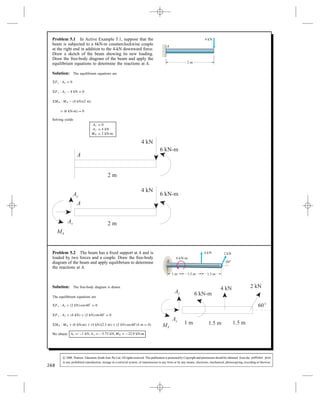
  • 1. Problem 5.1 In Active Example 5.1, suppose that the beam is subjected to a 6kN-m counterclockwise couple at the right end in addition to the 4-kN downward force. Draw a sketch of the beam showing its new loading. Draw the free-body diagram of the beam and apply the equilibrium equations to determine the reactions at A. 4 kN 2 m A Solution: The equilibrium equations are Fx : Ax D 0 Fy : Ay 4 kN D 0 MA : MA 4 kN 2 m C 6 kN-m D 0 Solving yields Ax D 0 Ay D 4 kN MA D 2 kN-m Problem 5.2 The beam has a fixed support at A and is loaded by two forces and a couple. Draw the free-body diagram of the beam and apply equilibrium to determine the reactions at A. 2 kN4 kN 60ЊA 6 kN-m 1.5 m1.5 m1 m Solution: The free-body diagram is drawn. The equilibrium equations are Fx : Ax C 2 kN cos 60° D 0 Fy : Ay C 4 kN C 2 kN sin 60° D 0 MA : MA C 6 kN-m C 4 kN 2.5 m C 2 kN sin 60° 4 m D 0 We obtain: Ax D 1 kN, Ay D 5.73 kN, MA D 22.9 kN-m 268 c 2008 Pearson Education South Asia Pte Ltd. All rights reserved. This publication is protected by Copyright and permission should be obtained from the publisher prior to any prohibited reproduction, storage in a retrieval system, or transmission in any form or by any means, electronic, mechanical, photocopying, recording or likewise.
  • 2. Problem 5.3 The beam is subjected to a load F D 400 N and is supported by the rope and the smooth surfaces at A and B. (a) Draw the free-body diagram of the beam. (b) What are the magnitudes of the reactions at A and B? F 30°45° A B 1.2 m 1.5 m 1 m Solution: FX D 0: A cos 45° B sin 30° D 0 FY D 0: A sin 45° C B cos 30° T 400 N D 0 C MA D 0: 1.2T 2.7 400 C 3.7B cos 30° D 0 Solving, we get A D 271 N B D 383 N T D 124 N x y 1.2 m 1.5 m45° 30°T 1 m B FA Problem 5.4 (a) Draw the free-body diagram of the beam. (b) Determine the tension in the rope and the reactions at B. 5 m 9 m 30Њ 30Њ BA 600 N Solution: Let T be the tension in the rope. The equilibrium equations are: Fx : T sin 30° 600 N sin 30° C Bx D 0 Fy : T cos 30° 600 N cos 30° C By D 0 MB : 600 N cos 30° 9 m T cos 30° 14 m D 0 Solving yields T D 368 N, Bx D 493 N, By D 186 269 N 600 N 9 m5 m c 2008 Pearson Education South Asia Pte Ltd. All rights reserved. This publication is protected by Copyright and permission should be obtained from the publisher prior to any prohibited reproduction, storage in a retrieval system, or transmission in any form or by any means, electronic, mechanical, photocopying, recording or likewise.
  • 3. Problem 5.5 (a) Draw the free-body diagram of the A and B are smooth. (b) Determine the reactions at A and B. 0 A B 30 N 0.25 m 0.35 m Solution: The system is in equilibrium. (a) The free body diagram is shown. (b) The sum of the forces: FX D 0, FY D FA C FB D 0 The sum of the moments about point A: MA D C FB D 0, from which FB D D Substitute into the force balance equation: FA D FB D A B FA FB 300 N 0.25 m 0.35 m 270 300 N drill press, assuming that the surfaces at 300 0.25 300 0.6 75 0.6 125 N 300 175 N c 2008 Pearson Education South Asia Pte Ltd. All rights reserved. This publication is protected by Copyright and permission should be obtained from the publisher prior to any prohibited reproduction, storage in a retrieval system, or transmission in any form or by any means, electronic, mechanical, photocopying, recording or likewise.
  • 4. Problem 5.6 The masses of the person and the diving board are 54 kg and 36 kg, respectively. Assume that they are in equilibrium. (a) Draw the free-body diagram of the diving board. (b) Determine the reactions at the supports A and B. WP A B WD 1.2 m 2.4 m 4.6 m Solution: (a) (b) FX D 0: AX D 0 FY D 0: AY C BY 54 9.81 36 9.81 D 0 MA D 0: 1.2BY 2.4 36 9.81 4.6 54 9.81 D 0 Solving: AX D 0 N AY D 1.85 kN BY D 2.74 kN AY AX BY WPWD 1.2 m 2.4 m 4.6 m Problem 5.7 The ironing board has supports at A and B that can be modeled as roller supports. (a) Draw the free-body diagram of the ironing board. (b) Determine the reactions at A and B. y x A B 50 N 15 N 0.3 m 0.25 m 0.5 m Solution: The system is in equilibrium. (a) The free-body diagram is shown. (b) The sums of the forces are: FX D 0, FY D FA C FB D 0. The sum of the moments about A is MA D FB D 0, from which FB D 43.25 D Substitute into the force balance equation: FA D FB D A B y x FA FB 50 N 0.3 m 0.25 m 0.5 m 15 N 50 N 15 N 271 50 15 0.3 0.55 50 1.05 15 0.3 144.2 N 79.2 N65 c 2008 Pearson Education South Asia Pte Ltd. All rights reserved. This publication is protected by Copyright and permission should be obtained from the publisher prior to any prohibited reproduction, storage in a retrieval system, or transmission in any form or by any means, electronic, mechanical, photocopying, recording or likewise.
  • 5. Problem 5.8 The distance x D 9 m. (a) Draw the free-body diagram of the beam. (b) Determine the reactions at the supports. 10 kN B A x 6 m Solution: (a) The FBD (b) The equilibrium equations Fx : Ax D 0 Fy : Ay C By 10 kN D 0 MA : By 6 m 10 kN 9 m D 0 Solving we find Ax D 0, Ay D 5 kN, By D 15 kN 10 kN 6 m Ax Ay By x = 9 m Problem 5.9 In Example 5.2, suppose that the 200-N downward force and the 300 N-m counterclockwise couple change places; the 200-N downward force acts at the right end of the horizontal bar, and the 300 N-m counterclockwise couple acts on the horizontal bar 2 to the right of the support A. Draw a sketch of the object showing the new loading. Draw the free-body diagram of the object and apply the equilibrium equations to determine the reactions at A. 2 m 2 m 2 m 300 - 2 100 N 200 N A 30 N m m Solution: The sketch and free-body diagram are shown. The equilibrium equations are Fx : Ax C 100 N cos 30° D 0 Fy : Ay C 100 N sin 30° 200 ND 0 MA : MA C 300 N-m C 100 N sin 30° 4 m 100 N cos 30° 2 m 200 N 6 m D 0 We obtain Ax D 86.6 N Ay D 150 N MA D 873 - 272 m N m 2 m2 m 2 m 100 N 200 N300 N-m 2 m 300 N-m 2 m2 m 2 m 100 N 200 N2 m c 2008 Pearson Education South Asia Pte Ltd. All rights reserved. This publication is protected by Copyright and permission should be obtained from the publisher prior to any prohibited reproduction, storage in a retrieval system, or transmission in any form or by any means, electronic, mechanical, photocopying, recording or likewise.
  • 6. Problem 5.10 (a) Draw the free-body diagram of the beam. (b) Determine the reactions at the supports. 100 N 400 N BA 900 N-m 3 m 4 m 3 m 4 m Solution: (a) Both supports are roller supports. The free body diagram is shown. (b) The sum of the forces: FX D 0, and FY D FA C FB C 100 400 D 0. The sum of the moments about A is MA D 3 100 C 900 7 400 C 11FB D 0. From which FB D 2200 11 D 200 N Substitute into the force balance equation to obtain FA D 300 FB D 100 3 m 3 m 3 m 3 m 900 900 N-m BA 4 m 4 4 4 m FA FB 400 400 N 100 N 100 N m m N-m N Problem 5.11 The person exerts 20-N forces on the pliers. The free-body diagram of one part of the pliers is shown. Notice that the pin at C connecting the two parts of the pliers behaves like a pin support. Determine the reactions at C and the force B exerted on the pliers by the bolt. 20 N 20 N 20 N C 50 mm 45Њ 80 mm 25 mm C Cy Cx B Solution: The equilibrium equations MC :B 25 mm 20 N cos 45° 80 mm 20 N sin 45° 50 mm D 0 Fx :Cx 20 N sin 45° D 0 Fy :Cy B 20 N cos 45° D 0 Solving: B D 73.5 N, Cx D 14.14 N, Cy D 87.7 N 273 N c 2008 Pearson Education South Asia Pte Ltd. All rights reserved. This publication is protected by Copyright and permission should be obtained from the publisher prior to any prohibited reproduction, storage in a retrieval system, or transmission in any form or by any means, electronic, mechanical, photocopying, recording or likewise.
  • 7. Problem 5.12 (a) Draw the free-body diagram of the beam. (b) Determine the reactions at the pin support A. 30Њ A B2 kN-m 8 kN 8 kN 600 mm 500 mm 600 mm 600 mm Solution: (a) The FBD (b) The equilibrium equations MA : 8 kN 0.6 m C 8 kN 1.1 m 2 kNm B cos 30° 2.3 m D 0 Fx :Ax B sin 30° D 0 Fy :Ay 8 kN C 8 kN B cos 30° D 0 Solving Ax D 0.502 kN, Ay D 0.870 kN, B D 1.004 kN 8 kN 8 kN 2 kN-m Ax Ay B30° Problem 5.13 (a) Draw the free-body diagram of the beam. (b) Determine the reactions at the supports. A y 6 m 8 m 12 m B x 40 kN Solution: (a) The FBD (b) The equilibrium equations MB : 40 kN 4 m C A 6 m D 0 Fx : A C Bx D 0 Fy : 40 kN C By D 0 Solving we find A D Bx D 26.7 kN, By D 40 kN A By Bx 40 kN 274 c 2008 Pearson Education South Asia Pte Ltd. All rights reserved. This publication is protected by Copyright and permission should be obtained from the publisher prior to any prohibited reproduction, storage in a retrieval system, or transmission in any form or by any means, electronic, mechanical, photocopying, recording or likewise.
  • 8. Problem 5.14 (a) Draw the free-body diagram of the beam. (b) If F D 4 kN, what are the reactions at A and B? A 2 kN-m B F 0.2 m 0.4 m0.3 m 0.3 m 0.2 m Solution: (a) The free-body diagram (b) The equilibrium equations MA : 2 kN-m 4 kN 0.2 m C B 1.0 m D 0 Fx : Ax 4 kN D 0 Fy : Ay C B D 0 Solving: Ax D 4 kN, Ay D 2.8 kN, B D 2.8 kN Ax Ay B 2 kN-m F = 4 kN 275 c 2008 Pearson Education South Asia Pte Ltd. All rights reserved. This publication is protected by Copyright and permission should be obtained from the publisher prior to any prohibited reproduction, storage in a retrieval system, or transmission in any form or by any means, electronic, mechanical, photocopying, recording or likewise.
  • 9. Problem 5.15 In Example 5.3, suppose that the attach- ment point for the suspended mass is moved toward point B such that the horizontal distance from A to the attachment point increases from 2 m to 3 m. Draw a sketch of the beam AB showing the new geometry. Draw the free-body diagram of the beam and apply the equilibrium equations to determine the reactions at A to B. 2 m A B 3 m 2 m Solution: From Example 5.3, we know that the mass of the suspended object is 2-Mg. The sketch and free-body diagram are shown. The equilibrium equations are Fx : Ax C Bx D 0 Fy : By 2000 kg 9.81 m/s2 D 0 MB : Ax 3 m C 2000 kg 9.81 m/s2 1 m D 0 We obtain Ax D 6.54 kN Bx D 6.54 kN By D 19.6 kN 276 c 2008 Pearson Education South Asia Pte Ltd. All rights reserved. This publication is protected by Copyright and permission should be obtained from the publisher prior to any prohibited reproduction, storage in a retrieval system, or transmission in any form or by any means, electronic, mechanical, photocopying, recording or likewise.
  • 10. Problem 5.16 A person doing push-ups pauses in the position shown. His 0 weight W acts at the point shown. The dimensions a = 375 mm, b = 1000 mm, and c = 400 floor on each of his hands and on each of his feet. W a b c Solution: The free-body diagram is shown. The equilibrium equations are Fy : 2H C 2F D 0 MH : Wa C 2F a C b 0 We find that H D , F D Thus Problem 5.17 The hydraulic piston AB exertsa2000 N force on the ladder at B in the direction parallel to the piston. Determine the weight of the ladder and the reac- tions at C. A B C W 2 m 1 m 2 m 1 m Solution: The free-body diagram of the ladder is shown. The angle between the piston AB and the horizontal is ˛ D tan 1 1/2 D 26.6° The equilibrium equations are Fx : Cx C cos ˛ D 0 Fy : Cy C sin ˛ W D 0 MC : W cos ˛ sin ˛ D 0 Solving yields Cx D , Cy D , W D 277 80 N mm. Determine the normal force exerted by the 800 N 290.9 N 109.1 N 290.9 N on each hand 109.1 N on each foot 8 0 N 2000 N 2000 N 2 m 2000 N 1 m 2000 N 1 m 1788.3 N 446.4 N 1341.9 N 2000 N 0 c 2008 Pearson Education South Asia Pte Ltd. All rights reserved. This publication is protected by Copyright and permission should be obtained from the publisher prior to any prohibited reproduction, storage in a retrieval system, or transmission in any form or by any means, electronic, mechanical, photocopying, recording or likewise.
  • 11. Problem 5.18 Draw the free-body diagram of the structure by isolating it from its supports at A and E. Determine the reactions at A and E. C D BA 100 N E 400 N 200 N-m 2 m 1 m 1 m 2 m 2 m 2 m Solution: The free-body diagram is shown. The equilibrium equations are Fx : Ax C 100 N D 0 Fy : Ay 400 N C Ey D 0 MA : 100 N 1 m 400 N 6 m 200 N-m C Ey 4 m D 0 Solving yields Ax D 100 N Ay D 225 N Ey D 625 Problem 5.19 (a) Draw the free-body diagram of the beam. (b) Determine the tension in the cable and the reactions at A. A 800 N B C30° 0.15 m 0.15 m 0.15 m Solution: (a) The FBD (b) The equilibrium equations MA : 800 N 0.3 m C T C T sin 30° D 0 Fx :Ax T cos 30° D 0 Fy :Ay C T C T sin 30° 800 ND 0 Solving: Ax D 554 N, Ay D 160 , T D 640 Ax Ay T T 800 30° N 278 100 N 400 N 200 N-m N 0. 5 m 0.45 m N N 1 c 2008 Pearson Education South Asia Pte Ltd. All rights reserved. This publication is protected by Copyright and permission should be obtained from the publisher prior to any prohibited reproduction, storage in a retrieval system, or transmission in any form or by any means, electronic, mechanical, photocopying, recording or likewise.
  • 12. Problem 5.20 The unstretched length of the spring CD is 350 mm. Suppose that you want the lever ABC to exert a 120-N normal force on the smooth surface at A. Determine the necessary value of the spring constant k and the resulting reactions at B. 20Њ B A C k D 450 mm 180 mm 300 mm 330 mm 230 mm Solution: We have F D k 0.23 m 2 C 0.3 m2 0.35 m A D 120 N MB : 30 p 1429 F 0.45 m C A cos 20° 0.18 m C A sin 20° 0.33 m D 0 Fx :A cos 20° C Bx C 30 p 1429 F D 0 Fy : A sin 20° C By 23 p 1429 F D 0 Solving we find: k D 3380 N/m, Bx D 188 N, By D 98.7 N A F 20° 30 23 Bx By 279 c 2008 Pearson Education South Asia Pte Ltd. All rights reserved. This publication is protected by Copyright and permission should be obtained from the publisher prior to any prohibited reproduction, storage in a retrieval system, or transmission in any form or by any means, electronic, mechanical, photocopying, recording or likewise.
  • 13. Problem 5.21 The mobile is in equilibrium. The fish B weighs 2 7 . Determine the weights of the fish A, C, and D. (The weights of the crossbars are negligible.) m A C D B 0.24 0.06 m 0.12 m 0.04 m 0.14 m 0.04 m Solution: Denote the reactions at the supports by FAB, FCD, and FBCD as shown. Start with the crossbar supporting the weights C and D. The sum of the forces is FY D C D C FCD D 0, from which FCD D C C D. For the cross bar supporting the weight B, the sum of the forces is FY D B C FBCD FCD D 0, from which, substituting, FBCD D B C C C D. For the crossbar supporting C and D, the sum of the moments about the support is MCD D D C C D 0, from which D D C . For the crossbar supporting B, the sum of the moments is MBCD D FCD B D 0, from which, substituting from above FCD D B D C C D D C C C D C , or C D B/ D , and D D C/ D . The sum of the moments about the crossbar supporting A is MAB D A FBCD D 0, from which, substituting from above, A D B C C C D D 2. 7 C C 4 D 9 A B CD FCD FBCD FCD FBCD FAB 0.14 m 0.04 m 0.12 m 0.04 m 0.24 m 0.06 m 280 . N 0 . 14 0.04 0.04 0.14 0.12 0.04 0.04 0.12 0.04 0.14 0.14 0.18 0.14 0.54 0.7 N 0.04 0.14 0.2 N 0.24 0.06 0.06 0.24 0 . 7 0 . 2 0. N c 2008 Pearson Education South Asia Pte Ltd. All rights reserved. This publication is protected by Copyright and permission should be obtained from the publisher prior to any prohibited reproduction, storage in a retrieval system, or transmission in any form or by any means, electronic, mechanical, photocopying, recording or likewise.
  • 14. Problem 5.22 The car’s wheelbase (the distance between the wheels) is 2.82 m. The mass of the car is 1760 kg and its weight acts at the point x D 2.00 m, y D 0.68 m. If the angle ˛ D 15°, what is the total normal force exerted on the two rear tires by the sloped ramp? y x α Solution: Split W into components: W cos ˛ acts ? to the incline W sin ˛ acts parallel to the incline FX: f W sin ˛ D 0 FY: NR C NF W cos ˛ D 0 MR: 2 W cos ˛ C 0.68 W sin ˛ C 2.82NF D 0 Solving: NR D 5930 N, NF D 10750 N 0.68 m f NR NF α α y 2.82 m x W R 2 m W = (1760X9.81) N α = 15° Problem 5.23 The link AB exerts a force on the bucket of the excavator at A that is parallel to the link. The weight W = 6000 N. Draw the free-body diagram of the bucket and determine the reactions at C. (The connection at C is equivalent to a pin support of the bucket.) W C D A B 28 cm 32 cm 8 cm 16 cm 16 cm Solution: The free-body diagram is shown. The angle between the link AB and the horizontal is ˛ D tan 1 / D 40.6° The equilibrium equations are Fx : Cx C TAB cos ˛ D 0 Fy : Cy C TAB sin ˛ D 0 MC : TAB cos ˛ TAB sin ˛ D 0 Solving yields TAB D , Cx D , Cy D 281 6000 N 24 28 6000 N 6000 N 16 cm 8 cm 32 cm 3568 N 2708 N 3676 N c 2008 Pearson Education South Asia Pte Ltd. All rights reserved. This publication is protected by Copyright and permission should be obtained from the publisher prior to any prohibited reproduction, storage in a retrieval system, or transmission in any form or by any means, electronic, mechanical, photocopying, recording or likewise.
  • 15. Problem 5.24 The 72.5 N chain saw is subjected to the loads at A by the log it cuts. Determine the reactions R, Bx, and By that must be applied by the person using the saw to hold it in equilibrium. y x R By Bx 60° A 0.03 m 25 N 50 N 0.26 m 0.04 m 0.12 m 72.5 N 0.14 m Solution: The sum of the forces are FX D 5 C BX R cos 60° D 0. FY D C BY R sin 60° D 0. The sum of the moments about the origin is MO D R cos 60° C BY . From which 0.14R cos 60°C BY 16 65 D 0. Collecting equations and reducing to 3 equations in 3 unknowns: BX C 0BY 0.5R D 0BX C BY 0.866R D .5 0BX C BY C R D 16.65. Solving: BX D , BY D , and R D Problem 5.25 The mass of the trailer is 2.2 Mg (mega- grams). The distances a D 2.5 m and b D 5.5 m. The truck is stationary, and the wheels of the trailer can turn freely, which means that the road exerts no horizontal force on them. The hitch at B can be modeled as a pin support. (a) Draw the free-body diagram of the trailer. (b) Determine the total normal force exerted on the rear tires at A and the reactions exerted on the trailer at the pin support B. a b W A B Solution: (a) The free body diagram is shown. (b) The sum of forces: FX D BX D 0. FY D FA W C FB D 0. The sum of the moments about A: MA D aW C a C b FB D 0, from which FB D aW a C b D 2.5 2.2 ð 103 9.81 2.5 C 5.5 D 6.744 kN Substitute into the force equation: FA D W FB D 14.838 kN a b A W B FA FB BX 282 2 50 72.5 0.14 0.16 0.04 72.5 0.26 50 D 025 0.03 0.16 . 25 22 0.16 0.07 56.286 N 76.687 N 62.572 N c 2008 Pearson Education South Asia Pte Ltd. All rights reserved. This publication is protected by Copyright and permission should be obtained from the publisher prior to any prohibited reproduction, storage in a retrieval system, or transmission in any form or by any means, electronic, mechanical, photocopying, recording or likewise.
  • 16. Problem 5.26 The total weight of the wheelbarrow and its load is W = 500 N. (a) What is the magnitude of the upward force F necessary to lift the support at A off the ground? (b) What is the magnitude of the downward force necessary to raise the wheel off the ground? B W A F 1 m 0.3 m 0.35 m Solution: The free-body diagram is shown. The equilibrium equations are Fy : A C B C F W D 0 MA : B W F D 0 (a) Set A D 0 and solve. We find that F D (b) Set B D 0 and solve. We find that F D So we have a , b . 283 0.65 m 0.3 m 1 m 106 N 150 N 106 N 150 N c 2008 Pearson Education South Asia Pte Ltd. All rights reserved. This publication is protected by Copyright and permission should be obtained from the publisher prior to any prohibited reproduction, storage in a retrieval system, or transmission in any form or by any means, electronic, mechanical, photocopying, recording or likewise.
  • 17. Problem 5.27 The airplane’s weight is WD 2 00 N. Its brakes keep the rear wheels locked. The front (nose) wheel can turn freely, and so the ground exerts no hori- zontal force on it. The force T exerted by the airplane’s propeller is horizontal. (a) Draw the free-body diagram of the airplane. Deter- mine the reaction exerted on the nose wheel and the total normal reaction on the rear wheels (b) when T D 0, (c) when T D W T BA 1.2 m 1.5 m 0.6 m Solution: (a) The free body diagram is shown. (b) The sum of the forces: FX D BX D 0 FY D AY W C BY D 0. The sum of the moments about A is MA D W C BY D 0, from which BY D W D Substitute from the force balance equation: AY D W BY D (c) The sum of the forces: FX D C BX D 0, from which BX D FY D AY W C BY D 0. The sum of the moments about A: MA D W C BY D 0, from which BY D . Substitute into the force balance equation to obtain: AY D A W B BX BY AY 1.2 m 1.5 m 0.6 m 284 1 0 1250 N. 1.5 2.1 1.5 2.1 8571.4 N 3248.6 N 1250 1250 1250 1.2 1.5 2.1 7857.1 N 4142.9 N N c 2008 Pearson Education South Asia Pte Ltd. All rights reserved. This publication is protected by Copyright and permission should be obtained from the publisher prior to any prohibited reproduction, storage in a retrieval system, or transmission in any form or by any means, electronic, mechanical, photocopying, recording or likewise.
  • 18. Problem 5.28 A safety engineer establishing limits on the load that can be carried by a forklift analyzes the situation shown. The dimensions are a = 1.25 m, b = 0.5 m and c = 1.40 m. The combined weight of the forklift and operator is WF = 2 kN. As the weight WL supported by the forklift increases, the normal force exerted on the floor by the rear wheels at B decreases. The forklift is on the verge of tipping forward when the normal force at B is zero. Determine the value of WL that will cause this condition. a b c WF BA WL Solution: The equilibrium equations and the special condition for this problem are Fy : A C B WL 2000 N D 0 MA : WLa WFb C Bc D 0 B D 0 We obtain WL D 285 800 N c 2008 Pearson Education South Asia Pte Ltd. All rights reserved. This publication is protected by Copyright and permission should be obtained from the publisher prior to any prohibited reproduction, storage in a retrieval system, or transmission in any form or by any means, electronic, mechanical, photocopying, recording or likewise.
  • 19. Problem 5.29 Paleontologists speculate that the ste- gosaur could stand on its hind limbs for short periods to feed. Based on the free-body diagram shown and assuming that m D 2000 kg, determine the magnitudes of the forces B and C exerted by the ligament–muscle brace and vertebral column, and determine the angle ˛. mg B 22° α C 160 mm 580 mm 415 mm 790 mmSolution: Take the origin to be at the point of application of the force C. The position vectors of the points of application of the forces B and W are: rB D 415i C 160j (mm), rW D 790i C 580j (mm). The forces are C D C i cos 90° ˛ C j sin 90° ˛ D C i sin ˛ C j cos ˛ . B D B i cos 270° 22° C j sin 270° 22° D B 0.3746i 0.9272j . W D 2 9.81 j D 19.62j (kN). The moments about C, MC D i j k 415 160 0 0.3746B 0.9272B 0 C i j k 790 580 0 0 19.62 0 D 0 D 444.72B 15499.8 D 0, from which B D 15499.8 444.72 D 34.85 kN. The sums of the forces: FX D C sin ˛ 0.3746B i D 0, from which C sin ˛ D 13.06 kN. FY D C cos ˛ 0.9272B 19.62 j D 0, from which C cos ˛ D 51.93 kN. The angle ˛ is ˛ D tan 1 13.06 51.93 D 14.1°. The magnitude of C, C D p 13.062 C 51.932 D 53.55 kN 286 c 2008 Pearson Education South Asia Pte Ltd. All rights reserved. This publication is protected by Copyright and permission should be obtained from the publisher prior to any prohibited reproduction, storage in a retrieval system, or transmission in any form or by any means, electronic, mechanical, photocopying, recording or likewise.
  • 20. Problem 5.30 The weight of the fan is W D base has four equally spaced legs of length b D Each leg has a pad near the end that contacts the floor and supports the fan. The height hD blade exerts a thrust T D is exerted on the two legs at A? h b T W Side View A B Top View T Solution: The free-body diagram is shown. The equilibrium equations are Fy : A C B W D 0 MB : W b p 2 A 2b p 2 Th D 0 We obtain A D Problem 5.31 The weight of the fan is WD base has four equally spaced legs of length b D Each leg has a pad near the end that contacts the floor and supports the fan. The height h D T of the fan increases, the normal force supported by the two legs at A decreases. When the normal force at A is zero, the fan is on the verge of tipping over. Determine the value of T that will cause this condition. h b T W Side View A B Top View T Solution: The free-body diagram is shown. The equilibrium equations are Fy : A C B W D 0 MB : W b p 2 A 2b p 2 Th D 0 We set A D 0 and solve to obtain T D 287 100 N. Its 0.3 m. 0.9 m. If the fan’s 10 N, what total normal force 28.8 N 100 N. Its 0 .3 m. 0.9 m. As the thrust 23.6 N c 2008 Pearson Education South Asia Pte Ltd. All rights reserved. This publication is protected by Copyright and permission should be obtained from the publisher prior to any prohibited reproduction, storage in a retrieval system, or transmission in any form or by any means, electronic, mechanical, photocopying, recording or likewise.
  • 21. Problem 5.32 In a measure to decrease costs, the manufacturer of the fan described in Problem 5.31 proposes to support the fan with three equally spaced legs instead of four. An engineer is assigned to analyze the safety implications of the change. The weight of the fan decreases to W D . The dimensions b and h are unchanged. What thrust T will cause the fan to be on the verge of tipping over in this case? Compare your answer to the answer to Problem 5.31. b T Solution: The free-body diagram is shown. The equilibrium equations are Fy : A C B W D 0 MB : Wb cos 60° A b C b cos 60° Th D 0 We set A D 0 and solve to obtain T D This configuration is less stable than the one in Problem 5.31 using four legs. Problem 5.33 A force F D 400 N acts on the bracket. What are the reactions at A and B? B A F 320 mm 80 mm Solution: The joint A is a pinned joint; B is a roller joint. The pinned joint has two reaction forces AX, AY. The roller joint has one reaction force BX. The sum of the forces is FX D AX C BX D 0, FY D AY F D 0, from which AY D F D 400 N. The sum of the moments about A is MA D 0.08BX 0.320F D 0, from which BX D 0.320 400 0.08 D 1600 N. Substitute into the sum of forces equation to obtain: AX D BX D 1600 N AX BX AY 320 mm 80 mm F 288 59 N 15.8 N c 2008 Pearson Education South Asia Pte Ltd. All rights reserved. This publication is protected by Copyright and permission should be obtained from the publisher prior to any prohibited reproduction, storage in a retrieval system, or transmission in any form or by any means, electronic, mechanical, photocopying, recording or likewise.
  • 22. Problem 5.34 The sign’s weight WS D the point shown. The 50 N weight of bar AD acts at the midpoint of the bar. Determine the tension in the cable AE and the reactions at D. Ws B A C D E Њ 30Њ 20 0.22 m 0.6 m 0.22 m 0.66 m Solution: Treat the bar AD and sign as one single object. Let TAE be the tension in the cable. The equilibium equations are Fx : TAE cos 20° C Dx D 0 Fy : TAE sin 20° C Dy Ws D 0 MD : TAE cos ° tan 30° TAE sin 20° C C D 0 Solving yields TAE D Dx D Dy D 289 160 N acts at 50 N = 160 N 50 N 1.04 m20 1.04 m 160 N 0.66 m 50 N 0.52 m 143 N 134.4 N 161.1 N c 2008 Pearson Education South Asia Pte Ltd. All rights reserved. This publication is protected by Copyright and permission should be obtained from the publisher prior to any prohibited reproduction, storage in a retrieval system, or transmission in any form or by any means, electronic, mechanical, photocopying, recording or likewise.
  • 23. Problem 5.35 The device shown, called a swape or shadoof, helps a person lift a heavy load. (Devices of this kind were used in Egypt at least as early as 1550 B.C. and are still in use in various parts of the world.) The dimensions a D 3.6 m and b D 1.2 m. The mass of the bar and counterweight is 90 kg, and their weight W acts at the point shown. The mass of the load being lifted is 45 kg. Determine the vertical force the person must exert to support the stationary load (a) when the load is just above the ground (the position shown); (b) when the load is 1 m above the ground. Assume that the rope remains vertical. W 25° b a Solution: MO : 441 N F 3.6 m cos  883 N 1.2 m cos  D 0 Solving we find F D 147.2 N Notice that the angle  is not a part of this answer therefore (a) F D 147.2 N (b) F D 147.2 N F Oy Ox 441 N 883 N θ Problem 5.36 This structure, called a truss, has a pin support at A and a roller support at B and is loaded by two forces. Determine the reactions at the supports. Strategy: Draw a free-body diagram, treating the entire truss as a single object. b b b b 4 kN 2 kN A 45° B b 30° Solution: MA : 4 kN p 2b 2 kN cos 30° 3 b C 2 kN sin 30° b C B 4 b D 0 Fx : Ax C 4 kN sin 45° 2 kN sin 30° D 0 Fy : Ay 4 kN cos 45° 2 kN cos 30° C B D 0 Solving: Ax D 1.828 kN, Ay D 2.10 kN, B D 2.46 kN B 45° 30° Ay Ax 4 kN 2 kN 290 c 2008 Pearson Education South Asia Pte Ltd. All rights reserved. This publication is protected by Copyright and permission should be obtained from the publisher prior to any prohibited reproduction, storage in a retrieval system, or transmission in any form or by any means, electronic, mechanical, photocopying, recording or likewise.
  • 24. Problem 5.37 An Olympic gymnast is stationary in the “iron cross” position. The weight of his left arm and the weight of his body not including his arms are shown. The distances are aD b D and cD . Treat his shoulder S as a fixed support, and determine the magnitudes of the reactions at his shoulder. That is, determine the force and couple his shoulder must support. a b c S 720 N 40 N Solution: The shoulder as a built-in joint has two-force and couple reactions. The left hand must support the weight of the left arm and half the weight of the body: FH D 2 C D . The sum of the forces on the left arm is the weight of his left arm and the vertical reaction at the shoulder and hand: FX D SX D 0. FY D FH SY D 0, from which SY D FH D . The sum of the moments about the shoulder is MS D M C b C c FH b D 0, where M is the couple reaction at the shoulder. Thus M D b b C c FH D SX SY M FH FH FH b c 40 N 40 N 720 N 40 N 291 0.225 m 0.325 m 720 40 400 N 4 0 40 360 N 4 0 40 211 N-m c 2008 Pearson Education South Asia Pte Ltd. All rights reserved. This publication is protected by Copyright and permission should be obtained from the publisher prior to any prohibited reproduction, storage in a retrieval system, or transmission in any form or by any means, electronic, mechanical, photocopying, recording or likewise.
  • 25. Problem 5.38 Determine the reactions at A. 6 m 3 m 300 N 200 5 800 N-m 200 N A m N Solution: The built-in support at A is a two-force and couple reac- tion support. The sum of the forces for the system is FX D AX C 200 D 0, from which AX D 200 N FY D AY C 300 200 D 0, from which AY D 100 N The sum of the moments about A: M D 6 300 C 5 200 800 C MA D 0, from which MA D 1600 which is the couple at A. 6 m 3 m 5 m 200 N 300 N 200 N 800 N-m MA AX AY 292 N-m c 2008 Pearson Education South Asia Pte Ltd. All rights reserved. This publication is protected by Copyright and permission should be obtained from the publisher prior to any prohibited reproduction, storage in a retrieval system, or transmission in any form or by any means, electronic, mechanical, photocopying, recording or likewise.
  • 26. Problem 5.39 The car’s brakes keep the rear wheels locked, and the front wheels are free to turn. Determine the forces exerted on the front and rear wheels by the road when the car is parked (a) on an up slope with ˛ D 15°; (b) on a down slope with ˛ D 15°. 00 y 0.5 m x α 0.9 m 1.75 m 165 N Solution: The rear wheels are two force reaction support, and the front wheels are a one force reaction support. Denote the rear wheels by A and the front wheels by B, and define the reactions as being parallel to and normal to the road. The sum of forces: FX D AX ° D 0 , from which AX D . FY D AY 00 cos 15° C BY D 0. Since the mass center of the vehicle is displaced above the point A, a component of the weight (0.5Wsin ˛) produces a positive moment about A, whereas the other component ( Wcos ˛) produces a negative moment about A. The sum of the moments about A: MA D ° C ° C BY D 0, from which BY D C D . Substitute into the sum of forces equation to obtain AY D (b) For the car parked down-slope the sum of the forces is FX D AX C sin 15° D 0, from which AX D FY D AY ° C BY D 0. The component ( W sin ˛) now produces a negative moment about A. The sum of the moments about A is MA D cos 15° sin 15° C BY D 0, from which BY D D . Substitute into the sum of forces equation to obtain AY D 9 AX AY BY 00 α 0.5 m 165 N 1.75 m 0.9 m 293 16,500 sin 15 4270.5 N 16,5 0.9 0.9 16,500 cos 15 0.5 16,500 sin 15 2.65 12,209 2.65 4607.1 N 11330 N 16,500 4270.5 N 16,500cos 15 0.5 16,500 0.9 16,500 0.5 2.65 16479 2.65 6218.6 N 719.2 N c 2008 Pearson Education South Asia Pte Ltd. All rights reserved. This publication is protected by Copyright and permission should be obtained from the publisher prior to any prohibited reproduction, storage in a retrieval system, or transmission in any form or by any means, electronic, mechanical, photocopying, recording or likewise.
  • 27. Problem 5.40 The length of the bar is L D 4 m. Its weight W D 60 N acts at the midpoint of the bar. The floor and wall are smooth. The spring is unstretched when the angle ˛ = 0. If the bar is in equilibrium when ˛ D 40°, what is the spring constant k? L k α Solution: The free-body diagram is shown. The stretch in the spring is L L cos ˛, so the upward force exerted on the bar by the spring is F D kL 1 cos ˛ . Let N and R be the normal forces exerted by the floor and the wall, respectively. The equilibrium equations for the bar are Fx : R D 0 Fy : F C N W D 0 Mbottom : W L 2 sin ˛ RL cos ˛ FL sin ˛ D 0 Because R D 0, the moment equation can be solved for the force exerted by the spring. F D 0.5W D 30 N D kL 1 cos ˛ Solving yields k D 32 1 / 294 . N m c 2008 Pearson Education South Asia Pte Ltd. All rights reserved. This publication is protected by Copyright and permission should be obtained from the publisher prior to any prohibited reproduction, storage in a retrieval system, or transmission in any form or by any means, electronic, mechanical, photocopying, recording or likewise.
  • 28. Problem 5.41 The weight W of the bar acts at its midpoint. The floor and wall are smooth. The spring is unstretched when the angle ˛ D 0. Determine the angle ˛ at which the bar is in equilibrium in terms of W, k, and L. L k α Solution: The free-body diagram is shown. The stretch in the spring is L L cos ˛, so the upward force exerted on the bar by the spring is F D kL 1 cos ˛ . Let N and R be the normal forces exerted by the floor and the wall, respectively. The equilibrium equations for the bar are Fx : R D 0 Fy : F C N W D 0 Mbottom : W L 2 sin ˛ RL cos ˛ FL sin ˛ D 0 Because R D 0, the moment equation can be solved for the force exerted by the spring. F D W 2 D kL 1 cos ˛ Solving yields ˛ D cos 1 1 W 2L 295 c 2008 Pearson Education South Asia Pte Ltd. All rights reserved. This publication is protected by Copyright and permission should be obtained from the publisher prior to any prohibited reproduction, storage in a retrieval system, or transmission in any form or by any means, electronic, mechanical, photocopying, recording or likewise.
  • 29. Problem 5.42 The plate is supported by a pin in a smooth slot at B. What are the reactions at the supports? B 2 kN-m 2 m 6 kN-m 60° A Solution: The pinned support is a two force reaction support. The smooth pin is a roller support, with a one force reaction. The reaction at B forms an angle of 90° C 60° D 150° with the positive x axis. The sum of the forces: FX D AX C B cos 150° D 0 FY D AY C B sin 150° D 0 The sum of the moments about B is MB D 2AY C 2 6 D 0, from which AY D 4 2 D 2 kN. Substitute into the force equations to obtain B D AY sin 150° D 4 kN, and AX D B cos 150° D 3.464 kN. The horizontal and vertical reactions at B are BX D 4 cos 150° D 3.464 kN, and BY D 4 sin 150° D 2 kN. B 2 kN-m 2 m 6 kN-m 60°A 2 kN-m 6 kN-m AX AY 2 m B 150° 296 c 2008 Pearson Education South Asia Pte Ltd. All rights reserved. This publication is protected by Copyright and permission should be obtained from the publisher prior to any prohibited reproduction, storage in a retrieval system, or transmission in any form or by any means, electronic, mechanical, photocopying, recording or likewise.
  • 30. Problem 5.43 Determine the reactions at the fixed support A. 30 N 40 N 150 N-m 3 m A y x 3 m 6 45Њ m Solution: The free-body diagram is shown. The equilibrium equations are Fx : Ax C 40 N cos 45° D 0 Fy : Ay C 30 N C 40 N sin 45° D 0 MA : MA C 30 N 3 m C 40 N sin 45° 6 m C 150 N-m D 0 Solving yields Ax D 28.3 N, Ay D 58.3 N, MA D 410 - . Problem 5.44 Suppose the you want to represent the two forces and couple acting on the beam in Problem 5.43 by an equivalent force F as shown. (a) Determine F and the distance D at which its line of action crosses the x axis. (b) Assume that F is the only load acting on the beam and determine the reactions at the fixed support A. Compare your answers to answers to Problem 5.43. F y x D A Solution: The free-body diagram is shown. (a) To be equivalnet, F must equal the sum of the two forces: F D 30 N j C 40 N cos 45°i C sin 45°j F D 28.3i C 58.3j The force F must be placed so that the moment about a point due to F is equal to the moment about the same point due to the two forces and couple. Evaluating the moments about the origin, 58.3 N D D 30 N 3 m C 40 N sin 45° 6 C 150 - The distance D D 7.03 (b) The equilibrium equations are Fx : Ax C 28.3 N D 0 Fy : Ay C 58.3 N D 0 MA : MA C 58.3 7.03 D 0 Solving yields Ax D 28.3 N, Ay D 58.3 N, MA D 410 - . 297 N m 30 N N40 N-m150 3 m 3 m m6 N m N m m N m N m c 2008 Pearson Education South Asia Pte Ltd. All rights reserved. This publication is protected by Copyright and permission should be obtained from the publisher prior to any prohibited reproduction, storage in a retrieval system, or transmission in any form or by any means, electronic, mechanical, photocopying, recording or likewise.
  • 31. Problem 5.45 The bicycle brake on the right is pinned to the bicycle’s frame at A. Determine the force exerted by the brake pad on the wheel rim at B in terms of the cable tension T. T 40 mm 45 mm 40 mm Brake pad Wheel rim 35° A B Solution: From the force balance equation for the cables: the force on the brake mechanism TB in terms of the cable tension T is T 2TB sin 35° D 0, from which TB D T 2 sin 35° D 0.8717T. Take the origin of the system to be at A. The position vector of the point of attachment of B is rB D 45j (mm). The position vector of the point of attachment of the cable is rC D 40i C 85j (mm). The force exerted by the brake pad is B D Bi. The force vector due the cable tension is TB D TB i cos 145° C j sin 145° D TB 0.8192i C 0.5736j . The moment about A is MA D rB ð B C rC ð TB D 0 MA D i j k 0 45 45 B 0 0 C i j k 40 85 85 0.8192 0.5736 0 TB D 0 MA D 45B C 92.576TB k D 0, from which B D 92.576TB 45 D 2.057TB. Substitute the expression for the cable tension: B D 2.057 0.8717 T D 1.793T TB 35° 40 mm 45 mm 40 mm AX AY B 298 c 2008 Pearson Education South Asia Pte Ltd. All rights reserved. This publication is protected by Copyright and permission should be obtained from the publisher prior to any prohibited reproduction, storage in a retrieval system, or transmission in any form or by any means, electronic, mechanical, photocopying, recording or likewise.
  • 32. Problem 5.46 The mass of each of the suspended weights is 80 kg. Determine the reactions at the supports at A and E. A B C D E 200 mm 200 mm 300 mm Solution: From the free body diagram, the equations of equilibrium for the rigid body are Fx D AX C EX D 0, Fy D AY 2 80 9.81 D 0, and MA D 0.3EX 0.2 80 9.81 0.4 80 9.81 D 0. We have three equations in the three components of the support reactions. Solving for the unknowns, we get the values AX D 1570 N, AY D 1570 N, and EX D 1570 N. AY EX AX y x mg mg A E 0.2 m 0.3 m 0.2 m Problem 5.47 The suspended weights in Problem 5.46 are each of mass m. The supports at A and E will each safely support a force of 6 kN magnitude. Based on this criterion, what is the largest safe value of m? Solution: Written with the mass value of 80 kg replaced by the symbol m, the equations of equilibrium from Problem 5.46 are Fx D AX C EX D 0, Fy D AY 2 m 9.81 D 0, and MA D 0.3EX 0.2 m 9.81 0.4 m 9.81 D 0. We also need the relation jAj D A2 X C A2 Y D 6000 N. We have four equations in the three components of the support reactions plus the magnitude of A. This is four equations in four unknowns. Solving for the unknowns, we get the values AX D 4243 N, AY D 4243 N, EX D 4243 N, and m D 216.5 kg. Note: We could have gotten this result by a linear scaling of all of the numbers in Problem 5.46. 299 c 2008 Pearson Education South Asia Pte Ltd. All rights reserved. This publication is protected by Copyright and permission should be obtained from the publisher prior to any prohibited reproduction, storage in a retrieval system, or transmission in any form or by any means, electronic, mechanical, photocopying, recording or likewise.
  • 33. Problem 5.48 The tension in cable BC is 00 . Determine the reactions at the built-in support. 2 m B C A 2 m 500 N-m 1000 N m11 m Solution: The cable does not exert an external force on the system, and can be ignored in determining reactions. The built-in support is a two-force and couple reaction support. The sum of forces: FX D AX D 0. FY D AY D 0, from which AY D 00 . The sum of the moments about A is M D MA D 0, from which MA D 00 AY MA AX 500 N-m 1000 N 1 m Problem 5.49 The tension in cable AB is 2 kN. What are the reactions at C in the two cases? 2 m 1 m C (a) 60° 2 m 1 m A B C (b) 60°A B Solution: First Case: The sum of the forces: FX D CX T cos 60° D 0, from which CX D 2 0.5 D 1 kN FY D CY C T sin 60° C T D 0, from which CY D 1.866 2 D 3.732 kN. The sum of the moments about C is M D MC T sin 60° 3T D 0, from which MC D 3.866 2 D 7.732 kN Second Case: The weight of the beam is ignored, hence there are no external forces on the beam, and the reactions at C are zero. T T 60° CY CY CX CX MC MC 2 m 1 m Case (a) Case (b) 300 5 N 1000 10 N 1 1000 500 15 N-m c 2008 Pearson Education South Asia Pte Ltd. All rights reserved. This publication is protected by Copyright and permission should be obtained from the publisher prior to any prohibited reproduction, storage in a retrieval system, or transmission in any form or by any means, electronic, mechanical, photocopying, recording or likewise.
  • 34. Problem 5.50 Determine the reactions at the supports. 50 N 10 N-m A B 30° 0.6 m 0.5 m 0.3 m 0.3 m Solution: The reaction at A is a two-force reaction. The reaction at B is one-force, normal to the surface. The sum of the forces: FX D AX B cos 60° 50 D 0. FY D AY C B sin 60° D 0. The sum of the moments about A is MA D 10C 1.1B sin 60° B cos 60° D 0, from which B D 10 1.1 sin 60° ° D 15.3 . Substitute into the force equations to obtain AY D B sin 60° D 13.3 N and AX D B cos 60° C 50 D 57.7 AX AY B 10 N-m 1.1 m 50 N 60° 0.6 m Problem 5.51 The weight W D 2 kN. Determine the tension in the cable and the reactions at A. 0.6 m 0.6 m A W 30° Solution: Equilibrium Eqns: FX D 0: AX C T cos 30° D 0 FY D 0: AY C T C T sin 30° W D 0 C MA D 0: 0, 6 W C 0.6 T sin 30° C 1, 2 T D 0 Solving, we get AX D 693 N, AY D 800 N, T D 800 N 0.6 m 0.6 m AX AY T 30° W = 2 kN = 2000 N T 301 0.6 0.6 cos 60 N N c 2008 Pearson Education South Asia Pte Ltd. All rights reserved. This publication is protected by Copyright and permission should be obtained from the publisher prior to any prohibited reproduction, storage in a retrieval system, or transmission in any form or by any means, electronic, mechanical, photocopying, recording or likewise.
  • 35. Problem 5.52 The cable shown in Problem 5.51 will safely support a tension of 6 kN. Based on this criterion, what is the largest safe value of the weight W? Solution: The equilibrium equations in the solution of problem are FX D 0: AX C T cos 30° D 0 FY D 0: AY C T C T sin 30° W D 0 C MA D 0: 0, 6 W C 0, 6 T sin 30° C 1, 2 T D 0 We previously had 3 equations in the 3 unknowns AX, AY and T (we knew W). In the current problem, we know T but don’t know W. We again have three equations in three unknowns (AX, AY, and W). Setting T D 6 kN, we solve to get AX D 5.2 kN AY D 6.0 kN W D 15.0 kN Problem 5.53 The blocks being compressed by the clamp exert a 200-N force on the pin at D that points from A toward D. The threaded shaft BE exerts a force on the pin at E that points from B toward E. (a) Draw a free-body diagram of the arm DCE of the clamp, assuming that the pin at C behaves like a pin support. (b) Determine the reactions at C. 50 mm 50 mm 50 mm 125 mm A D C B E 125 mm 125 mm Solution: (a) The free-body diagram (b) The equilibrium equations MC : 200 N 0.25 m FBE 0.1 m D 0 Fx : Cx C FBE D 0 Fy : Cy 200 N D 0 Solving Cx D 500 N, Cy D 200 N FBE Cy Cx 200 N 302 c 2008 Pearson Education South Asia Pte Ltd. All rights reserved. This publication is protected by Copyright and permission should be obtained from the publisher prior to any prohibited reproduction, storage in a retrieval system, or transmission in any form or by any means, electronic, mechanical, photocopying, recording or likewise.
  • 36. Problem 5.54 Consider the clamp in Problem 5.53. The blocks being compressed by the clamp exert a 200- N force on the pin at A that points from D toward A. The threaded shaft BE exerts a force on the pin at B that points from E toward B. (a) Draw a free-body diagram of the arm ABC of the clamp, assuming that the pin at C behaves like a pin support. (b) Determine the reactions at C. Solution: (a) The free-body diagram (b) The equilibrium equations MC : 200 N 0.25 m C FBE 0.1 m D 0 Fx : FBE C Cx D 0 Fy : 200 N C Cy D 0 Solving we find Cx D 500 N, Cy D 200 N FBE Cx Cy200 N Problem 5.55 Suppose that you want to design the safety valve to open when the difference between the pressure p in the circular pipe diameter D 150 mm and the atmospheric pressure is 10 MPa (megapascals; a pascal is 1 N/m2 ). The spring is compressed 20 mm when the valve is closed. What should the value of the spring constant be? 250 mm150 mm A 150 mm k p Solution: The area of the valve is a D 0.15 2 2 D 17.671 ð 10 3 m2. The force at opening is F D 10a ð 106 D 1.7671 ð 105 N. The force on the spring is found from the sum of the moments about A, MA D 0.15F 0.4 kL D 0. Solving, k D 0.15F 0.4 L D 0.15 1.7671 ð 105 0.4 0.02 D 3.313 ð 106 N m 250 mm 150 mm A 150 mm k A F 0.15 m 0.25 m k∆L 303 c 2008 Pearson Education South Asia Pte Ltd. All rights reserved. This publication is protected by Copyright and permission should be obtained from the publisher prior to any prohibited reproduction, storage in a retrieval system, or transmission in any form or by any means, electronic, mechanical, photocopying, recording or likewise.
  • 37. Problem 5.56 The 100 N weight of the bar AB acts at the midpoint of the bar. The length of the bar is 3 . Determine the tension in the string BC and the reactions at A. 1 30Њ B C A 3 m m Solution: Geometry: tan  D 3 m 3 m sin 30° 1 m C 3 m cos 30° D 0.4169 )  D 22.63° The equilibrium equations MA : TBC cos  3m sin 30° C TBC sin  3 m cos 30° 1 0 N 1.5 m cos 30° D 0 Fx : TBC cos  C Ax D 0 Fy : TBC sin  1 0 C Ay D 0 Solving: Ax D 50.3 N, Ay D 79 0 , T D 54 5 θ TBC Ay Ax 1 00 N 304 m 0 N . N . N 0 c 2008 Pearson Education South Asia Pte Ltd. All rights reserved. This publication is protected by Copyright and permission should be obtained from the publisher prior to any prohibited reproduction, storage in a retrieval system, or transmission in any form or by any means, electronic, mechanical, photocopying, recording or likewise.
  • 38. Problem 5.57 The crane’s arm has a pin support at A. The hydraulic cylinder BC exerts a force on the arm at C in the direction parallel to BC. The crane’s arm has a mass of 200 kg, and its weight can be assumed to act at a point 2 m to the right of A. If the mass of the suspended box is 800 kg and the system is in equilibrium, what is the magnitude of the force exerted by the hydraulic cylinder? 1.8 m 1.2 m 7 m B C 2.4 m 1 m A Solution: The free-body diagram of the arm is shown. The angle  D tan 1 2.4 1.2 D 63.4° The equilibrium equations are Fx : Ax C FH cos  D 0 Fy : Ay C FH sin  200 kg 9.81 m/s2 800 kg 9.81 m/s2 D 0 MA : FH sin  3 m FH cos  1.4 m 200 kg 9.81 m/s2 2 m 800 kg 9.81 m/s2 7 m D 0 We obtain Ax D 12.8 kN, Ay D 15.8 kN, FH D 28.6 kN Thus FH D 28.6 kN Problem 5.58 In Problem 5.57, what is the magnitude of the force exerted on the crane’s arm by the pin support at A? 1.8 m 1.2 m 7 m B C 2.4 m 1 m A Solution: See the solution to Problem 5.57. Ax D 12.8 kN, Ay D 15.8 kN, FH D 28.6 kN jAj D 12.8 kN 2 C 15.8 kN 2 D 20.3 kN Thus jAj D 20.3 kN 305 c 2008 Pearson Education South Asia Pte Ltd. All rights reserved. This publication is protected by Copyright and permission should be obtained from the publisher prior to any prohibited reproduction, storage in a retrieval system, or transmission in any form or by any means, electronic, mechanical, photocopying, recording or likewise.
  • 39. Problem 5.59 A speaker system is suspended by the cables attached at D and E. The mass of the speaker system is 130 kg, and its weight acts at G. Determine the tensions in the cables and the reactions at A and C. 0.5 m 0.5 m 0.5 m 0.5 m 1 m G A B D 1 m EC Solution: The weight of the speaker is W D mg D 1275 N. The equations of equilibrium for the entire assembly are Fx D CX D 0, Fy D AY C CY mg D 0 (where the mass m D 130 kg), and MC D 1 AY 1.5 mg D 0. Solving these equations, we get CX D 0, CY D 3188 N, and AY D 1913 N. From the free body diagram of the speaker alone, we get Fy D T1 C T2 mg D 0, and Mleft support D 1 mg C 1.5 T2 D 0. Solving these equations, we get T1 D 425. N and T2 D 850 N AY CY CXCA B 1 m 1.5 m D E mg mg 1.5 m 1 m T1 T2 306 c 2008 Pearson Education South Asia Pte Ltd. All rights reserved. This publication is protected by Copyright and permission should be obtained from the publisher prior to any prohibited reproduction, storage in a retrieval system, or transmission in any form or by any means, electronic, mechanical, photocopying, recording or likewise.
  • 40. Problem 5.60 The weight W1 D 1000 . Neglect the weight of the bar AB. The cable goes over a pulley at C. Determine the weight W2 and the reactions at the pin support A. B AW1 W2 C 35°50° Solution: The strategy is to resolve the tensions at the end of bar AB into x- and y-components, and then set the moment about A to zero. The angle between the cable and the positive x axis is 35°. The tension vector in the cable is T2 D W2 i cos 35° C j sin 35° . D W2 0.8192i 0.5736j . Assume a unit length for the bar. The angle between the bar and the positive x axis is 180° 50° D 130°. The position vector of the tip of the bar relative to A is rB D i cos 130° C j sin 130° , D 0.6428i C 0.7660j. The tension exerted by W1 is T1 D 1000j. The sum of the moments about A is: MA D rB ð T1 C rB ð T2 D rB ð T1 C T2 D L i j 0.6428 0.7660 0.8191W2 0.5736W2 1000 MA D 0.2587W2 C 642.8 k D 0, from which W2 D 2483.5 N The sum of the forces: FX D AX C W2 0.8192 i D 0, from which AX D 2034.4 N FY D AY W2 0.5736 1000 j D 0, from which AY D 2424.5 35° 50° T1 T2 AX AY rB 307 N N N c 2008 Pearson Education South Asia Pte Ltd. All rights reserved. This publication is protected by Copyright and permission should be obtained from the publisher prior to any prohibited reproduction, storage in a retrieval system, or transmission in any form or by any means, electronic, mechanical, photocopying, recording or likewise.
  • 41. Problem 5.61 The dimensions a D 2 m and b D 1 m. The couple M D 2400 N-m. The spring constant is k D 6000 N/m, and the spring would be unstretched if h D 0. The system is in equilibrium when h D 2 m and the beam is horizontal. Determine the force F and the reac- tions at A. a A k M b F h Solution: We need to know the unstretched length of the spring, l0 l0 D a C b D 3 m We also need the stretched length l2 D h2 C a C b 2 l D 3.61 m FS D k l l0 tan  D h a C b  D 33.69° Equilibrium eqns: FX : AX FS cos  D 0 FY : AY C FS sin  F D 0 C MA : M aF C a C b FS sin  D 0 a D 2 m, b D 1 m, M D 2400 N-m, h D 2 m, k D 6000 N/m. Substituting in and solving, we get FS D 6000 l l0 D 3633 N and the equilibrium equations yield AX D 3023 N AY D 192 N F D 1823 N Unstretched (a + b) AY AX M a F b θ 308 c 2008 Pearson Education South Asia Pte Ltd. All rights reserved. This publication is protected by Copyright and permission should be obtained from the publisher prior to any prohibited reproduction, storage in a retrieval system, or transmission in any form or by any means, electronic, mechanical, photocopying, recording or likewise.
  • 42. Problem 5.62 The bar is 1 m long, and its weight W acts at its midpoint. The distance b D 0.75 m, and the angle ˛ D 30°. The spring constant is k D 100 N/m, and the spring is unstretched when the bar is vertical. Deter- mine W and the reactions at A. b W A k α Solution: The unstretched length of the spring is L D p b2 C 12 D 1.25 m. The obtuse angle is 90 C ˛, so the stretched length can be determined from the cosine law: L2 2 D 12 C 0.752 2 0.75 cos 90 C ˛ D 2.3125 m2 from which L2 D 1.5207 m. The force exerted by the spring is T D kL D 100 1.5207 1.25 D 27.1 N. The angle between the spring and the bar can be determined from the sine law: b sin ˇ D 1.5207 sin 90 C ˛ , from which sin ˇ D 0.4271, ˇ D 25.28°. The angle the spring makes with the horizontal is 180 25.28 90 ˛ D 34.72°. The sum of the forces: FX D AX T cos 34.72° D 0, from which AX D 22.25 N. FY D AY W T sin 34.72° D 0. The sum of the moments about A is MA D T sin 25.28° W 2 sin ˛ D 0, from which W D 2T sin 25.28° sin ˛ D 46.25 N. Substitute into the force equation to obtain: AY D W C T sin 34.72° D 61.66 N b W A α β α β AX AY W T 309 c 2008 Pearson Education South Asia Pte Ltd. All rights reserved. This publication is protected by Copyright and permission should be obtained from the publisher prior to any prohibited reproduction, storage in a retrieval system, or transmission in any form or by any means, electronic, mechanical, photocopying, recording or likewise.
  • 43. Problem 5.63 The boom derrick supports a suspended BC and DE are each 6 m long. The distances are a D and b D ,and the angle  D 30°. Determine the tension in cable AB and the reac- tions at the pin supports C and D. a b C DA E B θ Solution: Choose a coordinate system with origin at point C, with the y axis parallel to CB. The position vectors of the labeled points are: rD D i rE D rD C i sin 30° C j cos 30° D i C j, rB D j, rA D i. The unit vectors are: eDE D rE rD jrE rDj D 0.5i C 0.866j, eEB D rB rE jrB rEj D 0.976i C 0.2179j. eCB D rB rC jrB rCj D 1j, eAB D rA rB jrA rBj D 0.6i 0.8j. Isolate the juncture at E: The equilibrium conditions are Fx D 0.5jDj 0.976jTEBj D 0, Fy D 0.866jDj C 0.2179jTEBj D 0, from which jDj D kN and jTEBj D k . Isolate the juncture at B: The equilibrium conditions are: Fx D 0jCj 0.6jTABj C 0.976jTEBj, and Fy D 1jCj 0. jTABj 0.2179jTEBj D 0, from which jTABj D kN, and jCj D k . The components: Dx D 0.6jDj D 7.67 kip, Dy D 0.866jDj D 13.287 kip, and Cy D 1jCj D 11.94 kip a b C DA E B θ TAB TEB TEB 5 k C D Juncture B Juncture E 7 N 310 75 kN load. The booms 4.5 m 0.6 m 0.6 6 3.6 5.20 6 4.5 7 5 76.72 39.30 N 8 63.93 59.71 N c 2008 Pearson Education South Asia Pte Ltd. All rights reserved. This publication is protected by Copyright and permission should be obtained from the publisher prior to any prohibited reproduction, storage in a retrieval system, or transmission in any form or by any means, electronic, mechanical, photocopying, recording or likewise.
  • 44. Problem 5.64 The arrangement shown controls the elevators of an airplane. (The elevators are the horizontal control surfaces in the airplane’s tail.) The elevators are attached to member EDG. Aerodynamic pressures on the elevators exert a clockwise couple of 12 N-m. Cable BG is slack, and its tension can be neglected. Determine the force F and the reactions at pin support A. 2.4 m (Not to scale) EB F C DA 12 - Elevator G 0.12 m 0.05 m 0.07 m 0.04 m 0.05 m 0.05 m 0.03 m N m Solution: Begin at the elevator. The moment arms at E and G are . The angle of the cable EC with the horizontal is ˛ D tan 1 D 5.734°. Denote the horizontal and vertical components of the force on point E by FX and FY. The sum of the moments about the pinned support on the member EG is MEG D FY C FX 12 D 0. This is the tension in the cable EC. Noting that FX D TEC cos ˛, and FY D TEC sin ˛, then TEC D 12 . ˛ C ˛ . The sum of the moments about the pinned support BC is MBC D TEC sin ˛ C TEC cos ˛ F D 0. Substituting: F D 12 5 ˛ ˛ cos ˛ C 5 sin ˛ D 0.9277 D . The sum of the forces about the pinned joint A: Fx D Ax F C TEC cos ˛ D 0 from which Ax D Fy D Ay C TEC sin ˛ D 0 from which Ay D F TEC TEC FY FX E C A α α C 12 N-m D 0.05 m 0.07 m 0.04 m 0.05 m 0.12 m 311 0.12 m 0.24 2.39 0.05 0.12 0 0.12cos 0.0 0.12cos 0.04sin 0.12 0.0 0.04 0.12 0.05 240 222.65 N 126.67 N, 9.64 N 05 sin c 2008 Pearson Education South Asia Pte Ltd. All rights reserved. This publication is protected by Copyright and permission should be obtained from the publisher prior to any prohibited reproduction, storage in a retrieval system, or transmission in any form or by any means, electronic, mechanical, photocopying, recording or likewise.
  • 45. Problem 5.65 In Example 5.4 suppose that ˛ D 40°, d D 1 m, a D 200 mm, b D 500 mm, R D 75 mm, and the mass of the luggage is 40 kg. Determine F and N. d b a W R A F N h a C Solution: (See Example 5.4.) The sum of the moments about the center of the wheel: MC D dF cos ˛ C aW sin ˛ bW cos ˛ D 0, from which F D b a tan ˛ W d D 130.35 N. The sum of the forces: FY D N W C F D 0, from which N D 262.1 N b a d W R C N α F h Problem 5.66 In Example 5.4 suppose that ˛ D 35°, d D a D b D R D want the user to have to exert a force F larger than 100 N. What is the largest luggage weight that can be placed on the carrier? Solution: (See Example 5.4.) From the solution to Problem 5.65, the force is F D b a tan ˛ W d . Solve for W: W D Fd b a tan ˛ . For F D , W D Problem 5.67 One of the difficulties in making design decisions is that you don’t know how the user will place the luggage on the carrier in Example 5.4. Suppose you assume that the point where the weight acts may be anywhere within the “envelope” R Ä a Ä 0.75c and 0 Ä b Ä 0.75d. If ˛ D 30°, c D d D R D and W D F the user will have to exert for any luggage placement? Solution: (See Example 5.4.) From the solution to Problem 5.65, the force is F D b a tan ˛ W d . The force is maximized as b ! 0.75d, and a ! R. Thus FMAX D 0.75d R tan ˛ W d D 312 100 N 657.3 N 285.57 N 1.15 m, 0.25m, 0.35 m, 0.075 m, and you don’t 0.35 m, 1.2 m, 0.075 m, 400 N, what is the largest force c 2008 Pearson Education South Asia Pte Ltd. All rights reserved. This publication is protected by Copyright and permission should be obtained from the publisher prior to any prohibited reproduction, storage in a retrieval system, or transmission in any form or by any means, electronic, mechanical, photocopying, recording or likewise.
  • 46. Problem 5.68 In our design of the luggage carrier in Example 5.4, we assumed a user that would hold the carrier’s handle at h D floor. We assumed that R D aD bD chose the dimension dD .The resulting ratio of the force the user must exert to the weight of the luggage is F/W D 0.132. Suppose that people with a range of heights use this carrier. Obtain a graph of F/W as a function of h for 0.6 Ä h Ä Solution: (See Example 5.4.) From the solution to Problem 5.67, the force that must be exerted is F D b a tan ˛ W d , from which F W D b a tan ˛ d . The angle a is given by ˛ D sin 1 h R d . The commercial package TK Solver Plus was used to plot a graph of F W as a function of h. .13 .14 .15 .16 .17 .18 .19 .2 height h, F / W , d i m e n s i o n l e x e F/W versus height 0.6 0.65 0.7 0.75 0.8 0.85 0.9 m Problem 5.69 (a) Draw the free-body diagram of the beam and show that it is statically indeterminate. (See Active Example 5.5.) (b) Determine as many of the reactions as possible. 800 mm 300 mm BA 20 N-m Solution: (a) The free body diagram shows that there are four unknowns, whereas only three equilibrium equations can be written. (b) The sum of moments about A is MA D M C 1.1BY D 0, from which BY D 20 1.1 D 18.18 N. The sum of forces in the vertical direction is FY D AY C BY D 0, from which AY D BY D 18.18 N. The sum of forces in the horizontal direction is FX D AX C BX D 0, from which the values of AX and BX are indeterminate. A B 800 mm 300 mm 800 mm 300 mm AX BY BX AY 20 N-m 313 0.9 m. 0.9 m above the 0.075 m, 0.15 m, and 0.3 m, and we 1.2 m c 2008 Pearson Education South Asia Pte Ltd. All rights reserved. This publication is protected by Copyright and permission should be obtained from the publisher prior to any prohibited reproduction, storage in a retrieval system, or transmission in any form or by any means, electronic, mechanical, photocopying, recording or likewise.
  • 47. Problem 5.70 Consider the beam in Problem 5.69. Choose supports at A and B so that it is not statically indeterminate. Determine the reactions at the supports. Solution: One possibility is shown: the pinned support at B is replaced by a roller support. The equilibrium conditions are: FX D AX D 0. The sum of moments about A is MA D M C 1.1BY D 0, from which BY D 20 1.1 D 18.18 N. The sum of forces in the vertical direction is FY D AY C BY D 0, from which AY D BY D 18.18 N. A B 800 mm 300 mm 800 mm 300 mm AX BYAY 20 N-m 20 N-m Problem 5.71 (a) Draw the free-body diagram of the beam and show that it is statically indeterminate. (The external couple M0 is known.) (b) By an analysis of the beam’s deflection, it is deter- mined that the vertical reaction B exerted by the roller support is related to the couple M0 by B D 2M0/L. What are the reactions at A? A B L M0 Solution: (a) FX: AX D 0 (1) FY: AY C B D 0 (2) C MA: MA MO C BL D 0 (3) Unknowns: MA, AX, AY, B. 3 Eqns in 4 unknowns ∴ Statistically indeterminate (b) Given B D 2MO/L (4) We now have 4 eqns in 4 unknowns and can solve. Eqn (1) yields AX D 0 Eqn (2) and Eqn (4) yield AY D 2MO/L Eqn (3) and Eqn (4) yield MA D MO 2MO MA D MO MA was assumed counterclockwise MA D jMOj clockwise AX D 0 AY D 2MO/L AY MA AX L MO B 314 c 2008 Pearson Education South Asia Pte Ltd. All rights reserved. This publication is protected by Copyright and permission should be obtained from the publisher prior to any prohibited reproduction, storage in a retrieval system, or transmission in any form or by any means, electronic, mechanical, photocopying, recording or likewise.
  • 48. Problem 5.72 Consider the beam in Problem 5.71. Choose supports at A and B so that it is not statically indeterminate. Determine the reactions at the supports. Solution: This result is not unique. There are several possible answers FX: AX D 0 FY: AY C BY D 0 MA: Mo C BL D 0 AX D 0 B D MO/L AY D MO/L A AX AY L L MO MO O B Problem 5.73 Draw the free-body diagram of the L-shaped pipe assembly and show that it is statically indeterminate. Determine as many of the reactions as possible. Strategy: Place the coordinate system so that the x axis passes through points A and B. 700 mm 100 N-m A B 300 mm 80 N 300 mm Solution: The free body diagram shows that there are four reac- tions, hence the system is statically indeterminate. The sum of the forces: FX D AX C BX D 0, and FY D AY C BY C F D 0. A strategy for solving some statically indeterminate problems is to select a coordinate system such that the indeterminate reactions vanish from the sum of the moment equations. The choice here is to locate the x axis on a line passing through both A and B, with the origin at A. Denote the reactions at A and B by AN, AP, BN, and BP, where the subscripts indicate the reactions are normal to and parallel to the new x axis. Denote F D 80 N, M D 100 N-m. The length from A to B is L D p 0.32 C 0.72 D 0.76157 m. The angle between the new axis and the horizontal is  D tan 1 0.3 0.7 D 23.2°. The moment about the point A is MA D LBN 0.3F C M D 0, from which BN D M C 0.3F L D 76 0.76157 D 99.79 N, from which The sum of the forces normal to the new axis is FN D AN C BN C F cos  D 0, from which AN D BN F cos  D 26.26 lb The reactions parallel to the new axis are indeterminate. BP BN AP AN 80 N 300 mm 700 mm 300 mm 100 N-m 315 c 2008 Pearson Education South Asia Pte Ltd. All rights reserved. This publication is protected by Copyright and permission should be obtained from the publisher prior to any prohibited reproduction, storage in a retrieval system, or transmission in any form or by any means, electronic, mechanical, photocopying, recording or likewise.
  • 49. Problem 5.74 Consider the pipe assembly in Problem 5.73. Choose supports at A and B so that it is not statically indeterminate. Determine the reactions at the supports. Solution: This problem has no unique solution. Problem 5.75 State whether each of the L-shaped bars shown is properly or improperly supported. If a bar is properly supported, determine the reactions at its supports. (See Active Example 5.6.) L L BA F L – L BA F 1 2 C (1) (2) B A F C 45° 45° (3) L 45° – L1 2 – L1 2 – L1 2 Solution: (1) is properly constrained. The sum of the forces FX D F C BX D 0, from which BX D F. FY D BY C Ay D 0, from which By D Ay. The sum of the moments about B: MB D LAY C LF D 0, from which AY D F, and By D F (2) is improperly constrained. The reactions intersect at B, while the force produces a moment about B. (3) is properly constrained. The forces are neither concurrent nor parallel. The sum of the forces: FX D C cos 45° B A cos 45° C F D 0. FY D C sin 45° A sin 45° D 0 from which A D C. The sum of the moments about A: MA D 1 2 LF C LC cos 45° C LC sin 45° D 0, from which C D F 2 p 2 . Substituting and combining: A D F 2 p 2 , B D F 2 316 c 2008 Pearson Education South Asia Pte Ltd. All rights reserved. This publication is protected by Copyright and permission should be obtained from the publisher prior to any prohibited reproduction, storage in a retrieval system, or transmission in any form or by any means, electronic, mechanical, photocopying, recording or likewise.
  • 50. Problem 5.76 State whether each of the L-shaped bars shown is properly or improperly supported. If a bar is properly supported, determine the reactions at its supports. (See Active Example 5.6.) (1) L – L B A F 1 2 C 45° – L1 2 (3) L – L B A F 1 2 C – L1 2 L – L B A F 1 2 C (2) – L1 2 Solution: (1) is improperly constrained. The reactions intersect at a point P, and the force exerts a moment about that point. (2) is improperly constrained. The reactions intersect at a point P and the force exerts a moment about that point. (3) is properly constrained. The sum of the forces: FX D C F D 0, from which C D F. FY D A C B D 0, from which A D B. The sum of the moments about B: LA C L 2 F LC D 0, from which A D 1 2 F, and B D 1 2 F 317 c 2008 Pearson Education South Asia Pte Ltd. All rights reserved. This publication is protected by Copyright and permission should be obtained from the publisher prior to any prohibited reproduction, storage in a retrieval system, or transmission in any form or by any means, electronic, mechanical, photocopying, recording or likewise.
  • 51. Problem 5.77 The bar AB has a built-in support at A and is loaded by the forces FB D 2i C 6j C 3k (kN), FC D i 2j C 2k (kN). (a) Draw the free-body diagram of the bar. (b) Determine the reactions at A. Strategy: (a) Draw a diagram of the bar isolated from its supports. Complete the free-body diagram of the bar by adding the two external forces and the reactions due to the built-in support (see Table 5.2). (b) Use the scalar equilibrium equations (5.16)–(5.21) to determine the reactions. FC FB A C x B 1 m 1 m z y Solution: MA D MAX i C MAY j C MAZ k (b) Equilibrium Eqns (Forces) FX: AX C FBX C FCX D 0 FY: AY C FBY C FCY D 0 FZ: AZ C FBZ C FCZ D 0 Equilibrium Equations (Moments) Sum moments about A rAB ð FB D 1i ð 2i C 6j C 3k kN-m rAB ð FB D 3j C 6k (kN-m) rAC ð FC D 2i ð 1i 2j C 2k kN-m rAC ð FC D 4j 4k (kN-m) x : MA: MAX D 0 y : MA: MAY 3 4 D 0 z : MA: MAZ C 6 4 D 0 Solving, we get AX D 3 kN, AY D 4 kN, AZ D 5 kN MAx D 0, MAy D 7 kN-m, MAz D 2 kN-m AX AY B C FB AZ FC x MA = MAX i + MAY j + MAZ K 1 m 1 m 318 c 2008 Pearson Education South Asia Pte Ltd. All rights reserved. This publication is protected by Copyright and permission should be obtained from the publisher prior to any prohibited reproduction, storage in a retrieval system, or transmission in any form or by any means, electronic, mechanical, photocopying, recording or likewise.
  • 52. Problem 5.78 The bar AB has a built-in support at A. The tension in cable BC is 8 kN. Determine the reactions at A. A C x B 2 m z y (3,0.5,–0.5)m Solution: MA D MAxi C MAyj C MAzk We need the unit vector eBC eBC D xC xB i C yC yB j C zC zB k xC xB 2 C yC yB 2 C zC zB 2 eBC D 0.816i C 0.408j 0.408k TBC D 8 kN eBC TBC D 6.53i C 3.27j 3.27k (kN) The moment of TBC about A is MBC D rAB ð TBC D i j k 2 0 0 6.53 3.27 3.27 MBC D rAB ð TBC D 0i C 6.53j C 6.53k (kN-m) Equilibrium Eqns. FX: AX C TBCX D 0 FY: AY C TBCY D 0 FZ: AZ C TBCZ D 0 MX: MAX C MBCX D 0 MY: MAY C MBCY D 0 MZ: MAZ C MBCZ D 0 Solving, we get AX D 6.53 (kN), AY D 3.27 (kN), AZ D 3.27 (kN) MAx D 0, MAy D 6.53 (kN-m), MAz D 6.53 (kN-m) AX AY C (3, 0.5, −0.5) B (2, 0, 0) AZ TBC x MA = MAX i + MAY j + MAZ K 2 m 319 c 2008 Pearson Education South Asia Pte Ltd. All rights reserved. This publication is protected by Copyright and permission should be obtained from the publisher prior to any prohibited reproduction, storage in a retrieval system, or transmission in any form or by any means, electronic, mechanical, photocopying, recording or likewise.
  • 53. Problem 5.79 The bar AB has a fixed support at A. The collar at B is fixed to the bar. The tension in the rope BC is 10 kN. (a) Draw the free-body diagram of the bar. (b) Determine the reactions at A. y B (6, 6, 2) m A C (8, 0, 3) m z x Solution: (a) The free-body diagram is shown. (b) We need to express the force exerted by the rope in terms of its components. The vector from B to C is rBC D [ 8 6 i C 0 6 j C 3 2 k] m D 2i 6j C k The force in the rope can now be written T D TBC rBC jrBCj D TBC 0.312i 0.937j C 0.156k The equilibrium equations for the bar are Fx : Ax C 0.312TBC D 0 Fy : Ay 0.937TBC D 0 Fz : Az C 0.156TBC D 0 MA : MAxi C MAyj C MAzk C i j k 6 6 2 0.312TBC 0.937TBC 0.156TBC D 0 These last equations can be written as MAx D 0.218 m TBC, MAy D 0.312 m TBC, MAz D 7.50 TBC Setting TBC D 0 , expanding and solving we have Ax D , Ay D , Az D MAx D , MAy D - , MAz D 320 10 kN m m m m 1 kN 3.12 kN 9.37 kN 1.56 kN 75 kN-m3.12 kN m2.18 kN-m m c 2008 Pearson Education South Asia Pte Ltd. All rights reserved. This publication is protected by Copyright and permission should be obtained from the publisher prior to any prohibited reproduction, storage in a retrieval system, or transmission in any form or by any means, electronic, mechanical, photocopying, recording or likewise.
  • 54. Problem 5.80 The bar AB has a fixed support at A. The collar at B is fixed to the bar. Suppose that you don’t want the support at A to be subjected to a couple of magnitude greater than 00 - . What is the largest allowable tension in the rope BC? y B (6, 6, 2) m A C (8, 0, 3) m z x Solution: See the solution to Problem 5.79. The magnitude of the couple at A can be expressed in terms of the tension in the rope as jMAj D MAx 2 C MAy 2 C MAz 2 D 2.81 m 2C 0.312 m 2C 7.50 m 2 TBC Setting jMAj D 00 - and solving for TBC yields TBC D Problem 5.81 The total force exerted on the highway sign by its weight and the most severe anticipated winds is F D 2.8i 1.8j (kN). Determine the reactions at the fixed support. y O F z x 8 m 8 m Solution: The applied load is F D 2.8i 1.8j kN applied at r D 8j C 8k m The force reaction at the base is R D Oxi C Oyj C Ozk The moment reaction at the base is MO D MOxi C MOyj C MOzk For equilibrium we need F D F C R D 0 )    Fx : 2.8 kN C Ox D 0 Fy : 1.8 kN C Oy D 0 Fz : 0 C Oz D 0 ) Ox D 2.8 kN Oy D 1.8 kN Oz D 0 M D r ð F C MO D 0 )    Mx : 14.4 kN-m C MOx D 0 My : 22.4 kN-m C MOy D 0 Mz : 22.4 kN-m C MOz D 0 ) MOx D 14.4 kN-m MOy D 22.4 kN-m MOz D 22.4 kN-m 321 1 kN m 1 kN m 12.48 kN c 2008 Pearson Education South Asia Pte Ltd. All rights reserved. This publication is protected by Copyright and permission should be obtained from the publisher prior to any prohibited reproduction, storage in a retrieval system, or transmission in any form or by any means, electronic, mechanical, photocopying, recording or likewise.
  • 55. Problem 5.82 The tension in cable AB is 800 N. Determine the reactions at the fixed support C. y x z 4 m 4 m 5 m (6, 0, 4) m C A B Solution: The force in the cable is F D 800 N 2i 4j k p 21 We also have the position vector rCA D 4i C 5k The force reaction at the base is R D Cxi C Cyj C Czk The moment reaction at the base is MC D MCxi C MCyj C MCzk For equilibrium we need F D F C R D 0 )    Fx : Cx C 349 N D 0 Fy : Cy 698 N D 0 Fz : Cz 175 N D 0 ) Cx D 349 N Cy D 698 N Cz D 175 M D r C F C R D 0 )    Mx : MCx C 3490 N-m D 0 My : MCy C 2440 N-m D 0 Mz : MCz 2790 N-m D 0 ) MCx D 3490 N-m MCy D 2440 N-m MCz D 2790 - 322 m N N m c 2008 Pearson Education South Asia Pte Ltd. All rights reserved. This publication is protected by Copyright and permission should be obtained from the publisher prior to any prohibited reproduction, storage in a retrieval system, or transmission in any form or by any means, electronic, mechanical, photocopying, recording or likewise.
  • 56. Problem 5.83 The tension in cable AB is 24 kN. Determine the reactions in the built-in support D. B 3 m 1 m D 2 m C A 2 m Solution: The force acting on the device is F D FXi C FYj C FZk D 24 kN eAB, and the unit vector from A toward B is given by eAB D 1i 2j C 1k p 6 . The force, then, is given by F D 9.80i 19.60j C 9.80k kN. The position from D to A is r D 2i C 2j C 0k m. The force equations of equilibrium are DX C FX D 0, DY C FY D 0, and DZ C FZ D 0. The moment equation, in vector form, is M D MD C r ð F. Expanded, we get M D MDXi C MDYj C MDZk C i j k 2 2 0 9.80 19.60 9.80 D 0. The corresponding scalar equations are MDX C 2 9.80 D 0, MDY 2 9.80 D 0, and MDZ C 2 19.60 2 9.80 D 0. Solving for the support reactions, we get DX D 9.80 kN, OY D 19.60 kN, OZ D 9.80 kN. MDX D 19.6 kN-m, MDY D 19.6 kN-m, and MDZ D 58.8 kN-m. 323 c 2008 Pearson Education South Asia Pte Ltd. All rights reserved. This publication is protected by Copyright and permission should be obtained from the publisher prior to any prohibited reproduction, storage in a retrieval system, or transmission in any form or by any means, electronic, mechanical, photocopying, recording or likewise.
  • 57. Problem 5.84 The robotic manipulator is stationary and the y axis is vertical. The weights of the arms AB and BC act at their midpoints. The direction cosines of the centerline of arm AB are cos Âx D 0.174, cos Ây D 0.985, cos Âz D 0, and the direction cosines of the centerline of arm BC are cos Âx D 0.743, cos Ây D 0.557, cos Âz D 0.371. The support at A behaves like a built-in support. (a) What is the sum of the moments about A due to the weights of the two arms? (b) What are the reactions at A? x y 600 mm 600 mm 200 N C B A z 160 N Solution: Denote the center of mass of arm AB as D1 and that of BC as D2. We need rAD, rAB, and rBD2 . To get these, use the direction cosines to get the unit vectors eAB and eBC. Use the relation e D cos ÂXi C cos ÂYj C cos ÂZk eAB D 0.174i C 0.985j C 0k eBC D 0.743i C 0.557j 0.371k rAD1 D 0.3eAB m rAB D 0.6eAB m rBC D 0.6eBC m rBD2 D 0.3eBC m WAB D 200j N WBC D 160j N Thus rAD1 D 0.0522i C 0.2955j m rAB D 0.1044i C 0.5910j m rBD2 D 0.2229i C 0.1671j 0.1113k m rBC D 0.4458i C 0.3342j 0.2226k m and rAD2 D rAB C rBD2 rAD2 D 0.3273i C 0.7581j 0.1113k m (a) We now have the geometry determined and are ready to deter- mine the moments of the weights about A. MW D rAD1 ð W1 C rAD2 ð W2 where rAD1 ð W1 D i j k 0.0522 0.2955 0 0 200 0 rAD1 ð W1 D 10.44k N-m and rAD2 ð W2 D i j k 0.3273 0.7581 0.1113 0 160 0 rAD2 ð W2 D 17.81i 52.37k Thus, MW D 17.81i 62.81k (N-m) (b) Equilibrium Eqns FX: AX D 0 FY: AY W1 W2 D 0 FZ: AZ D 0 Sum Moments about A : MA C MW D 0 MX: MAx 17.81 D 0 (N-m) MY: MAy C 0 D 0 MZ: MZ 62.81 D 0 (N-m) 324 c 2008 Pearson Education South Asia Pte Ltd. All rights reserved. This publication is protected by Copyright and permission should be obtained from the publisher prior to any prohibited reproduction, storage in a retrieval system, or transmission in any form or by any means, electronic, mechanical, photocopying, recording or likewise.
  • 58. 5.84 (Continued) Thus: AX D 0, AY D 360 (N), AZ D 0, MAx D 17.81 (N-m), MAy D 0, MAz D 62.81 (N-m) W2 W1 MA MA = MAXi + MAYj + MAZk W1 = 200 N W2 = 160 N D1 D2 AY AZ AX B C 325 c 2008 Pearson Education South Asia Pte Ltd. All rights reserved. This publication is protected by Copyright and permission should be obtained from the publisher prior to any prohibited reproduction, storage in a retrieval system, or transmission in any form or by any means, electronic, mechanical, photocopying, recording or likewise.
  • 59. Problem 5.85 The force exerted on the grip of the exercise machine is F D 260i 130j (N). What are the reactions at the built-in support at O? x y z O F 150 mm 200 mm 250 mm Solution: MO D MOxi C MOyj C MOzk rOP D 0.25i C 0.2j 0.15k Equilibrium (Forces) FX: OX C FX D OX C 260 D 0 (N) FY: OY C FY D OY 130 D 0 (N) FZ: OZ C FZ D OZ D 0 (N) Thus, OX D 260 N, OY D 130 N, OZ D 0 Summing Moments about O MX: MOX C MFX D 0 MY: MOY C MFY D 0 MZ: MOZ C MFZ D 0 where MF D rOP ð F D i j k 0.25 0.2 0.15 260 130 0 MF D 19.5i 39j 84.5k (N-m) and from the moment equilibrium eqns, MOX D 19.5 (N-m) MOY D 39.0 (N-m) MOZ D 84.5 (N-m) P F = 260 i – 130 j (N) 0.2 m0.25 m x z y OX OY OZ MO 0.15 m 326 c 2008 Pearson Education South Asia Pte Ltd. All rights reserved. This publication is protected by Copyright and permission should be obtained from the publisher prior to any prohibited reproduction, storage in a retrieval system, or transmission in any form or by any means, electronic, mechanical, photocopying, recording or likewise.
  • 60. Problem 5.86 In Active Example 5.7, suppose that cable BD is lengthened and the attachment point D moved form (0, 600, 400) mm to (0, 600, 600) mm. (The end B of bar AB remains where it is.) Draw a sketch of the bar and its supports showing cable BD in its new position. Draw the free-body diagram of the bar and apply equilibrium to determine the tensions in the cables and the reactions at A. x y z 1000 mm 600 mm C B Ϫ200j (N) 400 mm 600 mm D A Solution: The sketch and free-body diagram are shown. We must express the force exerted on the bar by cable BD in terms of its components. The vector from B to D is rBD D [ 0 1000 i C 600 600 j C 600 400 k] mm D 1000i C 200j mm The force exerted by cable BD can be expressed as TBD rBD jrBDj D TBD 0.981i C 0.196k The equilibrium equations are Fx : Ax 0.981TBD D 0 Fy : Ay 200 N D 0 Fz : Az C 0.196TBD TBC D 0 MA : i j k 1 0.6 0.4 0.981TBD 0 0.196TBD TBC C i j k 0.5 0.3 0.2 0 200 0 D 0 Expanding and solving these equations, we find Ax D 166.7 N, Ay D 200 N, Az D 66.7 N, TBC D 100 N, TBD D 170 N 327 c 2008 Pearson Education South Asia Pte Ltd. All rights reserved. This publication is protected by Copyright and permission should be obtained from the publisher prior to any prohibited reproduction, storage in a retrieval system, or transmission in any form or by any means, electronic, mechanical, photocopying, recording or likewise.
  • 61. Problem 5.87 The force F acting on the boom ABC at C points in the direction of the unit vector 0.512i 0.384j C 0.768k and its magnitude is 8 kN. The boom is supported by a ball and socket at A and the cables BD and BE. The collar at B is fixed to the boom. (a) Draw the free-body diagram of the boom. (b) Determine the tensions in the cables and the reac- tions at A. y z x A C D E B 2 m 2 m 1 m 1.5 m 2 m 2 m F Solution: (a) The free-body diagram (b) We identify the following forces, position vectors, and reactions rAC D 4 mi, F D 8 kN 0.512i 0.384j C 0.768k rAB D 2 mi,    TBD D TBD 2i C 2j C 1.5k p 10.25 TBE D TBE 2i C j 2k 3 R D Axi C Ayj C Azk Force equilibrium requires: F D R C TBD C TBE C F D 0. In component form we have Fx : Ax C 8 kN 0.512 2 p 10.25 TBD 2 3 TBE D 0 Fy : Ay 8 kN 0.384 C 2 p 10.25 TBD C 1 3 TBE D 0 Fz : Az C 8 kN 0.768 C 1.5 p 10.25 TBD 2 3 TBE D 0 Moment equilibrium requires: MA D rAB ð TBD C TBE C rAC ð F D 0. In components: Mx : 0 D 0 My : 8 kN 0.768 4 m 1.5 p 10.25 TBD 2 m C 2 3 TBE 2 m D 0 Mz : 8 kN 0.384 4 m C 2 p 10.25 TBD 2 m C 1 3 TBE 2 m D 0 Solving five equations for the five unknowns we find Ax D 8.19 kN, Ay D 3.07 kN, Az D 6.14 kN, TBD D 0, TBE D 18.43 kN F C B TBE TBD Ay Ax Az 328 c 2008 Pearson Education South Asia Pte Ltd. All rights reserved. This publication is protected by Copyright and permission should be obtained from the publisher prior to any prohibited reproduction, storage in a retrieval system, or transmission in any form or by any means, electronic, mechanical, photocopying, recording or likewise.
  • 62. Problem 5.88 The cables BD and BE in Problem 5.87 will each safely support a tension of 25 kN. Based on this criterion, what is the largest acceptable magnitude of the force F? Solution: We have the force and distances: rAC D 4 mi, F D F 0.512i 0.384j C 0.768k rAB D 2 mi,    TBD D TBD 2i C 2j C 1.5k p 10.25 TBE D TBE 2i C j 2k 3 The moment equations are My : F 0.768 4 m 1.5 p 10.25 TBD 2 m C 2 3 TBE 2 m D 0 Mz : F 0.384 4 m C 2 p 10.25 TBD 2 m C 1 3 TBE 2 m D 0 Solving we find TBE D 2.304F, TBD D 0 Thus: 25 kN D 2.304F ) F D 10.85 kN 329 c 2008 Pearson Education South Asia Pte Ltd. All rights reserved. This publication is protected by Copyright and permission should be obtained from the publisher prior to any prohibited reproduction, storage in a retrieval system, or transmission in any form or by any means, electronic, mechanical, photocopying, recording or likewise.
  • 63. Problem 5.89 The suspended load exerts a force F D 600 at A, and the weight of the bar OA is negligible. Determine the tensions in the cables and the reactions at the ball and socket support O. (0, 10, 4) m B (0, 6, –10) m C A (8, 6, 0) m x y –Fj O zSolution: From the diagram, the important points in this problem are A (8, 6, 0), B (0, 10, 4), C (0, 6, 10), and the origin O (0, 0, 0) with all dimensions in m. We need unit vectors in the directions A to B and A to C. Both vectors are of the form eAP D xP xA i C yP yA j C zP zA k, where P can be either A or B. The forces in cables AB and AC are TAB D TAB eAB D TABXi C TABYj C TABZk, and TAC D TAC eAB D TACXi C TACYj C TACZk. The weight force is F D 0i 600j C 0k, and the support force at the ball joint is S D SXi C SYj C SZk. The vector form of the force equilibrium equation (which gives three scalar equations) for the bar is TAB C TAC C F C S D 0. Let us take moments about the origin. The moment equation, in vector form, is given by MO D rOA ð TAB C rOA ð TAC C rOA ð F D 0, where rOA D 8i C 6j C 0k. The cross products are evaluated using the form M D r ð H D i j k 8 6 0 HX HY HZ , where H can be any of the three forces acting at point A. The vector moment equation provides another three equations of equilibrium. Once we have evaluated and applied the unit vectors, we have six vector equations of equilibrium in the five unknowns TAB, TAC, SX, SY, and SZ (there is one redundant equation since all forces pass through the line OA). Solving these equations yields the required values for the support reactions at the origin. If we carry through these operations in the sequence described, we get the following vectors: eAB D 0.816i C 0.408j C 0.408k, eAC D 0.625i C 0j 0.781k, TAB D 387.1i C 193.5j C 193.5k , jTABj D 474.1 N, TAC D 154.8i C 0j 193.5k , jTACj D 247.9 N, MAB D rOA ð TAB D 1161i 1548j C 3871k , MAC D rOA ð TAC D 1161i C 1548j C 929k , and S D 541.9i C 406.5j C 0k 330 N N N N-m N-m N c 2008 Pearson Education South Asia Pte Ltd. All rights reserved. This publication is protected by Copyright and permission should be obtained from the publisher prior to any prohibited reproduction, storage in a retrieval system, or transmission in any form or by any means, electronic, mechanical, photocopying, recording or likewise.
  • 64. Problem 5.90 In Problem 5.89, suppose that the suspended load exerts a force F D 600 N at A and bar OA weighs 200 N. Assume that the bar’s weight acts at its midpoint. Determine the tensions in the cables and the reactions at the ball and socket support O. Solution: Point G is located at (4, 3, 0) and the position vector of G with respect to the origin is rOG D 4i C 3j C 0k . The weight of the bar is WB D 0i 200j C 0k , and its moment around the origin is MWB D 0i C 0j 800k . The mathematical representation for all other forces and moments from Problem 5.89 remain the same (the numbers change!). Each equation of equilibrium has a new term reflecting the addition of the weight of the bar. The new force equilibrium equation is TAB C TAC C F C S C WB D 0. The new moment equilibrium equation is MO D rOA ð TAB C rOA ð TAC C rOA ð F C rOG ð WB D 0. As in Problem 5.89, the vector equilibrium conditions can be reduced to six scalar equations of equilibrium. Once we have evaluated and applied the unit vectors, we have six vector equations of equilibrium in the five unknowns TAB, TAC, SX, SY, and SZ (As before, there is one redundant equation since all forces pass through the line OA). Solving these equations yields the required values for the support reactions at the origin. If we carry through these operations in the sequence described, we get the following vectors: eAB D 0.816i C 0.408j C 0.408k, eAC D 0.625i C 0j 0.781k, TAB D 451.6i C 225.8j C 225.8k , jTABj D 553.1 N, TAC D 180.6i C 0j 225.8k , jTACj D 289.2 N, MAB D rOA ð TAB D 1355i 1806j C 4516k , MAC D rOA ð TAC D 1354i C 1806j C 1084k , and S D 632.3i C 574.2j C 0k 331 m N N-m N N N-m N-m N c 2008 Pearson Education South Asia Pte Ltd. All rights reserved. This publication is protected by Copyright and permission should be obtained from the publisher prior to any prohibited reproduction, storage in a retrieval system, or transmission in any form or by any means, electronic, mechanical, photocopying, recording or likewise.
  • 65. Problem 5.91 The 158,000-kg airplane is at rest on the ground (z D 0 is ground level). The landing gear carriages are at A, B, and C. The coordinates of the point G at which the weight of the plane acts are (3, 0.5, 5) m. What are the magnitudes of the normal reactions exerted on the landing gear by the ground? y x 6 m 21 m A B C G 6 m Solution: FY D NL C NR C NF W D 0 MR D 3 mg C 21NF D 0 Solving, NF D 221.4 kN (1) NL C NR D 1328.6 kN (2) FY D NR C NL C NF W D 0 (same equation as before) C MO D 0.5 W 6 NR C 6 NL D 0 (3) Solving (1), (2), and (3), we get NF D 221.4 kN NR D 728.9 kN NL D 599.7 kN 3 m mg 21 m R Z F NF (NL + NR) xSide View W 0.5 m 6 6 NR NF NL z yFront View 332 c 2008 Pearson Education South Asia Pte Ltd. All rights reserved. This publication is protected by Copyright and permission should be obtained from the publisher prior to any prohibited reproduction, storage in a retrieval system, or transmission in any form or by any means, electronic, mechanical, photocopying, recording or likewise.
  • 66. Problem 5.92 The horizontal triangular plate is suspended by the three vertical cables A, B, and C. The tension in each cable is 80 N. Determine the x and z coordinates of the point where the plate’s weight effectively acts. x z 0.3 m 0.4 m C A B (x, 0, z) y Solution: Mx : 240 N z 80 N 0.4 m D 0 Mz : 80 N 0.3 m 240 N x D 0 Solving x D 0.1 m, z D 0.1333 m z x X Z 80 N 80 N 80 N 240 N Problem 5.93 The 800-kg horizontal wall section is supported by the three vertical cables, A, B, and C. What are the tensions in the cables? 8 m mg 4 m 6 m 7 m 7 m 7 m A B CSolution: All dimensions are in m and all forces are in N. Forces A, B, C, and W act on the wall at (0, 0, 0), (5, 14, 0), (12, 7, 0), and (4, 6, 0), respectively. All forces are in the z direction. The force equilibrium equation in the z direction is A C B C C W D 0. The moments are calculated from MB D rOB ð Bk, MC D rOC ð Ck, and MG D rOG ð W k. The moment equilibrium equation is MO D MB C MC C MG D 0. Carrying out these operations, we get A D 3717 N, B D 2596 N, C D 1534 N, and W D 7848 N. 333 c 2008 Pearson Education South Asia Pte Ltd. All rights reserved. This publication is protected by Copyright and permission should be obtained from the publisher prior to any prohibited reproduction, storage in a retrieval system, or transmission in any form or by any means, electronic, mechanical, photocopying, recording or likewise.
  • 67. Problem 5.94 The bar AC is supported by the cable BD and a bearing at A that can rotate about the z axis. The person exerts a force F D j (N) at C. Determine the tension in the cable and the reactions at A. C B D ( Ϫ , ) A z x y 0.2 m 0.35 m 0.45, 0.2 0.175 m Solution: The force in the cable is TBD D TBD i j C k p We have the following six equilibrium equations Fx : Ax C p TBD D 0 Fy : Ay p TBD C D 0 Fz : Az C p TBD D 0 Mx : MAx D 0 My : MAy p TBD D 0 Mz : p TBD C D 0 Solving we find Ax D , Ay D , Az D MAx D 0, MAy D , TBD D TBD MAy MAx Ay Ax, Az F = 0 j5 N 334 50 0.25 0.2 0.175 0.133 0.25 0.133 50 N 0.2 0.133 0.175 0.133 0.175 0.133 0.2 m 0.2 0.133 0.2 m 50 N 0.55 m 172N 87.5 N 120.5 N 24.1 N-m 251 N c 2008 Pearson Education South Asia Pte Ltd. All rights reserved. This publication is protected by Copyright and permission should be obtained from the publisher prior to any prohibited reproduction, storage in a retrieval system, or transmission in any form or by any means, electronic, mechanical, photocopying, recording or likewise.
  • 68. Problem 5.95 The L-shaped bar is supported by a bearing at A and rests on a smooth horizontal surface at B. The vertical force F D 4 kN and the distance b D 0.15 m. Determine the reactions at A and B. z y A B 0.3 m 0.2 m F b xSolution: Equilibrium Eqns: FX: O D 0 FY: AY C B F D 0 FZ: AZ D 0 Sum moments around A x: Fb 0.3B D 4 0.15 0.3B D 0 y: MAY D 0 z: MAZ C 0.2F 0.2B D 0 Solving, AX D 0, AY D 2 (kN), AZ D 0 MAX D 0, MAY D 0, MAZ D 0.4 (kN-m) MZ MY AY A AZ y b B F Bz x 0.2 m 0.3 m (MAX ≡ 0) AX ≡ 0 b = 0.15 m F = 4 kN Problem 5.96 In Problem 5.95, the vertical force F D 4 kN and the distance b D 0.15 m. If you represent the reactions at A and B by an equivalent system consisting of a single force, what is the force and where does its line of action intersect the x z plane? Solution: We want to represent the forces at A & B by a single force. From Prob. 5.95 A D C2j (kN), B D C2j (kN) MA D 0.4k (kN-m) We want a single equivalent force, R that has the same resultant force and moment about A as does the set A, B, and MA. R D A C B D 4j (kN) Let R pierce the x z plane at xR, zR MX: zRR D 0.3B MZ: xRR D 0.2AY zR 4 D C0.3 2 zR D C0.15 m xR 4 D 0.2 2 xR D 0.1 m z y A B 0.3 m 0.2 m F b x R 335 c 2008 Pearson Education South Asia Pte Ltd. All rights reserved. This publication is protected by Copyright and permission should be obtained from the publisher prior to any prohibited reproduction, storage in a retrieval system, or transmission in any form or by any means, electronic, mechanical, photocopying, recording or likewise.
  • 69. Problem 5.97 In Problem 5.95, the vertical force F D 4 kN. The bearing at A will safely support a force of 2.5-kN magnitude and a couple of 0.5 kN-m magnitude. Based on these criteria, what is the allowable range of the distance b? Solution: The solution to Prob. 5.95 produced the relations AY C B F D 0 F D 4 kN Fb 0.3B D 0 MAZ C 0.2F 0.2B D 0 AX D AZ D MAX D MAY D 0 Set the force at A to its limit of 2.5 kN and solve for b. In this case, MAZ D 0.5 (kN-m) which is at the moment limit. The value for b is b D 0.1125 m We make AY unknown, b unknown, and B unknown F D 4 kN, MAY D C0.5 (kN-m), and solve we get AY D 2.5 at b D 0.4875 m However, 0.3 is the physical limit of the device. Thus, 0.1125 m Ä b Ä 0.3 m z y A B 0.3 m 0.2 m F b x 336 c 2008 Pearson Education South Asia Pte Ltd. All rights reserved. This publication is protected by Copyright and permission should be obtained from the publisher prior to any prohibited reproduction, storage in a retrieval system, or transmission in any form or by any means, electronic, mechanical, photocopying, recording or likewise.
  • 70. Problem 5.98 The 1.1-m bar is supported by a ball and socket support at A and the two smooth walls. The tension in the vertical cable CD is 1 kN. (a) Draw the free-body diagram of the bar. (b) Determine the reactions at A and B. B C D A 400 mm 700 mm x y z 600 mm Solution: (a) The ball and socket cannot support a couple reaction, but can support a three force reaction. The smooth surface supports one- force normal to the surface. The cable supports one force parallel to the cable. (b) The strategy is to determine the moments about A, which will contain only the unknown reaction at B. This will require the position vectors of B and D relative to A, which in turn will require the unit vector parallel to the rod. The angle formed by the bar with the horizontal is required to determine the coordinates of B: ˛ D cos 1 p 0.62 C 0.72 1.1 D 33.1°. The coordinates of the points are: A (0.7, 0, 0.6), B 0, 1.1 sin 33.1° , 0 D 0, 0.6, 0 , from which the vector parallel to the bar is rAB D rB rA D 0.7i C 0.6j 0.6k (m). The unit vector parallel to the bar is eAB D rAB 1.1 D 0.6364i C 0.5455j 0.5455k. The vector location of the point D relative to A is rAD D 1.1 0.4 eAB D 0.7eAB D 0.4455i C 0.3819j 0.3819k. The reaction at B is horizontal, with unknown x-component and z-components. The sum of the moments about A is MA D rAB ð B C rAD ð D D 0 D i j k 0.7 0.6 0.6 BX 0 BZ C i j k 0.4455 0.3819 0.3819 0 1 0 D 0 Expand and collect like terms: MA D 0.6BZ 0.3819 i 0.6BX 0.7BZ j C 0.6BX C 0.4455 k D 0. From which, BZ D 0.3819 0.6 D 0.6365 kN, BX D 0.4455 0.6 D 0.7425 kN. The reactions at A are determined from the sums of the forces: FX D BX C AX i D 0, from which AX D 0.7425 kN. FY D AY 1 j D 0, from which AY D 1 kN. FZ D BZ C AZ k D 0, from which AZ D 0.6365 kN FB FY FX FZ T 337 c 2008 Pearson Education South Asia Pte Ltd. All rights reserved. This publication is protected by Copyright and permission should be obtained from the publisher prior to any prohibited reproduction, storage in a retrieval system, or transmission in any form or by any means, electronic, mechanical, photocopying, recording or likewise.
  • 71. Problem 5.99 The 8-m bar is supported by a ball and socket at A, the cable BD, and a roller support at C. The collar at B is fixed to the bar at its midpoint. The force F D 50k ( ). Determine the tension in the cable BD and the reactions at A and C. A z y x 4 m 2 3 m F D B C m Solution: The strategy is to determine the sum of the moments about A, which will involve the unknown reactions at B and C. This will require the unit vectors parallel to the rod and parallel to the cable. The angle formed by the rod is ˛ D sin 1 3 8 D 22°. The vector positions are: rA D 3j, rD D 4i C 2k and rC D 8 cos 22° i D 7.4162i. The vector parallel to the rod is rAC D rC rA D 7.4162i 3j. The unit vector parallel to the rod is eAC D 0.9270i 0.375j. The location of B is rAB D 4eAC D 3.7081i 1.5j. The vector parallel to the cable is rBD D rD rA C rAB D 0.2919i 1.5j C 2k. The unit vector parallel to the cable is eBD D 0.1160i 0.5960j C 0.7946k. The tension in the cable is T D jTjeBD. The reaction at the roller support C is normal to the x z plane. The sum of the moments about A MA D rAB ð F C rAB ð T C rAC ð C D 0 D i j k 3.7081 1.5 0 0 0 50 C jTj i j k 3.7081 1.5 0 0.1160 0.5960 0.7946 C i j k 7.4162 3 0 0 CY 0 D 0 D 75i C 185.4j C jTj 1.192i 2.9466j 2.036k C 7.4162CYk D 0, from which jTj D 75 1.192 D 62.92 N CY D 2.036jTj 7.4162 D 17.27 N. The reaction at A is determined from the sums of forces: FX D AX C 0.1160jTj i D 0, from which AX D 7.29 , FY D AY 0.5960jTj C CY j D 0, from which AY D 20.23 N FZ D AZ C 0.7946jTj 50 k D 0, from which AZ D 0 N A z y x 4 m 2 3 m F D B C m y AY AX AZ z D CY x F T 338 N N c 2008 Pearson Education South Asia Pte Ltd. All rights reserved. This publication is protected by Copyright and permission should be obtained from the publisher prior to any prohibited reproduction, storage in a retrieval system, or transmission in any form or by any means, electronic, mechanical, photocopying, recording or likewise.
  • 72. Problem 5.100 Consider the 8 m bar in Problem 5.99. The force F D Fyj 50k (N). What is the largest value of Fy for which the roller support at C will remain on the floor? Solution: From the solution to Problem 5.99, the sum of the moments about A is MA D i j k 3.7081 1.5 0 0 FY 50 C jTj i j k 3.7081 1.5 0 0.1160 0.5960 0.7946 C i j k 7.4162 3 0 0 CY 0 D 0 D 75i C 185.4j C 3.7081FYk C jTj 1.192i 2.9466j 2.036k C 7.4162CYk D 0, from which, jTj D 75 1.192 D 62.92 N. Collecting terms in k, 3.7081FY C 2.384jTj 7.4162CY D 0. For CY D 0, FY D 128.11 3.708 D 34.54 339 N c 2008 Pearson Education South Asia Pte Ltd. All rights reserved. This publication is protected by Copyright and permission should be obtained from the publisher prior to any prohibited reproduction, storage in a retrieval system, or transmission in any form or by any means, electronic, mechanical, photocopying, recording or likewise.