SlideShare a Scribd company logo
1 of 143
Download to read offline
329
6–1. Draw the shear and moment diagrams for the shaft.The
bearings at A and B exert only vertical reactions on the shaft.
© 2010 Pearson Education, Inc., Upper Saddle River, NJ. All rights reserved.This material is protected under all copyright laws as they currently
exist. No portion of this material may be reproduced, in any form or by any means, without permission in writing from the publisher.
A B
250 mm
800 mm
24 kN
6–2. Draw the shear and moment diagrams for the simply
supported beam.
A B
M ϭ 2 kNиm
4 kN
2 m 2 m 2 m
06 Solutions 46060_Part1 5/27/10 3:51 PM Page 329
330
© 2010 Pearson Education, Inc., Upper Saddle River, NJ. All rights reserved.This material is protected under all copyright laws as they currently
exist. No portion of this material may be reproduced, in any form or by any means, without permission in writing from the publisher.
a
©Fx = 0; Ax -
3
5
(4000) = 0; Ax = 2400 lb;+
+ c©Fy = 0; -Ay +
4
5
(4000) - 1200 = 0; Ay = 2000 lb
FA = 4000 lb+ ©MA = 0;
4
5
FA(3) - 1200(8) = 0;
6–3. The engine crane is used to support the engine, which
has a weight of 1200 lb.Draw the shear and moment diagrams
of the boom ABC when it is in the horizontal position shown.
5 ft3 ft
CB
4 ft
A
The free-body diagram of the beam’s right segment sectioned through an arbitrary
point shown in Fig.a will be used to write the shear and moment equations of the beam.
*6–4. Draw the shear and moment diagrams for the canti-
lever beam.
2 kN/m
6 kNиm
2 m
A
‚ (1)
a ‚(2)+©M = 0; -M - 2(2 - x)c
1
2
(2 - x)d - 6 = 0 M = {-x2
+ 4x - 10}kN # m
+ c©Fy = 0; V - 2(2 - x) = 0 V = {4 - 2x} kN
The shear and moment diagrams shown in Figs. b and c are plotted using Eqs. (1)
and (2), respectively.The value of the shear and moment at is evaluated using
Eqs. (1) and (2).
MΗx= 0
= C -0 + 4(0) - 10D = -10kN # m
VΗx = 0
= 4 - 2(0) = 4 kN
x = 0
06 Solutions 46060_Part1 5/27/10 3:51 PM Page 330
331
© 2010 Pearson Education, Inc., Upper Saddle River, NJ. All rights reserved.This material is protected under all copyright laws as they currently
exist. No portion of this material may be reproduced, in any form or by any means, without permission in writing from the publisher.
6–5. Draw the shear and moment diagrams for the beam.
2 m 3 m
10 kN 8 kN
15 kNиm
6–6. Draw the shear and moment diagrams for the
overhang beam.
A
B
C
4 m 2 m
8 kN/m
6–7. Draw the shear and moment diagrams for the
compound beam which is pin connected at B.
4 ft
6 kip 8 kip
A
C
B
6 ft 4 ft 4 ft
06 Solutions 46060_Part1 5/27/10 3:51 PM Page 331
332
The free-body diagram of the beam’s left segment sectioned through an arbitrary
point shown in Fig. b will be used to write the shear and moment equations. The
intensity of the triangular distributed load at the point of sectioning is
Referring to Fig. b,
w = 150a
x
12
b = 12.5x
*6–8. Draw the shear and moment diagrams for the simply
supported beam.
© 2010 Pearson Education, Inc., Upper Saddle River, NJ. All rights reserved.This material is protected under all copyright laws as they currently
exist. No portion of this material may be reproduced, in any form or by any means, without permission in writing from the publisher.
A B
150 lb/ft
12 ft
300 lbиft
‚ (1)
a ‚(2)+©M = 0; M +
1
2
(12.5x)(x)a
x
3
b - 275x = 0 M = {275x - 2.083x3
}lb # ft
+ c ©Fy = 0; 275 -
1
2
(12.5x)(x) - V = 0 V = {275 - 6.25x2
}lb
The shear and moment diagrams shown in Figs. c and d are plotted using Eqs. (1)
and (2), respectively. The location where the shear is equal to zero can be obtained
by setting in Eq. (1).
The value of the moment at is evaluated using Eq. (2).
MΗx= 6.633 ft = 275(6.633) - 2.083(6.633)3
= 1216 lb # ft
x = 6.633 ft (V = 0)
0 = 275 - 6.25x2
x = 6.633 ft
V = 0
06 Solutions 46060_Part1 5/27/10 3:51 PM Page 332
333
6–9. Draw the shear and moment diagrams for the beam.
Hint: The 20-kip load must be replaced by equivalent
loadings at point C on the axis of the beam.
© 2010 Pearson Education, Inc., Upper Saddle River, NJ. All rights reserved.This material is protected under all copyright laws as they currently
exist. No portion of this material may be reproduced, in any form or by any means, without permission in writing from the publisher.
B
4 ft
A
4 ft 4 ft
15 kip
20 kip
C
1 ft
Equations of Equilibrium: Referring to the free-body diagram of the frame shown
in Fig. a,
a
Shear and Moment Diagram: The couple moment acting on B due to ND is
. The loading acting on member ABC is shown in Fig. b
and the shear and moment diagrams are shown in Figs. c and d.
MB = 300(1.5) = 450 lb # ft
ND = 300 lb
+©MA = 0; ND(1.5) - 150(3) = 0
Ay = 150 lb
+ c©Fy = 0; Ay - 150 = 0
6–10. Members ABC and BD of the counter chair are
rigidly connected at B and the smooth collar at D is allowed
to move freely along the vertical slot. Draw the shear and
moment diagrams for member ABC.
A
D
B
C
P ϭ 150 lb
1.5 ft1.5 ft
1.5 ft
06 Solutions 46060_Part1 5/27/10 3:51 PM Page 333
Support Reactions:
a
Shear and Moment Diagram:
©Fx = 0; -Cx +
4
5
(2000) = 0 Cx = 1600 lb:+
+ c©Fy = 0; -800 +
3
5
(2000) - Cy = 0 Cy = 400 lb
FDE = 2000 lb
+©MC = 0; 800(10) -
3
5
FDE(4) -
4
5
FDE(2) = 0
6–11. The overhanging beam has been fabricated with
a projected arm BD on it. Draw the shear and moment
diagrams for the beam ABC if it supports a load of 800 lb.
Hint: The loading in the supporting strut DE must be replaced
by equivalent loads at point B on the axis of the beam.
334
© 2010 Pearson Education, Inc., Upper Saddle River, NJ. All rights reserved.This material is protected under all copyright laws as they currently
exist. No portion of this material may be reproduced, in any form or by any means, without permission in writing from the publisher.
800 lb
D
B
A
E
C
6 ft 4 ft
5 ft
2 ft
*6–12. A reinforced concrete pier is used to support the
stringers for a bridge deck. Draw the shear and moment
diagrams for the pier when it is subjected to the stringer
loads shown. Assume the columns at A and B exert only
vertical reactions on the pier.
1 m 1 m 1 m 1 m1.5 m
60 kN 60 kN35 kN 35 kN 35 kN
1.5 m
A B
06 Solutions 46060_Part1 5/27/10 3:51 PM Page 334
335
© 2010 Pearson Education, Inc., Upper Saddle River, NJ. All rights reserved.This material is protected under all copyright laws as they currently
exist. No portion of this material may be reproduced, in any form or by any means, without permission in writing from the publisher.
Support Reactions:
From the FBD of segment BD
a
From the FBD of segment AB
a
+ c©Fy = 0; P - P = 0 (equilibrium is statisfied!)
+©MA = 0; P(2a) - P(a) - MA = 0 MA = Pa
©Fx = 0; Bx = 0:+
+ c©Fy = 0; Cy - P - P = 0 Cy = 2P
+©MC = 0; By (a) - P(a) = 0 By = P
6–13. Draw the shear and moment diagrams for the
compound beam.It is supported by a smooth plate at A which
slides within the groove and so it cannot support a vertical
force,although it can support a moment and axial load.
a
A B
a a a
P P
C
D
10 in.
4 in.
50 in.
A B
C
D
120Њ
6–14. The industrial robot is held in the stationary position
shown.Draw the shear and moment diagrams of the arm ABC
if it is pin connected at A and connected to a hydraulic cylinder
(two-force member) BD. Assume the arm and grip have a
uniform weight of 1.5 lb͞in. and support the load of 40 lb at C.
06 Solutions 46060_Part1 5/27/10 3:51 PM Page 335
336
© 2010 Pearson Education, Inc., Upper Saddle River, NJ. All rights reserved.This material is protected under all copyright laws as they currently
exist. No portion of this material may be reproduced, in any form or by any means, without permission in writing from the publisher.
For
‚ Ans.
a
‚ Ans.
For
Ans.
a
‚ Ans.
For
‚ Ans.
a
Ans.M = (500x - 3000) lb ft
+©MNA = 0; -M - 500(5.5 - x) - 250 = 0
+ c©Fy = 0; V - 500 = 0 V = 500 lb
5 ft 6 x … 6 ft
M = {-580x + 2400} lb ft
+©MNA = 0; M + 800(x - 3) - 220x = 0
V = -580 lb
+ c©Fy = 0; 220 - 800 - V = 0
3 ft 6 x 6 5 ft
M = (220x) lb ft
+©MNA = 0. M - 220x = 0
+ c©Fy = 0. 220 - V = 0 V = 220 lb
0 6 x 6 3 ft
*6–16. Draw the shear and moment diagrams for the shaft
and determine the shear and moment throughout the shaft as
a function of x. The bearings at A and B exert only vertical
reactions on the shaft.
x
BA
800 lb
500 lb
3 ft 2 ft
0.5 ft
0.5 ft
06 Solutions 46060_Part1 5/27/10 3:51 PM Page 336
337
© 2010 Pearson Education, Inc., Upper Saddle River, NJ. All rights reserved.This material is protected under all copyright laws as they currently
exist. No portion of this material may be reproduced, in any form or by any means, without permission in writing from the publisher.
(1)
a (2)+©M = 0; M +
1
2
(33.33x)(x)a
x
3
b + 300x = 0 M = {-300x - 5.556x3
} lb # ft
+ c©Fy = 0; -300 -
1
2
(33.33x)(x) - V = 0 V = {-300 - 16.67x2
} lb
•6–17. Draw the shear and moment diagrams for the
cantilevered beam.
300 lb 200 lb/ft
A
6 ft
The free-body diagram of the beam’s left segment sectioned through an arbitrary
point shown in Fig. b will be used to write the shear and moment equations. The
intensity of the triangular distributed load at the point of sectioning is
Referring to Fig. b,
w = 200a
x
6
b = 33.33x
The shear and moment diagrams shown in Figs. c and d are plotted using Eqs. (1)
and (2), respectively.
06 Solutions 46060_Part1 5/27/10 3:51 PM Page 337
338
© 2010 Pearson Education, Inc., Upper Saddle River, NJ. All rights reserved.This material is protected under all copyright laws as they currently
exist. No portion of this material may be reproduced, in any form or by any means, without permission in writing from the publisher.
Support Reactions: As shown on FBD.
Shear and Moment Function:
For :
Ans.
a
Ans.
For :
Ans.
a
Ans.M = {8.00x - 120} kip # ft
+©MNA = 0; -M - 8(10 - x) - 40 = 0
+ c©Fy = 0; V - 8 = 0 V = 8.00 kip
6 ft 6 x … 10 ft
M = {-x2
+ 30.0x - 216} kip # ft
+©MNA = 0; M + 216 + 2xa
x
2
b - 30.0x = 0
V = {30.0 - 2x} kip
+ c©Fy = 0; 30.0 - 2x - V = 0
0 … x 6 6 ft
6–18. Draw the shear and moment diagrams for the beam,
and determine the shear and moment throughout the beam
as functions of x.
6 ft 4 ft
2 kip/ft 8 kip
x
10 kip
40 kipиft
A
30 kipиft
B
5 ft 5 ft
2 kip/ft
5 ft
6–19. Draw the shear and moment diagrams for the beam.
06 Solutions 46060_Part1 5/27/10 3:51 PM Page 338
339
© 2010 Pearson Education, Inc., Upper Saddle River, NJ. All rights reserved.This material is protected under all copyright laws as they currently
exist. No portion of this material may be reproduced, in any form or by any means, without permission in writing from the publisher.
Since the area under the curved shear diagram can not be computed directly, the
value of the moment at will be computed using the method of sections. By
referring to the free-body diagram shown in Fig. b,
a Ans.+©M = 0; MΗx= 3 m +
1
2
(10)(3)(1) - 20(3) = 0 MΗx= 3m = 45 kN # m
x = 3 m
*6–20. Draw the shear and moment diagrams for the simply
supported beam.
10 kN
10 kN/m
3 m
A B
3 m
06 Solutions 46060_Part1 5/27/10 3:51 PM Page 339
•6–21. The beam is subjected to the uniform distributed load
shown. Draw the shear and moment diagrams for the beam.
340
© 2010 Pearson Education, Inc., Upper Saddle River, NJ. All rights reserved.This material is protected under all copyright laws as they currently
exist. No portion of this material may be reproduced, in any form or by any means, without permission in writing from the publisher.
BA
C
2 m
1.5 m
1 m
2 kN/m
Equations of Equilibrium: Referring to the free-body diagram of the beam shown
in Fig. a,
a
Shear and Moment Diagram: The vertical component of FBC is
.The shear and moment diagrams are shown in Figs. c and d.= 4.5 kN
AFBCBy = 7.5a
3
5
b
Ay = 1.5 kN
+ c©Fy = 0; Ay + 7.5a
3
5
b - 2(3) = 0
FBC = 7.5 kN
+©MA = 0; FBCa
3
5
b(2) - 2(3)(1.5) = 0
06 Solutions 46060_Part1 5/27/10 3:51 PM Page 340
341
© 2010 Pearson Education, Inc., Upper Saddle River, NJ. All rights reserved.This material is protected under all copyright laws as they currently
exist. No portion of this material may be reproduced, in any form or by any means, without permission in writing from the publisher.
(1)
a (2)
Region , Fig. c
(3)
a (4)+©M = 0; -M - 4(6 - x)c
1
2
(6 - x)d = 0 M = {-2(6 - x)2
}kN # m
+ c©Fy = 0; V - 4(6 - x) = 0 V = {24 - 4x} kN
3 m 6 x … 6 m
+©M = 0; M +
1
2
a
4
3
xb(x)a
x
3
b + 4x = 0 M = e -
2
9
x3
- 4xf kN # m
+ c©Fy = 0; -4 -
1
2
a
4
3
xb(x) - V = 0 V = e -
2
3
x2
- 4f kN
6–22. Draw the shear and moment diagrams for the
overhang beam.
4 kN/m
3 m 3 m
A
B
Since the loading is discontinuous at support B,the shear and moment equations must
be written for regions and of the beam.The free-body
diagram of the beam’s segment sectioned through an arbitrary point within these two
regions is shown in Figs. b and c.
Region , Fig. b0 … x 6 3 m
3 m 6 x … 6 m0 … x 6 3 m
The shear diagram shown in Fig. d is plotted using Eqs. (1) and (3). The value of
shear just to the left and just to the right of the support is evaluated using Eqs. (1)
and (3), respectively.
The moment diagram shown in Fig. e is plotted using Eqs. (2) and (4). The value of
the moment at support B is evaluated using either Eq. (2) or Eq. (4).
or
MΗx= 3 m = -2(6 - 3)2
= -18 kN # m
MΗx=3 m = -
2
9
(33
) - 4(3) = -18 kN # m
VΗx=3 m+ = 24 - 4(3) = 12 kN
VΗx= 3 m- = -
2
3
(32
) - 4 = -10 kN
06 Solutions 46060_Part1 5/27/10 3:51 PM Page 341
6–23. Draw the shear and moment diagrams for the beam.
It is supported by a smooth plate at A which slides within the
groove and so it cannot support a vertical force, although it
can support a moment and axial load.
342
© 2010 Pearson Education, Inc., Upper Saddle River, NJ. All rights reserved.This material is protected under all copyright laws as they currently
exist. No portion of this material may be reproduced, in any form or by any means, without permission in writing from the publisher.
L
A
B
w
a
Substitute ;
To get absolute minimum moment,
‚ Ans.a =
L
22
L -
L2
2a
= L - a
w
2
(L -
L2
2a
)2
=
w
2
(L - a)2
Mmax (+) = Mmax (-)
Mmax (-) =
w(L - a)2
2
©M = 0; Mmax (-) - w(L - a)
(L - a)
2
= 0
=
w
2
aL -
L2
2a
b
2
Mmax (+) = awL -
wL2
2a
b aL -
L2
2a
b -
w
2
aL -
L2
2a
b
2
x = L -
L2
2a
+©M = 0; Mmax (+) + wxa
x
2
b - awL -
wL2
2a
bx = 0
x = L -
L2
2a
+ c©Fy = 0; wL -
wL2
2a
- wx = 0
*6–24. Determine the placement distance a of the roller
support so that the largest absolute value of the moment
is a minimum. Draw the shear and moment diagrams for
this condition.
a
w
L
A
B
06 Solutions 46060_Part1 5/27/10 3:51 PM Page 342
343
© 2010 Pearson Education, Inc., Upper Saddle River, NJ. All rights reserved.This material is protected under all copyright laws as they currently
exist. No portion of this material may be reproduced, in any form or by any means, without permission in writing from the publisher.
Support Reactions: As shown on FBD.
Shear and Moment Function:
a
Shear and Moment Diagram:
+©MNA = 0; M + mx - mL = 0 M = m(L - x)
+ c©Fy = 0; V = 0
6–25. The beam is subjected to the uniformly distributed
moment m ( ). Draw the shear and moment
diagrams for the beam.
moment>length
L
A
m
a
Substitute ,
M = 0.0345 w0L2
x = 0.7071L
+©MNA = 0; M +
1
2
a
w0x
L
b(x)a
x
3
b -
w0L
4
ax -
L
3
b = 0
x = 0.7071 L
+ c©Fy = 0;
w0L
4
-
1
2
a
w0x
L
b(x) = 0
6–27. Draw the shear and moment diagrams for the beam.
B
w0
A
2L
3
L
3
06 Solutions 46060_Part1 5/27/10 3:51 PM Page 343
Support Reactions: As shown on FBD.
Shear and Moment Diagram: Shear and moment at can be determined
using the method of sections.
a
M =
5w0 L2
54
+©MNA = 0; M +
w0 L
6
a
L
9
b -
w0 L
3
a
L
3
b = 0
+ c©Fy = 0;
w0 L
3
-
w0 L
6
- V = 0 V =
w0 L
6
x = L>3
344
© 2010 Pearson Education, Inc., Upper Saddle River, NJ. All rights reserved.This material is protected under all copyright laws as they currently
exist. No portion of this material may be reproduced, in any form or by any means, without permission in writing from the publisher.
*6–28. Draw the shear and moment diagrams for the beam.
–
3
L –
3
L –
3
L
w0
A B
06 Solutions 46060_Part1 5/27/10 3:51 PM Page 344
345
© 2010 Pearson Education, Inc., Upper Saddle River, NJ. All rights reserved.This material is protected under all copyright laws as they currently
exist. No portion of this material may be reproduced, in any form or by any means, without permission in writing from the publisher.
From FBD(a)
a
From FBD(b)
a
M = 25.31 kN # m
+©MNA = 0; M + 11.25(1.5) - 9.375(4.5) = 0
M = 25.67 kN # m
+©MNA = 0; M + (0.5556)A4.1082
B a
4.108
3
b - 9.375(4.108) = 0
+ c©Fy = 0; 9.375 - 0.5556x2
= 0 x = 4.108 m
•6–29. Draw the shear and moment diagrams for the beam.
B
A
4.5 m 4.5 m
5 kN/m5 kN/m
06 Solutions 46060_Part1 5/27/10 3:51 PM Page 345
346
© 2010 Pearson Education, Inc., Upper Saddle River, NJ. All rights reserved.This material is protected under all copyright laws as they currently
exist. No portion of this material may be reproduced, in any form or by any means, without permission in writing from the publisher.
Support Reactions:
From the FBD of segment AB
a
From the FBD of segment BC
a
Shear and Moment Diagram: The maximum positive moment occurs when .
a
Mmax = 346.4 lb # ft
+©MNA = 0; 150(3.464) - 12.5A3.4642
B a
3.464
3
b - Mmax = 0
+ c©Fy = 0; 150.0 - 12.5x2
= 0 x = 3.464 ft
V = 0
©Fx = 0; Cx = 0:+
+ c©Fy = 0; Cy - 150.0 - 225 = 0 Cy = 375.0 lb
MC = 675.0 lb # ft
+©MC = 0; 225(1) + 150.0(3) - MC = 0
©Fx = 0; Bx = 0:+
+ c©Fy = 0; By - 450 + 300.0 = 0 By = 150.0 lb
+©MB = 0; 450(4) - Ay (6) = 0 Ay = 300.0 lb
6–30. Draw the shear and moment diagrams for the
compound beam.
BA
6 ft
150 lb/ft 150 lb/ft
3 ft
C
06 Solutions 46060_Part1 5/27/10 3:51 PM Page 346
347
© 2010 Pearson Education, Inc., Upper Saddle River, NJ. All rights reserved.This material is protected under all copyright laws as they currently
exist. No portion of this material may be reproduced, in any form or by any means, without permission in writing from the publisher.
Support Reactions: As shown on FBD.
Shear and Moment Functions:
For
Ans.
a
Ans.
For
Ans.
a
Ans.M = -
w0
3L
(L - x)3
+©MNA = 0; -M -
1
2
c
2w0
L
(L - x)d(L - x)a
L - x
3
b = 0
V =
w0
L
(L - x)2
+ c©Fy = 0; V -
1
2
c
2w0
L
(L - x)d(L - x) = 0
L>2 6 x … L
M =
w0
24
A -12x2
+ 18Lx - 7L2
)
+©MNA = 0;
7w0 L2
24
-
3w0 L
4
x + w0 xa
x
2
b + M = 0
V =
w0
4
(3L - 4x)
+ c©Fy = 0;
3w0 L
4
-w0x - V = 0
0 … x 6 L>2
6–31. Draw the shear and moment diagrams for the beam and
determine the shear and moment in the beam as functions of x.
x
BA
w0
L
–
2
L
–
2
06 Solutions 46060_Part1 5/27/10 3:51 PM Page 347
348
Ans.w0 = 1.2 kN>m
+ c©Fy = 0; 2(w0)(20)a
1
2
b - 60(0.4) = 0
*6–32. The smooth pin is supported by two leaves A and B
and subjected to a compressive load of 0.4 kN͞m caused by
bar C. Determine the intensity of the distributed load w0 of
the leaves on the pin and draw the shear and moment diagram
for the pin.
© 2010 Pearson Education, Inc., Upper Saddle River, NJ. All rights reserved.This material is protected under all copyright laws as they currently
exist. No portion of this material may be reproduced, in any form or by any means, without permission in writing from the publisher.
20 mm
0.4 kN/m
w0
20 mm 60 mm
w0
A B
C
Ski:
Ans.
Segment:
a+©M = 0; M - 30(0.5) = 0; M = 15.0 lb # ft
+ c©Fy = 0; 30 - V = 0; V = 30.0 lb
w = 40.0 lb>ft
+ c©Fy = 0;
1
2
w(1.5) + 3w +
1
2
w(1.5) - 180 = 0
•6–33. The ski supports the 180-lb weight of the man. If
the snow loading on its bottom surface is trapezoidal as
shown, determine the intensity w, and then draw the shear
and moment diagrams for the ski.
180 lb
w w
1.5 ft 3 ft 1.5 ft
3 ft
06 Solutions 46060_Part1 5/27/10 3:51 PM Page 348
349
© 2010 Pearson Education, Inc., Upper Saddle River, NJ. All rights reserved.This material is protected under all copyright laws as they currently
exist. No portion of this material may be reproduced, in any form or by any means, without permission in writing from the publisher.
6–34. Draw the shear and moment diagrams for the
compound beam.
3 m 3 m
1.5 m 1.5 m
5 kN
3 kN/m
A
B C D
6–35. Draw the shear and moment diagrams for the beam
and determine the shear and moment as functions of x.
3 m 3 m
x
A B
200 N/m
400 N/m
Support Reactions: As shown on FBD.
Shear and Moment Functions:
For :
Ans.
a
Ans.
For :
Ans.
Set ,
a
Ans.
Substitute , M = 691 N # mx = 3.87 m
M = e -
100
9
x3
+ 500x - 600 f N # m
+ 200(x - 3)a
x - 3
2
b - 200x = 0
+©MNA = 0; M +
1
2
c
200
3
(x - 3)d(x - 3)a
x - 3
3
b
x = 3.873 mV = 0
V = e -
100
3
x2
+ 500 f N
+ c©Fy = 0; 200 - 200(x - 3) -
1
2
c
200
3
(x - 3)d(x - 3) - V = 0
3 m 6 x … 6 m
M = (200 x) N # m
+©MNA = 0; M - 200 x = 0
+ c©Fy = 0; 200 - V = 0 V = 200 N
0 … x 6 3 m
06 Solutions 46060_Part1 5/27/10 3:51 PM Page 349
350
*6–36. Draw the shear and moment diagrams for the
overhang beam.
© 2010 Pearson Education, Inc., Upper Saddle River, NJ. All rights reserved.This material is protected under all copyright laws as they currently
exist. No portion of this material may be reproduced, in any form or by any means, without permission in writing from the publisher.
A
B
M ϭ 10 kNиm
2 m 2 m 2 m
6 kN
18 kN
6–37. Draw the shear and moment diagrams for the beam.
B
4.5 m 4.5 m
50 kN/m
A
50 kN/m
A
06 Solutions 46060_Part1 5/27/10 3:51 PM Page 350
351
© 2010 Pearson Education, Inc., Upper Saddle River, NJ. All rights reserved.This material is protected under all copyright laws as they currently
exist. No portion of this material may be reproduced, in any form or by any means, without permission in writing from the publisher.
6–38. The dead-weight loading along the centerline of the
airplane wing is shown. If the wing is fixed to the fuselage at
A, determine the reactions at A, and then draw the shear and
moment diagram for the wing.
Support Reactions:
Ans.
a
Ans.
Ans.
Shear and Moment Diagram:
©Fx = 0; Ax = 0:+
MA = 18.583 kip # ft = 18.6 kip # ft
+ 1.25(2.5) + 0.375(1.667) + MA = 0
+©MA = 0; 1.00(7.667) + 3(5) - 15(3)
Ay = 9.375 kip
+ c©Fy = 0; -1.00 - 3 + 15 - 1.25 - 0.375 - Ay = 0
3 ft
400 lb/ft
250 lb/ft
3000 lb
15 000 lb
2 ft8 ft
A
6–39. The compound beam consists of two segments that
are pinned together at B. Draw the shear and moment
diagrams if it supports the distributed loading shown.
2/3 L
A
C
B
1/3 L
w
a
M = 0.0190 wL2
+©M = 0; M +
1
2
w
L
(0.385L)2
a
1
3
b(0.385L) -
2wL
27
(0.385L) = 0
x =
A
4
27
L = 0.385 L
+ c©Fy = 0;
2wL
27
-
1
2
w
L
x2
= 0
06 Solutions 46060_Part1 5/27/10 3:51 PM Page 351
352
© 2010 Pearson Education, Inc., Upper Saddle River, NJ. All rights reserved.This material is protected under all copyright laws as they currently
exist. No portion of this material may be reproduced, in any form or by any means, without permission in writing from the publisher.
A
B
2 m
0.8 kN/m
1 m
2 m
1 m
2 m
1 m1 m
C D
E
F
3 kN 3 kN
A
B
2 m 2 m
10 kN 10 kN
15 kNиm
2 m
*6–40. Draw the shear and moment diagrams for the
simply supported beam.
6–41. Draw the shear and moment diagrams for the
compound beam. The three segments are connected by
pins at B and E.
06 Solutions 46060_Part1 5/27/10 3:51 PM Page 352
353
© 2010 Pearson Education, Inc., Upper Saddle River, NJ. All rights reserved.This material is protected under all copyright laws as they currently
exist. No portion of this material may be reproduced, in any form or by any means, without permission in writing from the publisher.
Support Reactions:
From the FBD of segment AB
a
From the FBD of segment BD
a
From the FBD of segment AB
Shear and Moment Diagram:
©Fx = 0; Ax = 0:+
©Fx = 0; Bx = 0:+
Cy = 20.0 kN
+ c©Fy = 0; Cy - 5.00 - 5.00 - 10.0 = 0
Dy = 5.00 kN
+©MC = 0; 5.00(1) + 10.0(0) - Dy (1) = 0
+ c©Fy = 0; Ay - 10.0 + 5.00 = 0 Ay = 5.00 kN
+©MA = 0; By (2) - 10.0(1) = 0 By = 5.00 kN
6–42. Draw the shear and moment diagrams for the
compound beam.
BA C
D
2 m 1 m 1 m
5 kN/m
A C
3 ft 8 ft
3 kip/ft
5 ft
B
8 kip6–43. Draw the shear and moment diagrams for the beam.
The two segments are joined together at B.
06 Solutions 46060_Part1 5/27/10 3:51 PM Page 353
354
*6–44. Draw the shear and moment diagrams for the beam.
© 2010 Pearson Education, Inc., Upper Saddle River, NJ. All rights reserved.This material is protected under all copyright laws as they currently
exist. No portion of this material may be reproduced, in any form or by any means, without permission in writing from the publisher.
•6–45. Draw the shear and moment diagrams for the beam.
a
Substitute
M = 0.0394 w0L2
x = 0.630L
M =
w0Lx
12
-
w0x4
12L2
+©M = 0;
w0L
12
(x) -
w0x3
3L2
a
1
4
xb - M = 0
x = a
1
4
b
1>3
L = 0.630 L
+ c©Fy = 0;
w0L
12
-
w0x3
3L2
= 0
3L
4
w0
L2
L
L
0
x3
dx
w0 L
3
=x =
LA
xdA
LA
dA
=
FR =
LA
dA =
L
L
0
wdx =
w0
L2
L
L
0
x2
dx =
w0L
3
L
A B
x
w
w0
w ϭ
w0
L2
x2
x =
1
8 1
8
0 x3
dx
21.33
= 6.0 ft
FR =
1
8 L
8
0
x
2
dx = 21.33 kip
8 ft
A B
x
w
w ϭ x2
8 kip/ft
1
8
06 Solutions 46060_Part1 5/27/10 3:51 PM Page 354
355
© 2010 Pearson Education, Inc., Upper Saddle River, NJ. All rights reserved.This material is protected under all copyright laws as they currently
exist. No portion of this material may be reproduced, in any form or by any means, without permission in writing from the publisher.
6–46. Draw the shear and moment diagrams for the beam.
FR =
LA
dA = w0
L
L
0
sina
p
L
xbdx =
2w0 L
p
w0
w ϭ w0 sin x
BA
w
x
L
–
2
p
–
L
L
–
2
The moment of inertia of the cross-section about z and y axes are
For the bending about z axis, .
Ans.
For the bending about y axis, .
Ans.
The bending stress distribution for bending about z and y axes are shown in Fig. a
and b respectively.
smax =
Mc
Iy
=
90(103
) (0.1)
0.1 (10-3
)
= 90 (106
)Pa = 90 MPa
C = 0.1 m
smax =
Mc
Iz
=
90(103
) (0.075)
56.25 (10-6
)
= 120(106
)Pa = 120 MPa
c = 0.075 m
Iy =
1
12
(0.15)(0.23
) = 0.1(10-3
) m4
Iz =
1
12
(0.2)(0.153
) = 56.25(10-6
) m4
6–47. A member having the dimensions shown is used to
resist an internal bending moment of
Determine the maximum stress in the member if the moment
is applied (a) about the z axis (as shown) (b) about the y axis.
Sketch the stress distribution for each case.
M = 90 kN # m.
200 mm
150 mm
z
y
x
M
06 Solutions 46060_Part1 5/27/10 3:51 PM Page 355
356
Section Properties:
Maximum Bending Stress: Applying the flexure formula
Ans.M = 129.2 kip # in = 10.8 kip # ft
10 =
M (10.5 - 3.4)
91.73
smax =
Mc
I
= 91.73 in4
+
1
12
(0.5)A103
B + 0.5(10)(5.5 - 3.40)2
+ 2c
1
12
(0.5)(33
) + 0.5(3)(3.40 - 2)2
d
INA =
1
12
(4)A0.53
B + 4(0.5)(3.40 - 0.25)2
=
0.25(4)(0.5) + 2[2(3)(0.5)] + 5.5(10)(0.5)
4(0.5) + 2[(3)(0.5)] + 10(0.5)
= 3.40 in.
y =
© y A
©A
*6–48. Determine the moment M that will produce a
maximum stress of 10 ksi on the cross section.
© 2010 Pearson Education, Inc., Upper Saddle River, NJ. All rights reserved.This material is protected under all copyright laws as they currently
exist. No portion of this material may be reproduced, in any form or by any means, without permission in writing from the publisher.
3 in.
D
A B
0.5 in.
M
0.5 in.
3 in.
C
10 in.
0.5 in.0.5 in.
06 Solutions 46060_Part1 5/27/10 3:51 PM Page 356
357
Section Properties:
Maximum Bending Stress: Applying the flexure formula
Ans.
Ans.(sc)max =
4(103
)(12)(3.40)
91.73
= 1779.07 psi = 1.78 ksi
(st)max =
4(103
)(12)(10.5 - 3.40)
91.73
= 3715.12 psi = 3.72 ksi
smax =
Mc
I
= 91.73 in4
+
1
12
(0.5)A103
B + 0.5(10)(5.5 - 3.40)2
+ 2c
1
12
(0.5)(33
) + 0.5(3)(3.40 - 2)2
d
INA =
1
12
(4)A0.53
B + 4(0.5)(3.40 - 0.25)2
=
0.25(4)(0.5) + 2[2(3)(0.5)] + 5.5(10)(0.5)
4(0.5) + 2[(3)(0.5)] + 10(0.5)
= 3.40 in.
y =
© y A
©A
•6–49. Determine the maximum tensile and compressive
bending stress in the beam if it is subjected to a moment of
M = 4 kip # ft.
© 2010 Pearson Education, Inc., Upper Saddle River, NJ. All rights reserved.This material is protected under all copyright laws as they currently
exist. No portion of this material may be reproduced, in any form or by any means, without permission in writing from the publisher.
3 in.
D
A B
0.5 in.
M
0.5 in.
3 in.
C
10 in.
0.5 in.0.5 in.
06 Solutions 46060_Part1 5/27/10 3:51 PM Page 357
358
Ans.
Ans.sB =
30(13.24 - 10)(10-3
)
0.095883(10-6
)
= 1.01 MPa
sA =
30(35 - 13.24)(10-3
)
0.095883(10-6
)
= 6.81 MPa
= 0.095883(10-6
) m4
+ 2c
1
12
(5)(203
) + 5(20)(20 - 13.24)2
d + 2c
1
12
(12)(53
) + 12(5)(32.5 - 13.24)2
d
+ c
1
12
(34)(53
) + 34(5)(13.24 - 7.5)2
d
I = c
1
12
(50)(53
) + 50(5)(13.24 - 2.5)2
d
= 13.24 mm
y =
2.5(50)(5) + 7.5(34)(5) + 2[20(5)(20)] + 2[(32.5)(12)(5)]
50(5) + 34(5) + 2[5(20)] + 2[(12)(5)]
Ans.
Ans.M = 771 N # m
s =
Mc
I
; 175(106
) =
M(35 - 13.24)(10-3
)
0.095883(10-6
)
= 0.095883(10-6
) m4
+ 2c
1
12
(5)(203
) + 5(20)(20 - 13.24)2
d + 2c
1
12
(12)(53
) + 12(5)(32.5 - 13.24)2
d
I = c
1
12
(50)(53
) + 50(5)(13.24 - 2.5)2
d + c
1
12
(34)(53
) + 34(5)(13.24 - 7.5)2
d
y =
©y2
A
©A
=
2.5(50)(5) + 7.5(34)(5) + 2[20(5)(20)] + 2[(32.5)(12)(5)]
50(5) + 34(5) + 2[5(20)] + 2[(12)(5)]
= 13.24 mm
sC =
30(13.24)(10-3
)
0.095883(10-6
)
= 4.14 MPa
6–50. The channel strut is used as a guide rail for a trolley.
If the maximum moment in the strut is
determine the bending stress at points A, B, and C.
M = 30 N # m,
6–51. The channel strut is used as a guide rail for a
trolley. If the allowable bending stress for the material is
determine the maximum bending moment
the strut will resist.
sallow = 175 MPa,
© 2010 Pearson Education, Inc., Upper Saddle River, NJ. All rights reserved.This material is protected under all copyright laws as they currently
exist. No portion of this material may be reproduced, in any form or by any means, without permission in writing from the publisher.
50 mm
30 mm
A
B
C
5 mm
5 mm
5 mm
5 mm
5 mm
7 mm 7 mm10 mm
50 mm
30 mm
A
B
C
5 mm
5 mm
5 mm
5 mm
5 mm
7 mm 7 mm10 mm
06 Solutions 46060_Part1 5/27/10 3:51 PM Page 358
359
© 2010 Pearson Education, Inc., Upper Saddle River, NJ. All rights reserved.This material is protected under all copyright laws as they currently
exist. No portion of this material may be reproduced, in any form or by any means, without permission in writing from the publisher.
Section Property:
Bending Stress: Applying the flexure formula
Resultant Force and Moment: For board A or B
Ans.sca
M¿
M
b = 0.8457(100%) = 84.6 %
M¿ = F(0.17619) = 4.80M(0.17619) = 0.8457 M
= 4.800 M
F = 822.857M(0.025)(0.2) +
1
2
(1097.143M - 822.857M)(0.025)(0.2)
sD =
M(0.075)
91.14583(10-6
)
= 822.857 M
sE =
M(0.1)
91.14583(10-6
)
= 1097.143 M
s =
My
I
I =
1
12
(0.2)A0.23
B -
1
12
(0.15)A0.153
B = 91.14583A10-6
B m4
*6–52. The beam is subjected to a moment M. Determine
the percentage of this moment that is resisted by the
stresses acting on both the top and bottom boards, A and
B, of the beam.
150 mm
25 mm
25 mm
150 mm
M
25 mm
25 mm
B
A
D
Section Property:
Bending Stress: Applying the flexure formula
Ans.
Ans.smax =
Mc
I
=
36458(0.1)
91.14583(10-6
)
= 40.0 MPa
M = 36458 N # m = 36.5 kN # m
30A106
B =
M(0.075)
91.14583(10-6
)
s =
My
I
I =
1
12
(0.2)A0.23
B -
1
12
(0.15)A0.153
B = 91.14583A10-6
B m4
•6–53. Determine the moment M that should be applied
to the beam in order to create a compressive stress at point
D of Also sketch the stress distribution
acting over the cross section and compute the maximum
stress developed in the beam.
sD = 30 MPa.
150 mm
25 mm
25 mm
150 mm
M
25 mm
25 mm
B
A
D
06 Solutions 46060_Part1 5/27/10 3:51 PM Page 359
360
Ans.
sC =
My
I
=
600 (0.05625)
34.53125 (10-6
)
= 0.977 MPa
= 2.06 MPa
=
600 (0.175 - 0.05625)
34.53125 (10-6
)
smax = sB =
Mc
I
= 34.53125 (10-6
) m4
+ 2 a
1
12
b(0.02)(0.153
) + 2(0.15)(0.02)(0.043752
)
I =
1
12
(0.24)(0.0253
) + (0.24)(0.025)(0.043752
)
y =
(0.0125)(0.24)(0.025) + 2 (0.1)(0.15)(0.2)
0.24 (0.025) + 2 (0.15)(0.02)
= 0.05625 m
Ans.F =
1
2
(0.025)(0.9774 + 0.5430)(106
)(0.240) = 4.56 kN
sb =
My
I
=
600(0.05625 - 0.025)
34.53125(10-6
)
= 0.5430 MPa
s1 =
My
I
=
600(0.05625)
34.53125(10-6
)
= 0.9774 MPa
= 34.53125 (10-6
) m4
+ 2 a
1
12
b(0.02)(0.153
) + 2(0.15)(0.02)(0.043752
)
I =
1
12
(0.24)(0.0253
) + (0.24)(0.025)(0.043752
)
y =
(0.0125)(0.24)(0.025) + 2 (0.15)(0.1)(0.02)
0.24 (0.025) + 2 (0.15)(0.02)
= 0.05625 m
6–54. The beam is made from three boards nailed together
as shown. If the moment acting on the cross section is
determine the maximum bending stress in
the beam. Sketch a three-dimensional view of the stress
distribution acting over the cross section.
M = 600 N # m,
6–55. The beam is made from three boards nailed together
as shown. If the moment acting on the cross section is
determine the resultant force the bending
stress produces on the top board.
M = 600 N # m,
© 2010 Pearson Education, Inc., Upper Saddle River, NJ. All rights reserved.This material is protected under all copyright laws as they currently
exist. No portion of this material may be reproduced, in any form or by any means, without permission in writing from the publisher.
25 mm
200 mm
150 mm
20 mm
20 mm
M ϭ 600 Nиm
25 mm
200 mm
150 mm
20 mm
20 mm
M ϭ 600 Nиm
06 Solutions 46060_Part1 5/27/10 3:51 PM Page 360
361
© 2010 Pearson Education, Inc., Upper Saddle River, NJ. All rights reserved.This material is protected under all copyright laws as they currently
exist. No portion of this material may be reproduced, in any form or by any means, without permission in writing from the publisher.
Section Property:
Bending Stress: Applying the flexure formula
Ans.
Ans.sB =
8(103
)(0.01)
17.8133(10-6
)
= 4.49 MPa (T)
sA =
8(103
)(0.11)
17.8133(10-6
)
= 49.4 MPa (C)
s =
My
I
I =
1
12
(0.02)A0.223
B +
1
12
(0.1)A0.023
B = 17.8133A10-6
B m4
*6–56. The aluminum strut has a cross-sectional area in the
form of a cross. If it is subjected to the moment
determine the bending stress acting at points A and B,and show
the results acting on volume elements located at these points.
M = 8 kN # m, A
20 mm
B
20 mm
100 mm
50 mm
50 mm
100 mm
M ϭ 8 kNиm
Section Property:
Bending Stress: Applying the flexure formula and ,
Ans.
sy=0.01m =
8(103
)(0.01)
17.8133(10-6
)
= 4.49 MPa
smax =
8(103
)(0.11)
17.8133(10-6
)
= 49.4 MPa
s =
My
I
smax =
Mc
I
I =
1
12
(0.02)A0.223
B +
1
12
(0.1)A0.023
B = 17.8133A10-6
B m4
•6–57. The aluminum strut has a cross-sectional area in the
form of a cross.If it is subjected to the moment
determine the maximum bending stress in the beam, and
sketch a three-dimensional view of the stress distribution
acting over the entire cross-sectional area.
M = 8 kN # m, A
20 mm
B
20 mm
100 mm
50 mm
50 mm
100 mm
M ϭ 8 kNиm
06 Solutions 46060_Part1 5/27/10 3:51 PM Page 361
362
Section Properties: The neutral axis passes through centroid C of the cross section
as shown in Fig. a.The location of C is
Thus, the moment of inertia of the cross section about the neutral axis is
Maximum Bending Stress: The maximum compressive and tensile bending stress
occurs at the top and bottom edges of the cross section.
Ans.
Ans.AsmaxBC =
My
I
=
100(12)(8 - 4.3454)
218.87
= 20.0 ksi (C)
AsmaxBT =
Mc
I
=
100(12)(4.3454)
218.87
= 23.8 ksi (T)
= 218.87 in4
=
1
12
(6)a83
b + 6(8)A4.3454 - 4B2
- B
1
4
pa1.54
b + pa1.52
b A4.3454 - 2B2
R
I = ©I + Ad2
y =
©yA
©A
=
4(8)(6) - 2cpA1.52
B d
8(6) - pA1.52
B
= 4.3454 in.
6–58. If the beam is subjected to an internal moment
of determine the maximum tensile and
compressive bending stress in the beam.
M = 100 kip # ft,
© 2010 Pearson Education, Inc., Upper Saddle River, NJ. All rights reserved.This material is protected under all copyright laws as they currently
exist. No portion of this material may be reproduced, in any form or by any means, without permission in writing from the publisher.
6 in.
3 in.
2 in.
3 in.
M
1.5 in.
06 Solutions 46060_Part1 5/27/10 3:51 PM Page 362
363
Section Properties: The neutral axis passes through centroid C of the cross section
as shown in Fig. a.The location of C is
Thus, the moment of inertia of the cross section about the neutral axis is
Allowable Bending Stress: The maximum compressive and tensile bending stress
occurs at the top and bottom edges of the cross section. For the top edge,
For the bottom edge,
Ans.M = 1208.82 kip # ina
1 ft
12 in.
b = 101 kip # ft (controls)
AsmaxBt =
Mc
I
; 24 =
M(4.3454)
218.87
M = 1317.53kip # ina
1 ft
12 in.
b = 109.79 kip # ft
(sallow)c =
My
I
; 22 =
M(8 - 4.3454)
218.87
= 218.87 in4
=
1
12
(6)A83
B + 6(8)A4.3454 - 4B2
- B
1
4
pA1.54
B + pA1.52
B A4.3454 - 2B2
R
I = ©I + Ad2
y =
©yA
©A
=
4(8)(6) - 2cpA1.52
B d
8(6) - pA1.52
B
= 4.3454 in.
6–59. If the beam is made of material having an
allowable tensile and compressive stress of
and respectively, determine the maximum
allowable internal moment M that can be applied to the beam.
(sallow)c = 22 ksi,
(sallow)t = 24 ksi
© 2010 Pearson Education, Inc., Upper Saddle River, NJ. All rights reserved.This material is protected under all copyright laws as they currently
exist. No portion of this material may be reproduced, in any form or by any means, without permission in writing from the publisher.
6 in.
3 in.
2 in.
3 in.
M
1.5 in.
06 Solutions 46060_Part1 5/27/10 3:51 PM Page 363
•6–61. The beam is constructed from four boards as shown.
If it is subjected to a moment of determine
the resultant force the stress produces on the top board C.
Mz = 16 kip # ft,
364
*6–60. The beam is constructed from four boards as
shown. If it is subjected to a moment of
determine the stress at points A and B. Sketch a
three-dimensional view of the stress distribution.
Mz = 16 kip # ft,
© 2010 Pearson Education, Inc., Upper Saddle River, NJ. All rights reserved.This material is protected under all copyright laws as they currently
exist. No portion of this material may be reproduced, in any form or by any means, without permission in writing from the publisher.
10 in.
10 in.
1 in.
14 in.
1 in.
1 in.
Mz ϭ 16 kipиft
y
z
x
1 in.
A
C
B
10 in.
10 in.
1 in.
14 in.
1 in.
1 in.
Mz ϭ 16 kipиft
y
z
x
1 in.
A
C
B
Ans.
Ans.sB =
My
I
=
16(12)(9.3043)
1093.07
= 1.63 ksi
sA =
Mc
I
=
16(12)(21 - 9.3043)
1093.07
= 2.05 ksi
+
1
12
(1)(103
) + 1(10)(16 - 9.3043)2
= 1093.07 in4
I = 2c
1
12
(1)(103
) + 1(10)(9.3043 - 5)2
d +
1
12
(16)(13
) + 16(1)(10.5 - 9.3043)2
= 9.3043 in.
y =
2[5(10)(1)] + 10.5(16)(1) + 16(10)(1)
2(10)(1) + 16(1) + 10(1)
Ans.(FR)C =
1
2
(2.0544 + 0.2978)(10)(1) = 11.8 kip
sD =
My
I
=
16(12)(11 - 9.3043)
1093.07
= 0.2978 ksi
sA =
Mc
I
=
16(12)(21 - 9.3043)
1093.07
= 2.0544 ksi
+
1
12
(1)(103
) + 1(10)(16 - 9.3043)2
= 1093.07 in4
I = 2c
1
12
(1)(103
) + (10)(9.3043 - 5)2
d +
1
12
(16)(13
) + 16(1)(10.5 - 9.3043)2
y =
2[5(10)(1)] + 10.5(16)(1) + 16(10)(1)
2(10)(1) + 16(1) + 10(1)
= 9.3043 in.
06 Solutions 46060_Part1 5/27/10 3:51 PM Page 364
365
© 2010 Pearson Education, Inc., Upper Saddle River, NJ. All rights reserved.This material is protected under all copyright laws as they currently
exist. No portion of this material may be reproduced, in any form or by any means, without permission in writing from the publisher.
The moment of inertia of the cross-section about the neutral axis is
.
For point A, .
Ans.
For point B, .
Ans.
The state of stress at point A and B are represented by the volume element shown
in Figs. a and b respectively.
sB =
MyB
I
=
10(103
)(0.125)
0.2417(10-3
)
= 5.172(106
)Pa = 5.17 MPa (T)
yB = 0.125 m
sA =
MyA
I
=
10(103
) (0.15)
0.2417(10-3
)
= 6.207(106
)Pa = 6.21 MPa (C)
yA = C = 0.15 m
I =
1
12
(0.2)(0.33
) -
1
12
(0.16)(0.253
) = 0.2417(10-3
) m4
6–62. A box beam is constructed from four pieces of
wood, glued together as shown. If the moment acting on the
cross section is 10 kN m, determine the stress at points A
and B and show the results acting on volume elements
located at these points.
#
20 mm 20 mm
250 mm
M ϭ 10 kNиm
160 mm
25 mm
25 mm B
A
06 Solutions 46060_Part1 5/27/10 3:51 PM Page 365
366
Section Properties: The moments of inertia of the square and circular cross sections
about the neutral axis are
Maximum Bending Stress: For the square cross section, .
For the circular cross section, .
It is required that
Ans.a = 1.677r
6M
a3
=
4M
pr3
AsmaxBS = AsmaxBC
AsmaxBc =
Mc
Ic
=
Mr
1
4
pr4
-
4M
pr3
c = r
AsmaxBS =
Mc
IS
=
M(a>2)
a4
>12
=
6M
a3
c = a>2
IS =
1
12
aAa3
B =
a4
12
IC =
1
4
pr4
6–63. Determine the dimension a of a beam having a
square cross section in terms of the radius r of a beam with
a circular cross section if both beams are subjected to the
same internal moment which results in the same maximum
bending stress.
© 2010 Pearson Education, Inc., Upper Saddle River, NJ. All rights reserved.This material is protected under all copyright laws as they currently
exist. No portion of this material may be reproduced, in any form or by any means, without permission in writing from the publisher.
a
r
a
Ans.
Ans.sB =
My
I
=
300(12)(0.5 sin 45°)
0.0490874
= 25.9 ksi
sA =
Mc
I
=
300(12)(0.5)
0.0490874
= 36.7 ksi
I =
p
4
r4
=
p
4
(0.54
) = 0.0490874 in4
*6–64. The steel rod having a diameter of 1 in.is subjected to
an internal moment of Determine the stress
created at points A and B. Also, sketch a three-dimensional
view of the stress distribution acting over the cross section.
M = 300 lb # ft.
M ϭ 300 lbиft
A
BB
45Њ
0.5 in.
06 Solutions 46060_Part1 5/27/10 3:51 PM Page 366
367
© 2010 Pearson Education, Inc., Upper Saddle River, NJ. All rights reserved.This material is protected under all copyright laws as they currently
exist. No portion of this material may be reproduced, in any form or by any means, without permission in writing from the publisher.
The moment of inertia of the cross-section about the neutral axis is
Along the top edge of the flange .Thus
Ans.
Along the bottom edge to the flange, .Thus
s =
My
I
=
4(103
)(12)(6)
1863
= 155 psi
y = 6 in
smax =
Mc
I
=
4(103
)(12)(7.5)
1863
= 193 psi
y = c = 7.5 in
I =
1
12
(12)(153
) -
1
12
(10.5)(123
) = 1863 in4
•6–65. If the moment acting on the cross section of the beam
is determine the maximum bending stress in
the beam. Sketch a three-dimensional view of the stress
distribution acting over the cross section.
M = 4 kip # ft,
12 in.
12 in.
1.5 in.
1.5 in.
1.5 in.
M
A
The moment of inertia of the cross-section about the neutral axis is
Along the top edge of the flange .Thus
Along the bottom edge of the flange, .Thus
The resultant force acting on board A is equal to the volume of the trapezoidal
stress block shown in Fig. a.
Ans.= 3.13 kip
= 3130.43 lb
FR =
1
2
(193.24 + 154.59)(1.5)(12)
s =
My
I
=
4(103
)(12)(6)
1863
= 154.59 psi
y = 6 in
smax =
Mc
I
=
4(103
)(12)(7.5)
1863
= 193.24 psi
y = c = 7.5 in
I =
1
12
(12)(153
) -
1
12
(10.5)(123
) = 1863 in4
6–66. If determine the resultant force the
bending stress produces on the top board A of the beam.
M = 4 kip # ft,
12 in.
12 in.
1.5 in.
1.5 in.
1.5 in.
M
A
06 Solutions 46060_Part1 5/27/10 3:51 PM Page 367
368
© 2010 Pearson Education, Inc., Upper Saddle River, NJ. All rights reserved.This material is protected under all copyright laws as they currently
exist. No portion of this material may be reproduced, in any form or by any means, without permission in writing from the publisher.
Absolute Maximum Bending Stress: The maximum moment is
as indicated on the moment diagram.Applying the flexure formula
Ans.= 158 MPa
=
11.34(103
)(0.045)
p
4 (0.0454
)
smax =
Mmax c
I
Mmax = 11.34 kN # m
6–67. The rod is supported by smooth journal bearings
at A and B that only exert vertical reactions on the shaft. If
determine the absolute maximum bending
stress in the beam, and sketch the stress distribution acting
over the cross section.
d = 90 mm,
B
d
A
3 m 1.5 m
12 kN/m
06 Solutions 46060_Part1 5/27/10 3:51 PM Page 368
369
© 2010 Pearson Education, Inc., Upper Saddle River, NJ. All rights reserved.This material is protected under all copyright laws as they currently
exist. No portion of this material may be reproduced, in any form or by any means, without permission in writing from the publisher.
Section Property:
For section (a)
For section (b)
Maximum Bending Stress: Applying the flexure formula
For section (a)
For section (b)
Ans.smax =
150(103
)(0.18)
0.36135(10-3
)
= 74.72 MPa = 74.7 MPa
smax =
150(103
)(0.165)
0.21645(10-3
)
= 114.3 MPa
smax =
Mc
I
I =
1
12
(0.2)A0.363
B -
1
12
(0.185)A0.33
B = 0.36135(10-3
) m4
I =
1
12
(0.2)A0.333
B -
1
12
(0.17)(0.3)3
= 0.21645(10-3
) m4
•6–69. Two designs for a beam are to be considered.
Determine which one will support a moment of
with the least amount of bending stress. What is
that stress?
150 kN # m
M = 200 mm
300 mm
(a) (b)
15 mm
30 mm
15 mm
200 mm
300 mm
30 mm
15 mm
30 mm
Allowable Bending Stress: The maximum moment is as
indicated on the moment diagram.Applying the flexure formula
Ans.d = 0.08626 m = 86.3 mm
180A106
B =
11.34(103
)Ad
2 B
p
4 Ad
2 B4
smax = sallow =
Mmax c
I
Mmax = 11.34 kN # m
*6–68. The rod is supported by smooth journal bearings at
A and B that only exert vertical reactions on the shaft.
Determine its smallest diameter d if the allowable bending
stress is sallow = 180 MPa.
B
d
A
3 m 1.5 m
12 kN/m
06 Solutions 46060_Part1 5/27/10 3:51 PM Page 369
370
© 2010 Pearson Education, Inc., Upper Saddle River, NJ. All rights reserved.This material is protected under all copyright laws as they currently
exist. No portion of this material may be reproduced, in any form or by any means, without permission in writing from the publisher.
Ans.= 22.1 ksi
smax =
Mc
I
=
27 000(4.6091 + 0.25)
5.9271
Mmax = 300(9 - 1.5)(12) = 27 000 lb # in.
+ 0.19635(4.6091)2
= 5.9271 in4
I = c
1
4
p(0.5)4
-
1
4
p(0.3125)4
d + 0.4786(6.50 - 4.6091)2
+
1
4
p(0.25)4
y =
© y A
©A
=
0 + (6.50)(0.4786)
0.4786 + 0.19635
= 4.6091 in.
6–70. The simply supported truss is subjected to the central
distributed load. Neglect the effect of the diagonal lacing and
determine the absolute maximum bending stress in the truss.
The top member is a pipe having an outer diameter of 1 in.
and thickness of and the bottom member is a solid rod
having a diameter of 1
2 in.
3
16 in.,
6 ft
5.75 in.
6 ft 6 ft
100 lb/ft
Ans.smax =
Mc
I
=
200(2.75)
1
4 p(2.75)4
= 12.2 ksi
6–71. The axle of the freight car is subjected to wheel
loadings of 20 kip.If it is supported by two journal bearings at
C and D, determine the maximum bending stress developed
at the center of the axle, where the diameter is 5.5 in.
C D
A B
20 kip 20 kip
10 in. 10 in.
60 in.
06 Solutions 46060_Part1 5/27/10 3:51 PM Page 370
371
© 2010 Pearson Education, Inc., Upper Saddle River, NJ. All rights reserved.This material is protected under all copyright laws as they currently
exist. No portion of this material may be reproduced, in any form or by any means, without permission in writing from the publisher.
Support Reactions: As shown on FBD.
Internal Moment: The maximum moment occurs at mid span.The maximum
moment is determined using the method of sections.
Section Property:
Absolute Maximum Bending Stress: The maximum moment is
as indicated on the FBD.Applying the flexure formula
Ans.= 10.0 ksi
=
24.0(12)(5.30)
152.344
smax =
Mmax c
I
Mmax = 24.0 kip # ft
I =
1
12
(8)A10.63
B -
1
12
(7.7)A103
B = 152.344 in4
*6–72. The steel beam has the cross-sectional area shown.
Determine the largest intensity of distributed load that it
can support so that the maximum bending stress in the beam
does not exceed smax = 22 ksi.
w0
•6–73. The steel beam has the cross-sectional area shown. If
determine the maximum bending stress in
the beam.
w0 = 0.5 kip>ft,
10 in.
8 in.
0.30 in.
12 ft 12 ft
0.30 in.
0.3 in.
w0
10 in.
8 in.
0.30 in.
12 ft 12 ft
0.30 in.
0.3 in.
w0
Support Reactions: As shown on FBD.
Internal Moment: The maximum moment occurs at mid span.The maximum
moment is determined using the method of sections.
Section Property:
Absolute Maximum Bending Stress: The maximum moment is as
indicated on the FBD.Applying the flexure formula
Ans.w0 = 1.10 kip>ft
22 =
48.0w0 (12)(5.30)
152.344
smax =
Mmax c
I
Mmax = 48.0w0
I =
1
12
(8)A10.63
B -
1
12
(7.7)A103
B = 152.344 in4
06 Solutions 46060_Part1 5/27/10 3:51 PM Page 371
372
Boat:
a
Assembly:
a
Ans.smax =
Mc
I
=
3833.3(12)(1.5)
3.2676
= 21.1 ksi
I =
1
12
(1.75)(3)3
-
1
12
(1.5)(1.75)3
= 3.2676 in4
Cy = 230 lb
+ c©Fy = 0; Cy + 2070 - 2300 = 0
ND = 2070 lb
+©MC = 0; -ND(10) + 2300(9) = 0
By = 1022.22 lb
+ c©Fy = 0; 1277.78 - 2300 + By = 0
NA = 1277.78 lb
+©MB = 0; -NA(9) + 2300(5) = 0
:+ ©Fx = 0; Bx = 0
6–74. The boat has a weight of 2300 lb and a center of
gravity at G. If it rests on the trailer at the smooth contact A
and can be considered pinned at B, determine the absolute
maximum bending stress developed in the main strut of
the trailer. Consider the strut to be a box-beam having the
dimensions shown and pinned at C.
© 2010 Pearson Education, Inc., Upper Saddle River, NJ. All rights reserved.This material is protected under all copyright laws as they currently
exist. No portion of this material may be reproduced, in any form or by any means, without permission in writing from the publisher.
1 ft
3 ft
D
A
B
C
1 ft
5 ft 4 ft
G
1.75 in.
3 in. 1.75 in.
1.5 in.
06 Solutions 46060_Part1 5/27/10 3:51 PM Page 372
373
Shear and Moment Diagrams: As shown in Fig. a.
Maximum Moment: Due to symmetry, the maximum moment occurs in region BC
of the shaft. Referring to the free-body diagram of the segment shown in Fig. b.
Section Properties: The moment of inertia of the cross section about the neutral
axis is
Absolute Maximum Bending Stress:
Ans.sallow =
Mmaxc
I
=
2.25A103
B(0.04)
1.7038A10-6
B
= 52.8 MPa
I =
p
4
A0.044
- 0.0254
B = 1.7038A10-6
Bm4
6–75. The shaft is supported by a smooth thrust bearing at
A and smooth journal bearing at D. If the shaft has the cross
section shown, determine the absolute maximum bending
stress in the shaft.
© 2010 Pearson Education, Inc., Upper Saddle River, NJ. All rights reserved.This material is protected under all copyright laws as they currently
exist. No portion of this material may be reproduced, in any form or by any means, without permission in writing from the publisher.
A C DB
3 kN 3 kN
0.75 m 0.75 m1.5 m
40 mm 25 mm
The moment of inertia of the cross-section about the neutral axis is
Thus,
Ans.
The bending stress distribution over the cross-section is shown in Fig. a.
M = 195.96 (103
) N # m = 196 kN # m
smax =
Mc
I
; 80(106
) =
M(0.15)
0.36742(10-3
)
I =
1
12
(0.3)(0.33
) -
1
12
(0.21)(0.263
) = 0.36742(10-3
) m4
*6–76. Determine the moment M that must be applied to
the beam in order to create a maximum stress of 80 MPa.Also
sketch the stress distribution acting over the cross section.
260 mm
20 mm
30 mm
300 mm
M
30 mm
30 mm
20 mm
06 Solutions 46060_Part1 5/27/10 3:51 PM Page 373
374
© 2010 Pearson Education, Inc., Upper Saddle River, NJ. All rights reserved.This material is protected under all copyright laws as they currently
exist. No portion of this material may be reproduced, in any form or by any means, without permission in writing from the publisher.
Ans.w = 1.65 kip>ft
22 =
32w(12)(5.3)
152.344
smax =
Mc
I
I =
1
12
(8)(10.6)3
-
1
12
(7.7)(103
) = 152.344 in4
•6–77. The steel beam has the cross-sectional area shown.
Determine the largest intensity of distributed load w that it
can support so that the bending stress does not exceed
smax = 22 ksi.
10 in.
8 in.
0.30 in.
8 ft 8 ft 8 ft
0.30 in.
0.3 in.
w w
From Prob. 6-78:
Ans.smax =
Mc
I
=
1920(5.3)
152.344
= 66.8 ksi
I = 152.344 in4
M = 32w = 32(5)(12) = 1920 kip # in.
6–78. The steel beam has the cross-sectional area shown.
If determine the absolute maximum bending
stress in the beam.
w = 5 kip>ft,
10 in.
8 in.
0.30 in.
8 ft 8 ft 8 ft
0.30 in.
0.3 in.
w w
06 Solutions 46060_Part1 5/27/10 3:51 PM Page 374
375
© 2010 Pearson Education, Inc., Upper Saddle River, NJ. All rights reserved.This material is protected under all copyright laws as they currently
exist. No portion of this material may be reproduced, in any form or by any means, without permission in writing from the publisher.
Ans.smax =
Mc
I
=
46.7(103
)(12)(3)
1
12 (6)(63
)
= 15.6 ksi
Mmax = 46.7 kip # ft
6–79. If the beam ACB in Prob. 6–9 has a square cross
section, 6 in. by 6 in., determine the absolute maximum
bending stress in the beam.
B
4 ft
A
4 ft 4 ft
15 kip
20 kip
C
1 ft
a
Ans.
Ans.Use h = 2.75 in.
h = 2.68 in.
smax =
Mc
I
=
6000(12)Ah
2 B
1
12(2.5)(h3
)
= 24(10)3
;+ ©Fx = 0; Ax -
3
5
(4000) = 0; Ax = 2400 lb
+ c©Fy = 0; -Ay +
4
5
(4000) - 1200 = 0; Ay = 2000 lb
+ ©MA = 0;
4
5
FB(3) - 1200(8) = 0; FB = 4000 lb
*6–80. If the crane boom ABC in Prob. 6–3 has a
rectangular cross section with a base of 2.5 in., determine its
required height h to the nearest if the allowable bending
stress is sallow = 24 ksi.
1
4 in.
5 ft3 ft
CB
4 ft
A
06 Solutions 46060_Part1 5/27/10 3:51 PM Page 375
376
© 2010 Pearson Education, Inc., Upper Saddle River, NJ. All rights reserved.This material is protected under all copyright laws as they currently
exist. No portion of this material may be reproduced, in any form or by any means, without permission in writing from the publisher.
Support Reactions: Referring to the free - body diagram of the tie shown in Fig. a,
we have
Maximum Moment: The shear and moment diagrams are shown in Figs. b and c.As
indicated on the moment diagram, the maximum moment is .
Absolute Maximum Bending Stress:
Ans.smax =
Mmaxc
I
=
7.5(12)(3)
1
12
(12)(63
)
= 1.25 ksi
ΗMmax Η = 7.5 kip # ft
w = 3.75 kip>ft
+ c©Fy = 0; w(8) - 2(15) = 0
•6–81. If the reaction of the ballast on the railway tie can
be assumed uniformly distributed over its length as
shown, determine the maximum bending stress developed
in the tie. The tie has the rectangular cross section with
thickness t = 6 in.
5 ft1.5 ft 1.5 ft
15 kip 15 kip
12 in.
t
w
06 Solutions 46060_Part1 5/27/10 3:51 PM Page 376
377
© 2010 Pearson Education, Inc., Upper Saddle River, NJ. All rights reserved.This material is protected under all copyright laws as they currently
exist. No portion of this material may be reproduced, in any form or by any means, without permission in writing from the publisher.
Support Reactions: Referring to the free-body diagram of the tie shown in Fig. a, we
have
Maximum Moment: The shear and moment diagrams are shown in Figs. b and c.As
indicated on the moment diagram, the maximum moment is .
Absolute Maximum Bending Stress:
Ans.Use t = 5
1
2
in.
t = 5.48 in.
smax =
Mc
I
; 1.5 =
7.5(12)a
t
2
b
1
12
(12)t3
ΗMmax Η = 7.5 kip # ft
w = 3.75 kip>ft
+ c©Fy = 0; w(8) - 2(15) = 0
6–82. The reaction of the ballast on the railway tie can be
assumed uniformly distributed over its length as shown.
If the wood has an allowable bending stress of
1.5 ksi, determine the required minimum thickness t of the
rectangular cross sectional area of the tie to the nearest in.1
8
sallow = 5 ft1.5 ft 1.5 ft
15 kip 15 kip
12 in.
t
w
06 Solutions 46060_Part1 5/27/10 3:51 PM Page 377
378
Section Property:
Absolute Maximum Bending Stress: The maximum moment is
as indicated on the moment diagram.Applying the flexure formula
Ans.= 129 MPa
=
60.0(103
)(0.1)
46.370(10-6
)
smax =
Mmaxc
I
Mmax = 60.0 kN # m
I =
p
4
A0.14
- 0.084
B = 46.370A10-6
B m4
6–83. Determine the absolute maximum bending stress
in the tubular shaft if and do = 200 mm.di = 160 mm
© 2010 Pearson Education, Inc., Upper Saddle River, NJ. All rights reserved.This material is protected under all copyright laws as they currently
exist. No portion of this material may be reproduced, in any form or by any means, without permission in writing from the publisher.
A B
di do
3 m 1 m
15 kN/m
60 kN и m
06 Solutions 46060_Part1 5/27/10 3:51 PM Page 378
379
© 2010 Pearson Education, Inc., Upper Saddle River, NJ. All rights reserved.This material is protected under all copyright laws as they currently
exist. No portion of this material may be reproduced, in any form or by any means, without permission in writing from the publisher.
Section Property:
Allowable Bending Stress: The maximum moment is as
indicated on the moment diagram.Applying the flexure formula
Ans.
Thus, Ans.dl = 0.8do = 151 mm
do = 0.1883 m = 188 mm
155A106
B =
60.0(103
)A
do
2 B
0.009225pdo
4
smax = sallow =
Mmax c
I
Mmax = 60.0 kN # m
I =
p
4
B a
do
2
b
4
- a
dl
2
b
4
R =
p
4
B
do
4
16
- a
0.8do
2
b
4
R = 0.009225pdo
4
*6–84. The tubular shaft is to have a cross section such
that its inner diameter and outer diameter are related by
Determine these required dimensions if the
allowable bending stress is sallow = 155 MPa.
di = 0.8do.
A B
di do
3 m 1 m
15 kN/m
60 kN и m
06 Solutions 46060_Part1 5/27/10 3:51 PM Page 379
380
© 2010 Pearson Education, Inc., Upper Saddle River, NJ. All rights reserved.This material is protected under all copyright laws as they currently
exist. No portion of this material may be reproduced, in any form or by any means, without permission in writing from the publisher.
Allowable Bending Stress: The maximum moment is as
indicated on the moment diagram.Applying the flexure formula
Ans.b = 0.05313 m = 53.1 mm
10A106
B =
562.5(0.75b)
1
12 (b)(1.5b)3
smax = sallow =
Mmax c
I
Mmax = 562.5 N # m
6–85. The wood beam has a rectangular cross section in
the proportion shown. Determine its required dimension b
if the allowable bending stress is sallow = 10 MPa.
500 N/m
2 m 2 m
1.5b
b
A B
06 Solutions 46060_Part1 5/27/10 3:51 PM Page 380
381
© 2010 Pearson Education, Inc., Upper Saddle River, NJ. All rights reserved.This material is protected under all copyright laws as they currently
exist. No portion of this material may be reproduced, in any form or by any means, without permission in writing from the publisher.
6–86. Determine the absolute maximum bending stress
in the 2-in.-diameter shaft which is subjected to the
concentrated forces. The journal bearings at A and B only
support vertical forces.
15 in.
15 in.
B
A
800 lb
30 in.
600 lb
The FBD of the shaft is shown in Fig. a.
The shear and moment diagrams are shown in Fig. b and c, respectively.As
indicated on the moment diagram, .
The moment of inertia of the cross-section about the neutral axis is
Here, .Thus
Ans.= 19.1 ksi
= 19.10(103
) psi
=
15000(1)
0.25 p
smax =
Mmax c
I
c = 1 in
I =
p
4
(14
) = 0.25 p in4
Mmax = 15000 lb # in
06 Solutions 46060_Part1 5/27/10 3:51 PM Page 381
382
© 2010 Pearson Education, Inc., Upper Saddle River, NJ. All rights reserved.This material is protected under all copyright laws as they currently
exist. No portion of this material may be reproduced, in any form or by any means, without permission in writing from the publisher.
6–87. Determine the smallest allowable diameter of the
shaft which is subjected to the concentrated forces. The
journal bearings at A and B only support vertical forces.
The allowable bending stress is sallow = 22 ksi.
15 in.
15 in.
B
A
800 lb
30 in.
600 lb
The FBD of the shaft is shown in Fig. a
The shear and moment diagrams are shown in Fig. b and c respectively.As
indicated on the moment diagram,
The moment of inertia of the cross-section about the neutral axis is
Here, .Thus
Ans.d = 1.908 in = 2 in.
sallow =
Mmax c
I
; 22(103
) =
15000(d
>2)
pd4
>64
c = d>2
I =
p
4
a
d
2
b
4
=
p
64
d4
Mmax = 15,000 lb # in
06 Solutions 46060_Part1 5/27/10 3:51 PM Page 382
383
© 2010 Pearson Education, Inc., Upper Saddle River, NJ. All rights reserved.This material is protected under all copyright laws as they currently
exist. No portion of this material may be reproduced, in any form or by any means, without permission in writing from the publisher.
Absolute Maximum Bending Stress: The maximum moment is
as indicated on moment diagram.Applying the flexure formula
Ans.smax =
Mmax c
I
=
44.8(12)(4.5)
1
12 (9)(9)3
= 4.42 ksi
Mmax = 44.8 kip # ft
*6–88. If the beam has a square cross section of 9 in. on
each side, determine the absolute maximum bending stress
in the beam.
A
B
8 ft 8 ft
800 lb/ft
1200 lb
Allowable Bending Stress: The maximum moments is as
indicated on moment diagram.Applying the flexure formula
Ans.a = 0.06694 m = 66.9 mm
150A106
B =
7.50(103
)Aa
2 B
1
12 a4
smax = sallow =
Mmax c
I
Mmax = 7.50 kN # m
•6–89. If the compound beam in Prob. 6–42 has a square
cross section, determine its dimension a if the allowable
bending stress is sallow = 150 MPa.
06 Solutions 46060_Part1 5/27/10 3:51 PM Page 383
384
6–90. If the beam in Prob. 6–28 has a rectangular cross section
with a width b and a height h, determine the absolute maximum
bending stress in the beam.
© 2010 Pearson Education, Inc., Upper Saddle River, NJ. All rights reserved.This material is protected under all copyright laws as they currently
exist. No portion of this material may be reproduced, in any form or by any means, without permission in writing from the publisher.
Absolute Maximum Bending Stress: The maximum moments is
as indicated on the moment diagram.Applying the flexure formula
Ans.smax =
Mmax c
I
=
23w0
L2
216 Ah
2 B
1
12 bh3
=
23w0 L2
36bh2
Mmax =
23w0 L2
216
06 Solutions 46060_Part1 5/27/10 3:51 PM Page 384
385
The FBD of the shaft is shown in Fig. a
The shear and moment diagrams are shown in Fig. b and c, respectively.As
indicated on the moment diagram, .
The moment of inertia of the cross-section about the neutral axis is
Here, .Thus
Ans.= 119 MPa
= 119.37(106
) Pa
smax =
Mmax c
I
=
6(103
)(0.04)
0.64(10-6
)p
c = 0.04 m
I =
p
4
(0.044
) = 0.64(10-6
)p m4
ΗMmax Η = 6 kN # m
6–91. Determine the absolute maximum bending stress
in the 80-mm-diameter shaft which is subjected to the
concentrated forces. The journal bearings at A and B only
support vertical forces.
© 2010 Pearson Education, Inc., Upper Saddle River, NJ. All rights reserved.This material is protected under all copyright laws as they currently
exist. No portion of this material may be reproduced, in any form or by any means, without permission in writing from the publisher.
0.5 m 0.6 m0.4 m
20 kN
A B
12 kN
06 Solutions 46060_Part1 5/27/10 3:51 PM Page 385
386
The FBD of the shaft is shown in Fig. a.
The shear and moment diagrams are shown in Fig. b and c, respectively.As
indicated on the moment diagram, .
The moment of inertia of the cross-section about the neutral axis is
Here, .Thus
Ans.d = 0.07413 m = 74.13 mm = 75 mm
sallow =
Mmax c
I
; 150(106
) =
6(103
)(d
>2)
pd4
>64
c = d>2
I =
p
4
a
d
2
b
4
=
pd4
64
ΗMmax Η = 6 kN # m
*6–92. Determine the smallest allowable diameter of the
shaft which is subjected to the concentrated forces. The
journal bearings at A and B only support vertical forces.
The allowable bending stress is sallow = 150 MPa.
© 2010 Pearson Education, Inc., Upper Saddle River, NJ. All rights reserved.This material is protected under all copyright laws as they currently
exist. No portion of this material may be reproduced, in any form or by any means, without permission in writing from the publisher.
0.5 m 0.6 m0.4 m
20 kN
A B
12 kN
06 Solutions 46060_Part1 5/27/10 3:51 PM Page 386
387
Internal Moment: The maximum moment occurs at support B. The maximum
moment is determined using the method of sections.
Section Property:
Absolute Maximum Bending Stress: The maximum moment is
as indicated on the FBD.Applying the flexure formula
Absolute Maximum Normal Strain: Applying Hooke’s law, we have
Ans.emax =
smax
E
=
88.92(106
)
125(109
)
= 0.711A10-3
B mm>mm
= 88.92 MPa
=
1912.95(0.05 - 0.012848)
0.79925(10-6
)
smax =
Mmax c
I
Mmax = 1912.95 N # m
= 0.79925A10-6
B m4
+
1
12
(0.03)A0.033
B + 0.03(0.03)(0.035 - 0.012848)2
I =
1
12
(0.35)A0.023
B + 0.35(0.02)(0.012848 - 0.01)2
=
0.01(0.35)(0.02) + 0.035(0.03)(0.03)
0.35(0.02) + 0.03(0.03)
= 0.012848 m
y =
©yA
©A
•6–93. The man has a mass of 78 kg and stands motionless at
the end of the diving board. If the board has the cross section
shown, determine the maximum normal strain developed in
the board. The modulus of elasticity for the material is
Assume A is a pin and B is a roller.E = 125 GPa.
© 2010 Pearson Education, Inc., Upper Saddle River, NJ. All rights reserved.This material is protected under all copyright laws as they currently
exist. No portion of this material may be reproduced, in any form or by any means, without permission in writing from the publisher.
B C
A
1.5 m 2.5 m
350 mm
20 mm
30 mm
10 mm 10 mm 10 mm
06 Solutions 46060_Part1 5/27/10 3:51 PM Page 387
388
Section Property:
Allowable Bending Stress: The maximum moment is as
indicated on moment diagram.Applying the flexure formula
Ans.d = 0.1162 m = 116 mm
130A106
B =
100(103
)(d)
5p
32 d4
smax = sallow =
Mmax c
I
Mmax = 100 kN # m
I = 2B
p
4
a
d
2
b
4
+
p
4
d2
a
d
2
b
2
R =
5p
32
d4
Section Property:
Allowable Bending Stress: The maximum moment is as
indicated on the moment diagram.Applying the flexure formula
Ans.d = 0.1986 m = 199 mm
130A106
B =
100(103
)(d)
p
32 d4
smax = sallow =
Mmax c
I
Mmax = 100 kN # m
I = 2B
p
4
a
d
2
b
4
R =
p
32
d4
6–94. The two solid steel rods are bolted together along
their length and support the loading shown. Assume the
support at A is a pin and B is a roller.Determine the required
diameter d of each of the rods if the allowable bending
stress is sallow = 130 MPa.
6–95. Solve Prob. 6–94 if the rods are rotated so that
both rods rest on the supports at A (pin) and B (roller).
90°
© 2010 Pearson Education, Inc., Upper Saddle River, NJ. All rights reserved.This material is protected under all copyright laws as they currently
exist. No portion of this material may be reproduced, in any form or by any means, without permission in writing from the publisher.
B
A
2 m
80 kN
20 kN/m
2 m
B
A
2 m
80 kN
20 kN/m
2 m
06 Solutions 46060_Part1 5/27/10 3:51 PM Page 388
389
© 2010 Pearson Education, Inc., Upper Saddle River, NJ. All rights reserved.This material is protected under all copyright laws as they currently
exist. No portion of this material may be reproduced, in any form or by any means, without permission in writing from the publisher.
c
Ans.smax =
Mc
I
=
1440 (1.5)
1.59896
= 1.35 ksi
Ix =
1
12
(1)(33
) -
1
12
(0.5)(2.53
) = 1.59896 in4
M = 1440 lb # in.
+ ©M = 0; M - 180(8) = 0
*6–96. The chair is supported by an arm that is hinged so
it rotates about the vertical axis at A. If the load on the chair
is 180 lb and the arm is a hollow tube section having the
dimensions shown, determine the maximum bending stress
at section a–a.
1 in.
3 in.
a
a
A
180 lb
2.5 in.
0.5 in.8 in.
Require
Ans.P = 0.119 kip = 119 lb
1.25 =
2P(1.25>2)
0.11887
smax =
Mc
I
smax = 1.25 ksi
Mmax =
P
2
(4) = 2P
I =
1
4
p C A1.25
2 B4
- A0.375
2 B4
D = 0.11887 in4
•6–97. A portion of the femur can be modeled as a tube
having an inner diameter of 0.375 in. and an outer diameter
of 1.25 in. Determine the maximum elastic static force P
that can be applied to its center. Assume the bone to be
roller supported at its ends. The diagram for the bone
mass is shown and is the same in tension as in compression.
s–P
4 in. 4 in.
2.30
1.25
0.02 0.05
Ps (ksi)
P (in./in.)
06 Solutions 46060_Part1 5/27/10 3:51 PM Page 389
390
Absolute Maximum Bending Stress: The maximum moment is
as indicated on moment diagram.Applying the flexure formula
Ans.smax =
Mmax c
I
=
216(12)(8)
1
12 (8)(163
)
= 7.59 ksi
Mmax = 216 kip # ft
6–98. If the beam in Prob. 6–18 has a rectangular cross
section with a width of 8 in. and a height of 16 in., determine
the absolute maximum bending stress in the beam.
© 2010 Pearson Education, Inc., Upper Saddle River, NJ. All rights reserved.This material is protected under all copyright laws as they currently
exist. No portion of this material may be reproduced, in any form or by any means, without permission in writing from the publisher.
8 in.
16 in.
The maximum moment occurs at the fixed support A. Referring to the FBD shown
in Fig. a,
a
The moment of inertia of the about the neutral axis is .Thus,
Ans.= 5600 psi = 5.60 ksi
smax =
Mc
I
=
16800(12)(3)
108
I =
1
12
(6)(63
) = 108 in4
Mmax = 16800 lb # ft
+©MA = 0; Mmax - 400(6)(3) -
1
2
(400)(6)(8) = 0
6–99. If the beam has a square cross section of 6 in. on
each side, determine the absolute maximum bending stress
in the beam.
A
B
6 ft 6 ft
400 lb/ft
06 Solutions 46060_Part1 5/27/10 3:51 PM Page 390
391
© 2010 Pearson Education, Inc., Upper Saddle River, NJ. All rights reserved.This material is protected under all copyright laws as they currently
exist. No portion of this material may be reproduced, in any form or by any means, without permission in writing from the publisher.
Support Reactions. The FBD of the beam is shown in Fig. a.
The shear and moment diagrams are shown in Fig. a and b, respectively.As
indicated on the moment diagram, .
The moment of inertia of the cross-section about the neutral axis is
Here, .Thus,
Ans.= 2.23 kip>ft
wo = 2 225.46 lb>ft
22(103
) =
(27wo)(12)(6.25)
204.84375
sallow =
Mmax c
I
;
¢ = 6.25 in
= 204.84375 in4
I =
1
12
(9)(12.53
) -
1
12
(8.75)(123
)
Mmax = 27wo
*6–100. The steel beam has the cross-sectional area
shown. Determine the largest intensity of the distributed
load that it can support so that the maximum bending
stress in the beam does not exceed sallow = 22 ksi.
w0
12 in.
9 in.
0.25 in.
9 ft 9 ft
0.25 in.
0.25 in.
w0
06 Solutions 46060_Part1 5/27/10 3:51 PM Page 391
392
© 2010 Pearson Education, Inc., Upper Saddle River, NJ. All rights reserved.This material is protected under all copyright laws as they currently
exist. No portion of this material may be reproduced, in any form or by any means, without permission in writing from the publisher.
The FBD of the beam is shown in Fig. a
The shear and moment diagrams are shown in Fig. b and c, respectively.As
indicated on the moment diagram, .
The moment of inertia of the I cross-section about the bending axis is
Here, .Thus
Ans.= 19.77 ksi = 19.8 ksi
=
54 (12)(6.25)
204.84375
smax =
Mmax c
I
c = 6.25 in
= 204.84375 in4
I =
1
12
(9)A12.53
B -
1
12
(8.75)A123
B
Mmax = 54 kip # ft
•6–101. The steel beam has the cross-sectional area
shown. If determine the maximum bending
stress in the beam.
w0 = 2 kip>ft,
12 in.
9 in.
0.25 in.
9 ft 9 ft
0.25 in.
0.25 in.
w0
06 Solutions 46060_Part2 5/26/10 1:17 PM Page 392
393
© 2010 Pearson Education, Inc., Upper Saddle River, NJ. All rights reserved.This material is protected under all copyright laws as they currently
exist. No portion of this material may be reproduced, in any form or by any means, without permission in writing from the publisher.
Support Reactions: As shown on FBD.
Internal Moment: Using the method of sections.
Section Property:
Bending Stress: Applying the flexure formula
Ans.
Ans.sA =
72.0(12)(6)
438.1875
= 11.8 ksi
sB =
72.0(12)(6.75)
438.1875
= 13.3 ksi
s =
My
I
I =
1
12
(6)A13.53
B -
1
12
(5.5)A123
B = 438.1875 in4
M = 72.0 kip # ft
+©MNA = 0; M + 12.0(4) - 15.0(8) = 0
6–102. The bolster or main supporting girder of a truck
body is subjected to the uniform distributed load.Determine
the bending stress at points A and B.
1.5 kip/ft
12 in.
0.75 in.
0.75 in.
6 in.
0.5 in.
B
8 ft 12 ft
F2
A
A
B
F1
06 Solutions 46060_Part2 5/26/10 1:17 PM Page 393
394
© 2010 Pearson Education, Inc., Upper Saddle River, NJ. All rights reserved.This material is protected under all copyright laws as they currently
exist. No portion of this material may be reproduced, in any form or by any means, without permission in writing from the publisher.
The FBD of the beam is shown in Fig. a
The shear and moment diagrams are shown in Fig. b and c, respectively.As
indicated on the moment diagram, .
The moment of inertia of the cross-section is,
Here, .Thus,
Ans.w = 11250 N>m = 11.25 kN>m
5A106
B =
0.125w(0.075)
21.09375A10-6
B
sallow =
Mmax c
I
;
c = 0.075 w
I =
1
12
(0.075)A0.153
B = 21.09375A10-6
B m4
|Mmax| = 0.125 w
6–103. Determine the largest uniform distributed load w
that can be supported so that the bending stress in the beam
does not exceed sallow = 5 MPa.
0.5 m 0.5 m1 m
75 mm
150 mm
w
06 Solutions 46060_Part2 5/26/10 1:17 PM Page 394
395
© 2010 Pearson Education, Inc., Upper Saddle River, NJ. All rights reserved.This material is protected under all copyright laws as they currently
exist. No portion of this material may be reproduced, in any form or by any means, without permission in writing from the publisher.
Support Reactions. The FBD of the beam is shown in Fig. a
The shear and moment diagrams are shown in Figs. b and c, respectively.As
indicated on the moment diagram, .
The moment of inertia of the cross-section is
Here, .Thus
Ans.
The bending stress distribution over the cross section is shown in Fig. d
= 4.44 MPa
= 4.444 A106
B Pa
=
1.25A103
B(0.075)
21.09375A10-6
B
smax =
Mmax c
I
c = 0.075 m
I =
1
12
(0.075)A0.153
B = 21.09375A10-6
B m4
|Mmax| = 1.25 kN # m
*6–104. If determine the maximum
bending stress in the beam. Sketch the stress distribution
acting over the cross section.
w = 10 kN>m,
0.5 m 0.5 m1 m
75 mm
150 mm
w
06 Solutions 46060_Part2 5/26/10 1:17 PM Page 395
396
© 2010 Pearson Education, Inc., Upper Saddle River, NJ. All rights reserved.This material is protected under all copyright laws as they currently
exist. No portion of this material may be reproduced, in any form or by any means, without permission in writing from the publisher.
The FBD of the beam is shown in Fig. a
The shear and moment diagrams are shown in Figs. b and c, respectively.As
indicated on the moment diagram, .
The moment of inertia of the cross section is
Here, .Thus,
Ans.b = 7.453 in = 7
1
2
in.
150 =
3450(12)(b)
2
>3 b4
sallow =
Mmax c
I
;
c = 2b>2 = b
I =
1
12
(b)(2b)3
=
2
3
b4
Mmax = 3450 lb # ft
•6–105. If the allowable bending stress for the wood beam
is determine the required dimension b to
the nearest in. of its cross section.Assume the support at A
is a pin and B is a roller.
1
4
sallow = 150 psi,
BA
3 ft3 ft3 ft
2b
b
400 lb/ft
06 Solutions 46060_Part2 5/26/10 1:17 PM Page 396
397
© 2010 Pearson Education, Inc., Upper Saddle River, NJ. All rights reserved.This material is protected under all copyright laws as they currently
exist. No portion of this material may be reproduced, in any form or by any means, without permission in writing from the publisher.
The FBD of the beam is shown in Fig. a.
The shear and moment diagrams are shown in Fig. b and c, respectively.As
indicated on the moment diagram, .
The moment of inertia of the cross-section is
Here, .Thus
Ans.smax =
Mmax c
I
=
3450(12)(7.5)
2109.375
= 147 psi
c =
15
2
= 7.5 in
I =
1
12
(7.5)A153
B = 2109.375 in4
Mmax = 3450 lb # ft
6–106. The wood beam has a rectangular cross section in
the proportion shown. If b ϭ 7.5 in., determine the absolute
maximum bending stress in the beam.
BA
3 ft3 ft3 ft
2b
b
400 lb/ft
06 Solutions 46060_Part2 5/26/10 1:17 PM Page 397
398
Location of neutral axis:
[1]
Taking positive root:
[2] Ans.
From Eq. [1].
From Eq. [2]
Ans.(smax)t =
3M
b h2
£
2Et + 2Ec
2Ec
≥
M =
1
3
bc(smax)t (h - c + c) ; (smax)t =
3M
bhc
M =
1
3
(h - c)2
(b)a
c
h - c
b(smax)t +
1
3
c2
b(smax)t
(smax)c =
c
h - c
(smax)t
M =
1
3
(h - c)2
(b)(smax)c +
1
3
c2
b(smax)t
M = c
1
2
(h - c)(smax)c (b)d a
2
3
b(h - c) + c
1
2
(c)(smax)t(b)d a
2
3
b(c)
©MNA = 0;
c =
h
A
Ec
Et
1 +
A
Ec
Et
=
h2Ec
2Et + 2Ec
c
h - c
=
A
Ec
Et
(h - c)Ec (emax)t
(h - c)
c
= cEt (emax)t ; Ec (h - c)2
= Etc2
(h - c)(smax)c = c(smax)t
©F = 0; -
1
2
(h - c)(smax)c (b) +
1
2
(c)(smax)t (b) = 0:+
(smax)c = Ec(emax)c =
Ec(emax)t (h - c)
c
(emax)c =
(emax)t (h - c)
c
6–107. A beam is made of a material that has a modulus of
elasticity in compression different from that given for
tension. Determine the location c of the neutral axis, and
derive an expression for the maximum tensile stress in the
beam having the dimensions shown if it is subjected to the
bending moment M.
© 2010 Pearson Education, Inc., Upper Saddle River, NJ. All rights reserved.This material is protected under all copyright laws as they currently
exist. No portion of this material may be reproduced, in any form or by any means, without permission in writing from the publisher.
h
c
bEt
Ec
M
s
P
06 Solutions 46060_Part2 5/26/10 1:17 PM Page 398
399
© 2010 Pearson Education, Inc., Upper Saddle River, NJ. All rights reserved.This material is protected under all copyright laws as they currently
exist. No portion of this material may be reproduced, in any form or by any means, without permission in writing from the publisher.
*6–108. The beam has a rectangular cross section and is
subjected to a bending moment M. If the material from
which it is made has a different modulus of elasticity for
tension and compression as shown, determine the location c
of the neutral axis and the maximum compressive stress in
the beam.
h
c
bEt
Ec
M
s
P
See the solution to Prob. 6–107
Ans.
Since
Ans.(smax)c =
3M
bh2 ¢
2Et + 2Ec
2Et
≤
(smax)c =
2Ec
2Et
¢
3M
bh2 ≤ ¢
2Et + 2Ec
2Ec
≤
(smax)c =
2Ec
2Et
(smax)t
(smax)c =
c
h - c
(smax)t =
h2Ec
(2Et + 2Ec)ch - a
h1Ec
1Et + 1Ec
b d
(smax)t
c =
h2Ec
2Et + 2Ec
06 Solutions 46060_Part2 5/26/10 1:17 PM Page 399
400
© 2010 Pearson Education, Inc., Upper Saddle River, NJ. All rights reserved.This material is protected under all copyright laws as they currently
exist. No portion of this material may be reproduced, in any form or by any means, without permission in writing from the publisher.
The y and z components of M are negative, Fig. a.Thus,
The moments of inertia of the cross-section about the principal centroidal y and z
axes are
By inspection, the bending stress occurs at corners A and C are
Ans.
Ans.
Here,
Ans.
The orientation of neutral axis is shown in Fig. b.
a = 65.1°
tan a =
1584
736
tan 225°
tan a =
Iz
Iy
tan u
u = 180° + 45° = 225°
= -2.01 ksi = 2.01 ksi (C)
smax = sA = -
-14.14(12)(-8)
1584
+
-14.14(12)(5)
736
= 2.01 ksi (T)
smax = sC = -
-14.14(12)(8)
1584
+
-14.14(12)( - 5)
736
s = -
Mz y
Iz
+
My z
Iy
Iz =
1
12
(10)A163
B -
1
12
(8)A143
B = 1584 in4
Iy =
1
12
(16)A103
B -
1
12
(14)A83
B = 736 in4
Mz = -20 cos 45° = -14.14 kip # ft.
My = -20 sin 45° = -14.14 kip # ft
•6–109. The beam is subjected to a bending moment of
directed as shown. Determine the maximum
bending stress in the beam and the orientation of the
neutral axis.
M = 20 kip # ft
16 in.
10 in.
8 in.
14 in.
y
z
M
B
C
A D
45Њ
06 Solutions 46060_Part2 5/26/10 1:17 PM Page 400
401
© 2010 Pearson Education, Inc., Upper Saddle River, NJ. All rights reserved.This material is protected under all copyright laws as they currently
exist. No portion of this material may be reproduced, in any form or by any means, without permission in writing from the publisher.
The y and z components of M are negative, Fig. a.Thus,
The moments of inertia of the cross-section about principal centroidal y and z
axes are
By inspection, the maximum bending stress occurs at corners A and C. Here, we
will consider corner C.
Ans.M = 119.40 kip # ft = 119 kip # ft
12 = -
-0.7071 M (12)(8)
1584
+
-0.7071 M(12)(-5)
736
sC = sallow = -
Mz yc
Iz
+
Myzc
Iy
Iz =
1
12
(10)A163
B -
1
12
(8)A143
B = 1584 in4
Iy =
1
12
(16)A103
B -
1
12
(14)A83
B = 736 in4
Mz = -M cos 45° = -0.7071 M
My = -M sin 45° = -0.7071 M
6–110. Determine the maximum magnitude of the
bending moment M that can be applied to the beam so that
the bending stress in the member does not exceed 12 ksi.
16 in.
10 in.
8 in.
14 in.
y
z
M
B
C
A D
45Њ
06 Solutions 46060_Part2 5/26/10 1:17 PM Page 401
402
Internal Moment Components:
Section Properties:
Ans.
Maximum Bending Stress: Applying the flexure formula for biaxial at points A
and B
Ans.
Ans.
Orientation of Neutral Axis:
Ans.a = -3.74°
tan a =
57.6014(10-6
)
0.366827(10-3
)
tan (-22.62°)
tan a =
Iz
Iy
tan u
= 0.587 MPa (T)
sB = -
-480(0.057368)
57.6014(10-6
)
+
200(0.2)
0.366827(10-3
)
= -1.298 MPa = 1.30 MPa (C)
sA = -
-480(-0.142632)
57.6014(10-6
)
+
200(-0.2)
0.366827(10-3
)
s = -
Mzy
Iz
+
Myz
Iy
Iy =
1
12
(0.2)A0.43
B -
1
12
(0.18)A0.363
B = 0.366827A10-3
B m4
= 57.6014A10-6
B m4
+
1
12
(0.04)A0.183
B + 0.04(0.18)(0.110 - 0.057368)2
Iz =
1
12
(0.4)A0.023
B + (0.4)(0.02)(0.057368 - 0.01)2
= 0.057368 m = 57.4 mm
y =
©yA
©A
=
0.01(0.4)(0.02) + 2[(0.110)(0.18)(0.02)]
0.4(0.02) + 2(0.18)(0.02)
Mz = -
12
13
(520) = -480 N # m My =
5
13
(520) = 200 N # m
6–111. If the resultant internal moment acting on the
cross section of the aluminum strut has a magnitude of
and is directed as shown, determine the
bending stress at points A and B. The location of the
centroid C of the strut’s cross-sectional area must be
determined.Also, specify the orientation of the neutral axis.
y
M = 520 N # m
© 2010 Pearson Education, Inc., Upper Saddle River, NJ. All rights reserved.This material is protected under all copyright laws as they currently
exist. No portion of this material may be reproduced, in any form or by any means, without permission in writing from the publisher.
20 mm20 mm
z
B
C
–y
200 mm
y
M ϭ 520 Nиm
12
5 13
200 mm 200 mm
A
20 mm
06 Solutions 46060_Part2 5/26/10 1:17 PM Page 402
403
© 2010 Pearson Education, Inc., Upper Saddle River, NJ. All rights reserved.This material is protected under all copyright laws as they currently
exist. No portion of this material may be reproduced, in any form or by any means, without permission in writing from the publisher.
Internal Moment Components:
Section Properties:
Ans.
Maximum Bending Stress: By inspection, the maximum bending stress can occur at
either point A or B. Applying the flexure formula for biaxial bending at points A
and B
Ans.
Orientation of Neutral Axis:
Ans.a = -3.74°
tan a =
57.6014(10-6
)
0.366827(10-3
)
tan (-22.62°)
tan a =
Iz
Iy
tan u
= 0.587 MPa (T)
sB = -
-480(0.057368)
57.6014(10-6
)
+
200(0.2)
0.366827(10-3
)
= -1.298 MPa = 1.30 MPa (C) (Max)
sA = -
-480(-0.142632)
57.6014(10-6
)
+
200(-0.2)
0.366827(10-3
)
s = -
Mz y
Iz
+
My z
Iy
Iy =
1
12
(0.2)A0.43
B -
1
12
(0.18)A0.363
B = 0.366827A10-3
B m4
= 57.6014A10-6
B m4
+
1
12
(0.04)A0.183
B + 0.04(0.18)(0.110 - 0.057368)2
Iz =
1
12
(0.4)A0.023
B + (0.4)(0.02)(0.057368 - 0.01)2
= 0.057368 m = 57.4 mm
y =
© y A
©A
=
0.01(0.4)(0.02) + 2[(0.110)(0.18)(0.02)]
0.4(0.02) + 2(0.18)(0.02)
Mz = -
12
13
(520) = -480 N # m My =
5
13
(520) = 200 N # m
*6–112. The resultant internal moment acting on the
cross section of the aluminum strut has a magnitude of
and is directed as shown. Determine
maximum bending stress in the strut. The location of the
centroid C of the strut’s cross-sectional area must be
determined.Also, specify the orientation of the neutral axis.
y
M = 520 N # m
20 mm20 mm
z
B
C
–y
200 mm
y
M ϭ 520 Nиm
12
5 13
200 mm 200 mm
A
20 mm
06 Solutions 46060_Part2 5/26/10 1:17 PM Page 403
404
© 2010 Pearson Education, Inc., Upper Saddle River, NJ. All rights reserved.This material is protected under all copyright laws as they currently
exist. No portion of this material may be reproduced, in any form or by any means, without permission in writing from the publisher.
Equilibrium Condition:
[1]
[2]
[3]
Section Properties: The integrals are defined in Appendix A. Note that
.Thus,
From Eq. [1]
From Eq. [2]
From Eq. [3]
Solving for a, b, c:
Thus, (Q.E.D.)sx = - ¢
Mz Iy + My Iyz
Iy Iz - Iyz
2 ≤y + ¢
My Iy + MzIyz
Iy Iz - Iyz
2 ≤z
b = - ¢
MzIy + My Iyz
Iy Iz - Iyz
2 ≤ c =
My Iz + Mz Iyz
Iy Iz - Iyz
2
a = 0 (Since A Z 0)
Mz = -bIz - cIyz
My = bIyz + cIy
Aa = 0
LA
y dA =
LA
z dA = 0
= -a
LA
ydA - b
LA
y2
dA - c
LA
yz dA
=
LA
-y(a + by + cz) dA
Mz =
LA
-y sx dA
= a
LA
z dA + b
LA
yz dA + c
LA
z2
dA
=
LA
z(a + by + cz) dA
My =
LA
z sx dA
0 = a
LA
dA + b
LA
y dA + c
LA
z dA
0 =
LA
(a + by + cz) dA
0 =
LA
sx dA
sx = a + by + cz
6–113. Consider the general case of a prismatic beam
subjected to bending-moment components and
as shown, when the x, y, z axes pass through the centroid
of the cross section. If the material is linear-elastic, the
normal stress in the beam is a linear function of position
such that Using the equilibrium con-
ditions
determine the constants a, b, and c, and show that the
normal stress can be determined from the equation
where the moments and products of inertia are defined in
Appendix A.
s = [-1MzIy + MyIyz2y + 1MyIz + MzIyz2z]>1IyIz - Iyz
2
2,
1A - ys dA,Mz =My = 1A zs dA,0 = 1As dA,
s = a + by + cz.
Mz,My
y
y
z x
z
dA
My
C
Mz
s
06 Solutions 46060_Part2 5/26/10 1:17 PM Page 404
405
© 2010 Pearson Education, Inc., Upper Saddle River, NJ. All rights reserved.This material is protected under all copyright laws as they currently
exist. No portion of this material may be reproduced, in any form or by any means, without permission in writing from the publisher.
Using the equation developed in Prob. 6-113.
Ans.= 8.95 ksi
sA =
{-[0 + (4.80)(103
)(1.6875)](1.625) + [(4.80)(103
)(2.970378) + 0](2.125)}
[1.60319(2.970378) - (1.6875)2
]
s = - a
Mz Iy + My Iyz
Iy Iz - Iyz
2
by + a
My Iz + Mz Iyz
Iy Iz - Iyz
2
bz
Iyz = 2[1.5(1.125)(2)(0.25)] = 1.6875 in4
Iz =
1
12
(0.25)(3.25)3
+ 2c
1
12
(2)(0.25)3
+ (0.25)(2)(1.5)2
d = 2.970378 in4
Iy =
1
12
(3.25)(0.25)3
+ 2c
1
12
(0.25)(2)3
+ (0.25)(2)(1.125)2
d = 1.60319 in4
(My)max = 50(3) + 50(5) = 400 lb # ft = 4.80(103
)lb # in.
6–114. The cantilevered beam is made from the Z-section
having the cross-section shown. If it supports the two
loadings, determine the bending stress at the wall in the
beam at point A. Use the result of Prob. 6–113.
2 ft
50 lb
50 lb
3 ft
3 in.
0.25 in.
0.25 in.
0.25 in.
2.25 in.
2 in.
A
B
Using the equation developed in Prob. 6-113.
Ans.= 7.81 ksi
sB =
-[0 + (4.80)(103
)(1.6875)](-1.625) + [(4.80)(103
)(2.976378) + 0](0.125)
[(1.60319)(2.970378) - (1.6875)2
]
s = - a
Mz Iy + My Iyz
Iy Iz - Iyz
2
by + a
My Iz + Mz Iyz
Iy Iz - Iyz
2
bz
Iyz = 2[1.5(1.125)(2)(0.25)] = 1.6875 in4
Iz =
1
12
(0.25)(3.25)3
+ 2c
1
12
(2)(0.25)3
+ (0.25)(2)(1.5)2
d = 2.970378 in4
Iy =
1
12
(3.25)(0.25)3
+ 2c
1
12
(0.25)(2)3
+ (0.25)(2)(1.125)2
d = 1.60319 in4
(My)max = 50(3) + 50(5) = 400 lb # ft = 4.80(103
)lb # in.
6–115. The cantilevered beam is made from the Z-section
having the cross-section shown. If it supports the two
loadings, determine the bending stress at the wall in the
beam at point B. Use the result of Prob. 6–113.
2 ft
50 lb
50 lb
3 ft
3 in.
0.25 in.
0.25 in.
0.25 in.
2.25 in.
2 in.
A
B
06 Solutions 46060_Part2 5/26/10 1:17 PM Page 405
406
© 2010 Pearson Education, Inc., Upper Saddle River, NJ. All rights reserved.This material is protected under all copyright laws as they currently
exist. No portion of this material may be reproduced, in any form or by any means, without permission in writing from the publisher.
Internal Moment Components: Using method of section
Section Properties:
Allowable Bending Stress: By inspection, maximum bending stress occurs at points
A and B.Applying the flexure formula for biaxial bending at point A.
Ans.P = 14208 N = 14.2 kN
180A106
B = -
(-1.732P)(0.085)
28.44583(10-6
)
+
-1.00P(-0.1)
13.34583(10-6
)
sA = sallow = -
Mzy
Iz
+
Myz
Iy
Iy = 2c
1
12
(0.01)A0.23
B d +
1
12
(0.15)A0.013
B = 13.34583(10-6
) m4
Iz =
1
12
(0.2)A0.173
B -
1
12
(0.19)A0.153
B = 28.44583(10-6
) m4
©My = 0; My + P sin 30°(2) = 0 My = -1.00P
©Mz = 0; Mz + P cos 30°(2) = 0 Mz = -1.732P
Internal Moment Components: Using method of sections
Section Properties:
Maximum Bending Stress: By inspection, maximum bending stress occurs at A and
B.Applying the flexure formula for biaxial bending at point A
Ans.= 7.60 MPa (T) (Max)
sA = -
-1039.32(0.085)
28.44583(10-6
)
+
-600.0(-0.1)
13.34583(10-6
)
s = -
Mzy
Iz
+
Myz
Iy
Iy = 2c
1
12
(0.01)A0.23
B d +
1
12
(0.15)A0.013
B = 13.34583(10-6
) m4
Iz =
1
12
(0.2)A0.173
B -
1
12
(0.19)A0.153
B = 28.44583(10-6
) m4
©My = 0; My + 600 sin 30°(2) = 0; My = -600.0 N # m
©Mz = 0; Mz + 600 cos 30°(2) = 0 Mz = -1039.23 N # m
*6–116. The cantilevered wide-flange steel beam is
subjected to the concentrated force P at its end. Determine
the largest magnitude of this force so that the bending stress
developed at A does not exceed sallow = 180 MPa.
•6–117. The cantilevered wide-flange steel beam is
subjected to the concentrated force of at its end.
Determine the maximum bending stress developed in the
beam at section A.
P = 600 N
150 mm
10 mm
10 mm
10 mm
200 mm
30Њ
z
y
x
A
P
2 m
150 mm
10 mm
10 mm
10 mm
200 mm
30Њ
z
y
x
A
P
2 m
06 Solutions 46060_Part2 5/26/10 1:17 PM Page 406
407
© 2010 Pearson Education, Inc., Upper Saddle River, NJ. All rights reserved.This material is protected under all copyright laws as they currently
exist. No portion of this material may be reproduced, in any form or by any means, without permission in writing from the publisher.
Internal Moment Components: The y component of M is positive since it is directed
towards the positive sense of the y axis, whereas the z component of M, which is
directed towards the negative sense of the z axis, is negative, Fig. a.Thus,
Section Properties: The location of the centroid of the cross-section is given by
The moments of inertia of the cross section about the principal centroidal y and z
axes are
Bending Stress: By inspection, the maximum bending stress occurs at either corner
A or B.
Ans.
Orientation of Neutral Axis: Here, .
Ans.
The orientation of the neutral axis is shown in Fig. b.
a = -66.5°
tan a =
5.2132A10-3
B
1.3078A10-3
B
tan(-30°)
tan a =
Iz
Iy
tan u
u = -30°
= -131 MPa = 131 MPa (C)(Max.)
sB = -
c -1039.23A103
B d(-0.3107)
5.2132A10-3
B
+
600A103
B(-0.15)
1.3078A10-3
B
= 126 MPa (T)
sA = -
c -1039.23A103
B d(0.2893)
5.2132A10-3
B
+
600A103
B(0.15)
1.3078A10-3
B
s = -
Mzy
Iz
+
Myz
Iy
= 5.2132A10-3
Bm4
- c
1
12
(0.15)A0.153
B + 0.15(0.15)(0.375 - 0.2893)2
d
Iz =
1
12
(0.3)A0.63
B + 0.3(0.6)(0.3 - 0.2893)2
Iy =
1
12
(0.6)A0.33
B -
1
12
(0.15)A0.153
B = 1.3078A10-3
B m4
y =
©yA
©A
=
0.3(0.6)(0.3) - 0.375(0.15)(0.15)
0.6(0.3) - 0.15(0.15)
= 0.2893 m
Mz = -1200 cos 30° = -1039.23 kN # m
My = 1200 sin 30° = 600 kN # m
6–118. If the beam is subjected to the internal moment of
determine the maximum bending stress
acting on the beam and the orientation of the neutral axis.
M = 1200 kN # m,
150 mm
150 mm
150 mm
150 mm
300 mm
150 mm
y
xz
M
30Њ
06 Solutions 46060_Part2 5/26/10 1:17 PM Page 407
408
© 2010 Pearson Education, Inc., Upper Saddle River, NJ. All rights reserved.This material is protected under all copyright laws as they currently
exist. No portion of this material may be reproduced, in any form or by any means, without permission in writing from the publisher.
Internal Moment Components: The y component of M is positive since it is directed
towards the positive sense of the y axis, whereas the z component of M, which is
directed towards the negative sense of the z axis, is negative, Fig. a.Thus,
Section Properties: The location of the centroid of the cross section is
The moments of inertia of the cross section about the principal centroidal y and z
axes are
Bending Stress: By inspection, the maximum bending stress can occur at either
corner A or B. For corner A which is in tension,
Ans.
For corner B which is in compression,
M = 1376 597.12 N # m = 1377 kN # m
-150A106
B = -
(-0.8660M)(-0.3107)
5.2132A10-3
B
+
0.5M(-0.15)
1.3078A10-3
B
sB = (sallow)c = -
Mz yB
Iz
+
My zB
Iy
M = 1185 906.82 N # m = 1186 kN # m (controls)
125A106
B = -
(-0.8660M)(0.2893)
5.2132A10-3
B
+
0.5M(0.15)
1.3078A10-3
B
sA = (sallow)t = -
Mz yA
Iz
+
My zA
Iy
= 5.2132A10-3
Bm4
- c
1
12
(0.15)A0.153
B + 0.15(0.15)(0.375 - 0.2893)2
d
Iz =
1
12
(0.3)A0.63
B + 0.3(0.6)(0.3 - 0.2893)2
Iy =
1
12
(0.6)A0.33
B -
1
12
(0.15)A0.153
B = 1.3078A10-3
B m4
y =
©yA
©A
=
0.3(0.6)(0.3) - 0.375(0.15)(0.15)
0.6(0.3) - 0.15(0.15)
= 0.2893 m
Mz = -M cos 30° = -0.8660M
My = M sin 30° = 0.5M
6–119. If the beam is made from a material having
an allowable tensile and compressive stress of
and respectively,
determine the maximum allowable internal moment M that
can be applied to the beam.
(sallow)c = 150 MPa,(sallow)t = 125 MPa
150 mm
150 mm
150 mm
150 mm
300 mm
150 mm
y
xz
M
30Њ
06 Solutions 46060_Part2 5/26/10 1:17 PM Page 408
409
© 2010 Pearson Education, Inc., Upper Saddle River, NJ. All rights reserved.This material is protected under all copyright laws as they currently
exist. No portion of this material may be reproduced, in any form or by any means, without permission in writing from the publisher.
The FBD of the shaft is shown in Fig. a.
The shaft is subjected to two bending moment components Mz and My, Figs. b and c,
respectively.
Since all the axes through the centroid of the circular cross-section of the shaft are
principal axes, then the resultant moment can be used for
design.The maximum moment occurs at .Then,
Then,
Ans.d = 0.02501 m = 25 mm
sallow =
Mmax C
I
; 150(106
) =
230.49(d>2)
p
4 (d>2)4
Mmax = 21502
+ 1752
= 230.49 N # m
D (x = 1m)
M = 2My
2
+ Mz
2
*6–120. The shaft is supported on two journal bearings
at A and B which offer no resistance to axial loading.
Determine the required diameter d of the shaft if
the allowable bending stress for the material is
sallow = 150 MPa.
300 N
300 N
150 N150 N
200 N
200 N 0.5 m
0.5 m
0.5 m
0.5 m
A
D
E
C
z
x
B
y
06 Solutions 46060_Part2 5/26/10 1:17 PM Page 409
410
© 2010 Pearson Education, Inc., Upper Saddle River, NJ. All rights reserved.This material is protected under all copyright laws as they currently
exist. No portion of this material may be reproduced, in any form or by any means, without permission in writing from the publisher.
Support Reactions: As shown on FBD.
Internal Moment Components: The shaft is subjected to two bending moment
components My and Mz.The moment diagram for each component is drawn.
Maximum Bending Stress: Since all the axes through the circle’s center for circular
shaft are principal axis, then the resultant moment can be used
to determine the maximum bending stress. The maximum resultant moment occurs
at .
Applying the flexure formula
Ans.= 161 MPa
=
427.2(0.015)
p
4 A0.0154
B
smax =
Mmax c
I
E Mmax = 24002
+ 1502
= 427.2 N # m
M = 2My
2
+ Mz
2
•6–121. The 30-mm-diameter shaft is subjected to the
vertical and horizontal loadings of two pulleys as shown. It
is supported on two journal bearings at A and B which offer
no resistance to axial loading. Furthermore, the coupling to
the motor at C can be assumed not to offer any support
to the shaft. Determine the maximum bending stress
developed in the shaft.
1 m
150 N
400 N
400 N
60 mm
100 mm
150 N
1 m
A
D
E
B
C
yz
x
1 m
1 m
06 Solutions 46060_Part2 5/26/10 1:17 PM Page 410
411
© 2010 Pearson Education, Inc., Upper Saddle River, NJ. All rights reserved.This material is protected under all copyright laws as they currently
exist. No portion of this material may be reproduced, in any form or by any means, without permission in writing from the publisher.
Ans.= -293 kPa = 293 kPa (C)
sA = -
Mzy
Iz
+
Myz
Iy
=
-135.8(0.2210)
0.471(10-3
)
+
209.9(-0.06546)
60.0(10-6
)
z = -(0.175 cos 32.9° - 0.15 sin 32.9°) = -0.06546 m
y = 0.15 cos 32.9° + 0.175 sin 32.9° = 0.2210 m
Mz = 250 sin 32.9° = 135.8 N # m
My = 250 cos 32.9° = 209.9 N # m
Internal Moment Components:
Section Properties:
Bending Stress: Using formula developed in Prob. 6-113
Ans.= -293 kPa = 293 kPa (C)
sA =
-[0 + 250(-0.1875)(10-3
)](0.15) + [250(0.350)(10-3
) + 0](-0.175)
0.18125(10-3
)(0.350)(10-3
) - [0.1875(10-3
)]2
s =
-(Mz Iy + My Iyz)y + (My Iz + MzIyz)z
IyIz - Iyz
2
= -0.1875A10-3
B m4
Iyz = 0.15(0.05)(0.125)(-0.1) + 0.15(0.05)(-0.125)(0.1)
= 0.350(10-3
) m4
Iz =
1
12
(0.05)A0.33
B + 2c
1
12
(0.15)A0.053
B + 0.15(0.05)A0.1252
B d
= 0.18125A10-3
B m4
Iy =
1
12
(0.3)A0.053
B + 2c
1
12
(0.05)A0.153
B + 0.05(0.15)A0.12
B d
My = 250 N # m Mz = 0
6–122. Using the techniques outlined in Appendix A,
Example A.5 or A.6, the Z section has principal moments of
inertia of and
computed about the principal axes of inertia y and z,
respectively. If the section is subjected to an internal
moment of directed horizontally as shown,
determine the stress produced at point A. Solve the
problem using Eq. 6–17.
M = 250 N # m
Iz = 0.471110-3
2 m4
,Iy = 0.060110-3
2 m4
6–123. Solve Prob. 6–122 using the equation developed in
Prob. 6–113.
200 mm
50 mm
50 mm
300 mm
z¿
z
250 Nиm
y
y¿
A
32.9Њ
50 mm
200 mm
B
200 mm
50 mm
50 mm
300 mm
z¿
z
250 Nиm
y
y¿
A
32.9Њ
50 mm
200 mm
B
06 Solutions 46060_Part2 5/26/10 1:17 PM Page 411
412
© 2010 Pearson Education, Inc., Upper Saddle River, NJ. All rights reserved.This material is protected under all copyright laws as they currently
exist. No portion of this material may be reproduced, in any form or by any means, without permission in writing from the publisher.
Internal Moment Components:
Section Property:
Bending Stress: Applying the flexure formula for biaxial bending
Ans.= 293 kPa = 293 kPa (T)
sB =
135.8(0.2210)
0.471(10-3
)
-
209.9(-0.06546)
0.060(10-3
)
s =
Mz¿y¿
Iz¿
+
My¿z¿
Iy¿
z¿ = 0.15 sin 32.9° - 0.175 cos 32.9° = -0.06546 m
y¿ = 0.15 cos 32.9° + 0.175 sin 32.9° = 0.2210 m
Mz¿ = 250 sin 32.9° = 135.8 N # m
My¿ = 250 cos 32.9° = 209.9 N # m
*6–124. Using the techniques outlined in Appendix A,
Example A.5 or A.6, the Z section has principal moments of
inertia of and
computed about the principal axes of inertia y and z,
respectively. If the section is subjected to an internal
moment of directed horizontally as shown,
determine the stress produced at point B. Solve the
problem using Eq. 6–17.
M = 250 N # m
Iz = 0.471110-3
2 m4
,Iy = 0.060110-3
2 m4
200 mm
50 mm
50 mm
300 mm
z¿
z
250 Nиm
y
y¿
A
32.9Њ
50 mm
200 mm
B
06 Solutions 46060_Part2 5/26/10 1:17 PM Page 412
413
© 2010 Pearson Education, Inc., Upper Saddle River, NJ. All rights reserved.This material is protected under all copyright laws as they currently
exist. No portion of this material may be reproduced, in any form or by any means, without permission in writing from the publisher.
•6–125. Determine the bending stress at point A of the
beam, and the orientation of the neutral axis. Using the
method in Appendix A, the principal moments of inertia of
the cross section are and
where and are the principal axes. Solve the problem
using Eq. 6–17.
y¿z¿
I¿y = 2.295 in4
,I¿z = 8.828 in4
4 in.
4 in.
0.5 in.
0.5 in.
1.183 in.
1.183 in.
A
C
z
z¿
y
y′
45Њ
M ϭ 3 kip и ft
Internal Moment Components: Referring to Fig. a, the and components of M
are negative since they are directed towards the negative sense of their respective
axes.Thus,
Section Properties: Referring to the geometry shown in Fig. b,
Bending Stress:
Ans.= -20.97 ksi = 21.0 ksi (C)
= -
(-2.121)(12)(-2.828)
8.828
+
(-2.121)(12)(1.155)
2.295
sA = -
Mz¿yA
œ
Iz¿
+
My¿zA
œ
Iy¿
yA
œ
= -(2.817 sin 45° + 1.183 cos 45°) = -2.828 in.
zA
œ
= 2.817 cos 45° - 1.183 sin 45° = 1.155 in.
z¿y¿
06 Solutions 46060_Part2 5/26/10 1:17 PM Page 413
414
© 2010 Pearson Education, Inc., Upper Saddle River, NJ. All rights reserved.This material is protected under all copyright laws as they currently
exist. No portion of this material may be reproduced, in any form or by any means, without permission in writing from the publisher.
Internal Moment Components: Since M is directed towards the negative sense of the y axis, its
y component is negative and it has no z component.Thus,
Bending Stress:
Ans.= -20.97 ksi = 21.0 ksi
=
- C0(5.561) + (-3)(12)(-3.267)D(-1.183) + C -3(12)(5.561) + 0(-3.267)D(2.817)
5.561(5.561) - (-3.267)2
sA =
- AMzIy + MyIyzByA + AMyIz + MzIyzBzA
IyIz - Iyz
2
My = -3 kip # ft Mz = 0
6–126. Determine the bending stress at point A of the
beam using the result obtained in Prob. 6–113. The moments
of inertia of the cross sectional area about the z and y axes
are and the product of inertia of the
cross sectional area with respect to the z and y axes is
Iyz ϭ Ϫ3.267 in4. (See Appendix A)
Iz = Iy = 5.561 in4
4 in.
4 in.
0.5 in.
0.5 in.
1.183 in.
1.183 in.
A
C
z
z¿
y
y′
45Њ
M ϭ 3 kip и ft
06 Solutions 46060_Part2 5/26/10 1:17 PM Page 414
SHEAR AND MOMENT DIAGRAMS

More Related Content

What's hot

Solutions manual for mechanics of materials si 9th edition by hibbeler ibsn 9...
Solutions manual for mechanics of materials si 9th edition by hibbeler ibsn 9...Solutions manual for mechanics of materials si 9th edition by hibbeler ibsn 9...
Solutions manual for mechanics of materials si 9th edition by hibbeler ibsn 9...jungkook11
 
Chapter 6-structural-analysis-8th-edition-solution
Chapter 6-structural-analysis-8th-edition-solutionChapter 6-structural-analysis-8th-edition-solution
Chapter 6-structural-analysis-8th-edition-solutionDaniel Nunes
 
Ch08 10 combined loads & transformations
Ch08 10 combined loads & transformationsCh08 10 combined loads & transformations
Ch08 10 combined loads & transformationsDario Ch
 
Mechanics of Materials 9th Edition Hibbeler Solutions Manual
Mechanics of Materials 9th Edition Hibbeler Solutions ManualMechanics of Materials 9th Edition Hibbeler Solutions Manual
Mechanics of Materials 9th Edition Hibbeler Solutions Manualpofojufyv
 
Solutions manual for engineering mechanics dynamics 13th edition by hibbeler
Solutions manual for engineering mechanics dynamics 13th edition by hibbelerSolutions manual for engineering mechanics dynamics 13th edition by hibbeler
Solutions manual for engineering mechanics dynamics 13th edition by hibbelertable3252
 
solution manual Vector Mechanics for Engineers:Statics Beer Johnston Mazurek ...
solution manual Vector Mechanics for Engineers:Statics Beer Johnston Mazurek ...solution manual Vector Mechanics for Engineers:Statics Beer Johnston Mazurek ...
solution manual Vector Mechanics for Engineers:Statics Beer Johnston Mazurek ...MichaelLeigh25
 
Ch08 10 combined loads transformations
Ch08 10 combined loads   transformationsCh08 10 combined loads   transformations
Ch08 10 combined loads transformationsCarolina Retairo Noama
 
Dynamics of structures 5th edition chopra solutions manual
Dynamics of structures 5th edition chopra solutions manualDynamics of structures 5th edition chopra solutions manual
Dynamics of structures 5th edition chopra solutions manualSchneiderxds
 
Structural Analysis (Solutions) Chapter 9 by Wajahat
Structural Analysis (Solutions) Chapter 9 by WajahatStructural Analysis (Solutions) Chapter 9 by Wajahat
Structural Analysis (Solutions) Chapter 9 by WajahatWajahat Ullah
 
6 stress on trusses
6 stress on trusses6 stress on trusses
6 stress on trussesaero103
 
Statics Mechanics of Materials 4th Edition Hibbeler Solutions Manual
Statics Mechanics of Materials 4th Edition Hibbeler Solutions ManualStatics Mechanics of Materials 4th Edition Hibbeler Solutions Manual
Statics Mechanics of Materials 4th Edition Hibbeler Solutions Manualbyrunugy
 
Mathematics for the Trades A Guided Approach Canadian 2nd Edition Carman Test...
Mathematics for the Trades A Guided Approach Canadian 2nd Edition Carman Test...Mathematics for the Trades A Guided Approach Canadian 2nd Edition Carman Test...
Mathematics for the Trades A Guided Approach Canadian 2nd Edition Carman Test...JudithLandrys
 
Fluid mechanic white (cap2.1)
Fluid mechanic   white (cap2.1)Fluid mechanic   white (cap2.1)
Fluid mechanic white (cap2.1)Raul Garcia
 
Hibbeler engineering mechanics_dynamics_12th_solucionario
Hibbeler engineering mechanics_dynamics_12th_solucionarioHibbeler engineering mechanics_dynamics_12th_solucionario
Hibbeler engineering mechanics_dynamics_12th_solucionarioCaleb Rangel
 
Hibbeler – Engineering Mechanics – Statics 12th Edition Solution Manual
Hibbeler – Engineering Mechanics – Statics 12th Edition Solution ManualHibbeler – Engineering Mechanics – Statics 12th Edition Solution Manual
Hibbeler – Engineering Mechanics – Statics 12th Edition Solution ManualBahzad5
 
structural analysis CE engg. solved ex.
structural analysis CE engg. solved ex.structural analysis CE engg. solved ex.
structural analysis CE engg. solved ex.IMALONE1
 
Vector mechanics for engineers statics and dynamics 11th edition beer solutio...
Vector mechanics for engineers statics and dynamics 11th edition beer solutio...Vector mechanics for engineers statics and dynamics 11th edition beer solutio...
Vector mechanics for engineers statics and dynamics 11th edition beer solutio...KrisWu321
 
StructuralTheoryClass2.ppt
StructuralTheoryClass2.pptStructuralTheoryClass2.ppt
StructuralTheoryClass2.pptChristopherArce4
 

What's hot (20)

Solutions manual for mechanics of materials si 9th edition by hibbeler ibsn 9...
Solutions manual for mechanics of materials si 9th edition by hibbeler ibsn 9...Solutions manual for mechanics of materials si 9th edition by hibbeler ibsn 9...
Solutions manual for mechanics of materials si 9th edition by hibbeler ibsn 9...
 
Chapter 6-structural-analysis-8th-edition-solution
Chapter 6-structural-analysis-8th-edition-solutionChapter 6-structural-analysis-8th-edition-solution
Chapter 6-structural-analysis-8th-edition-solution
 
Chapter 5
Chapter 5Chapter 5
Chapter 5
 
Ch08 10 combined loads & transformations
Ch08 10 combined loads & transformationsCh08 10 combined loads & transformations
Ch08 10 combined loads & transformations
 
Mechanics of Materials 9th Edition Hibbeler Solutions Manual
Mechanics of Materials 9th Edition Hibbeler Solutions ManualMechanics of Materials 9th Edition Hibbeler Solutions Manual
Mechanics of Materials 9th Edition Hibbeler Solutions Manual
 
Solutions manual for engineering mechanics dynamics 13th edition by hibbeler
Solutions manual for engineering mechanics dynamics 13th edition by hibbelerSolutions manual for engineering mechanics dynamics 13th edition by hibbeler
Solutions manual for engineering mechanics dynamics 13th edition by hibbeler
 
solution manual Vector Mechanics for Engineers:Statics Beer Johnston Mazurek ...
solution manual Vector Mechanics for Engineers:Statics Beer Johnston Mazurek ...solution manual Vector Mechanics for Engineers:Statics Beer Johnston Mazurek ...
solution manual Vector Mechanics for Engineers:Statics Beer Johnston Mazurek ...
 
Ch08 10 combined loads transformations
Ch08 10 combined loads   transformationsCh08 10 combined loads   transformations
Ch08 10 combined loads transformations
 
Dynamics of structures 5th edition chopra solutions manual
Dynamics of structures 5th edition chopra solutions manualDynamics of structures 5th edition chopra solutions manual
Dynamics of structures 5th edition chopra solutions manual
 
Structural Analysis (Solutions) Chapter 9 by Wajahat
Structural Analysis (Solutions) Chapter 9 by WajahatStructural Analysis (Solutions) Chapter 9 by Wajahat
Structural Analysis (Solutions) Chapter 9 by Wajahat
 
6 stress on trusses
6 stress on trusses6 stress on trusses
6 stress on trusses
 
Statics Mechanics of Materials 4th Edition Hibbeler Solutions Manual
Statics Mechanics of Materials 4th Edition Hibbeler Solutions ManualStatics Mechanics of Materials 4th Edition Hibbeler Solutions Manual
Statics Mechanics of Materials 4th Edition Hibbeler Solutions Manual
 
Mathematics for the Trades A Guided Approach Canadian 2nd Edition Carman Test...
Mathematics for the Trades A Guided Approach Canadian 2nd Edition Carman Test...Mathematics for the Trades A Guided Approach Canadian 2nd Edition Carman Test...
Mathematics for the Trades A Guided Approach Canadian 2nd Edition Carman Test...
 
Fluid mechanic white (cap2.1)
Fluid mechanic   white (cap2.1)Fluid mechanic   white (cap2.1)
Fluid mechanic white (cap2.1)
 
Hibbeler engineering mechanics_dynamics_12th_solucionario
Hibbeler engineering mechanics_dynamics_12th_solucionarioHibbeler engineering mechanics_dynamics_12th_solucionario
Hibbeler engineering mechanics_dynamics_12th_solucionario
 
Hibbeler – Engineering Mechanics – Statics 12th Edition Solution Manual
Hibbeler – Engineering Mechanics – Statics 12th Edition Solution ManualHibbeler – Engineering Mechanics – Statics 12th Edition Solution Manual
Hibbeler – Engineering Mechanics – Statics 12th Edition Solution Manual
 
Ch06 07 pure bending transverse shear
Ch06 07 pure bending   transverse shearCh06 07 pure bending   transverse shear
Ch06 07 pure bending transverse shear
 
structural analysis CE engg. solved ex.
structural analysis CE engg. solved ex.structural analysis CE engg. solved ex.
structural analysis CE engg. solved ex.
 
Vector mechanics for engineers statics and dynamics 11th edition beer solutio...
Vector mechanics for engineers statics and dynamics 11th edition beer solutio...Vector mechanics for engineers statics and dynamics 11th edition beer solutio...
Vector mechanics for engineers statics and dynamics 11th edition beer solutio...
 
StructuralTheoryClass2.ppt
StructuralTheoryClass2.pptStructuralTheoryClass2.ppt
StructuralTheoryClass2.ppt
 

Similar to SHEAR AND MOMENT DIAGRAMS

Ch01 03 stress & strain & properties
Ch01 03 stress & strain & propertiesCh01 03 stress & strain & properties
Ch01 03 stress & strain & propertiesAngieLisethTaicaMarq
 
Mba admission in india
Mba admission in indiaMba admission in india
Mba admission in indiaEdhole.com
 
Mechanics of materials lecture 02 (nadim sir)
Mechanics of materials lecture 02 (nadim sir)Mechanics of materials lecture 02 (nadim sir)
Mechanics of materials lecture 02 (nadim sir)mirmohiuddin1
 
9789810682460 sm 05
9789810682460 sm 059789810682460 sm 05
9789810682460 sm 05aryaanuj1
 
Top schools in delhi ncr
Top schools in delhi ncrTop schools in delhi ncr
Top schools in delhi ncrEdhole.com
 
تحليل انشائي2
تحليل انشائي2تحليل انشائي2
تحليل انشائي2Salama Alsalama
 
Engineering_Mechanics_Dynamic_solution_c.pdf
Engineering_Mechanics_Dynamic_solution_c.pdfEngineering_Mechanics_Dynamic_solution_c.pdf
Engineering_Mechanics_Dynamic_solution_c.pdfanon120408
 
structure analysiics
structure analysiicsstructure analysiics
structure analysiicsakshay garg
 
Shear force and bending moment diagram for simply supported beam _1P
Shear force and bending moment diagram for simply supported beam _1PShear force and bending moment diagram for simply supported beam _1P
Shear force and bending moment diagram for simply supported beam _1Psushma chinta
 

Similar to SHEAR AND MOMENT DIAGRAMS (20)

Ch01 03 stress & strain & properties
Ch01 03 stress & strain & propertiesCh01 03 stress & strain & properties
Ch01 03 stress & strain & properties
 
Chapter 7
Chapter 7Chapter 7
Chapter 7
 
Mba admission in india
Mba admission in indiaMba admission in india
Mba admission in india
 
Types of beam
Types of beamTypes of beam
Types of beam
 
Mechanics of materials lecture 02 (nadim sir)
Mechanics of materials lecture 02 (nadim sir)Mechanics of materials lecture 02 (nadim sir)
Mechanics of materials lecture 02 (nadim sir)
 
9789810682460 sm 05
9789810682460 sm 059789810682460 sm 05
9789810682460 sm 05
 
Top schools in delhi ncr
Top schools in delhi ncrTop schools in delhi ncr
Top schools in delhi ncr
 
تحليل انشائي2
تحليل انشائي2تحليل انشائي2
تحليل انشائي2
 
Engineering_Mechanics_Dynamic_solution_c.pdf
Engineering_Mechanics_Dynamic_solution_c.pdfEngineering_Mechanics_Dynamic_solution_c.pdf
Engineering_Mechanics_Dynamic_solution_c.pdf
 
Chapter01.pdf
Chapter01.pdfChapter01.pdf
Chapter01.pdf
 
Mid termfall10
Mid termfall10Mid termfall10
Mid termfall10
 
4 2
4 24 2
4 2
 
structure analysiics
structure analysiicsstructure analysiics
structure analysiics
 
4 2(1)
4 2(1)4 2(1)
4 2(1)
 
R 2
R 2R 2
R 2
 
Lecture 4 (27)
Lecture 4 (27)Lecture 4 (27)
Lecture 4 (27)
 
ME 245_ 2.pptx
ME 245_ 2.pptxME 245_ 2.pptx
ME 245_ 2.pptx
 
R 1
R 1R 1
R 1
 
Shear force and bending moment diagram for simply supported beam _1P
Shear force and bending moment diagram for simply supported beam _1PShear force and bending moment diagram for simply supported beam _1P
Shear force and bending moment diagram for simply supported beam _1P
 
Bending stress
Bending stressBending stress
Bending stress
 

Recently uploaded

Call Us ≽ 8377877756 ≼ Call Girls In Shastri Nagar (Delhi)
Call Us ≽ 8377877756 ≼ Call Girls In Shastri Nagar (Delhi)Call Us ≽ 8377877756 ≼ Call Girls In Shastri Nagar (Delhi)
Call Us ≽ 8377877756 ≼ Call Girls In Shastri Nagar (Delhi)dollysharma2066
 
Introduction-To-Agricultural-Surveillance-Rover.pptx
Introduction-To-Agricultural-Surveillance-Rover.pptxIntroduction-To-Agricultural-Surveillance-Rover.pptx
Introduction-To-Agricultural-Surveillance-Rover.pptxk795866
 
Decoding Kotlin - Your guide to solving the mysterious in Kotlin.pptx
Decoding Kotlin - Your guide to solving the mysterious in Kotlin.pptxDecoding Kotlin - Your guide to solving the mysterious in Kotlin.pptx
Decoding Kotlin - Your guide to solving the mysterious in Kotlin.pptxJoão Esperancinha
 
Artificial-Intelligence-in-Electronics (K).pptx
Artificial-Intelligence-in-Electronics (K).pptxArtificial-Intelligence-in-Electronics (K).pptx
Artificial-Intelligence-in-Electronics (K).pptxbritheesh05
 
Study on Air-Water & Water-Water Heat Exchange in a Finned Tube Exchanger
Study on Air-Water & Water-Water Heat Exchange in a Finned Tube ExchangerStudy on Air-Water & Water-Water Heat Exchange in a Finned Tube Exchanger
Study on Air-Water & Water-Water Heat Exchange in a Finned Tube ExchangerAnamika Sarkar
 
CCS355 Neural Network & Deep Learning UNIT III notes and Question bank .pdf
CCS355 Neural Network & Deep Learning UNIT III notes and Question bank .pdfCCS355 Neural Network & Deep Learning UNIT III notes and Question bank .pdf
CCS355 Neural Network & Deep Learning UNIT III notes and Question bank .pdfAsst.prof M.Gokilavani
 
CCS355 Neural Network & Deep Learning Unit II Notes with Question bank .pdf
CCS355 Neural Network & Deep Learning Unit II Notes with Question bank .pdfCCS355 Neural Network & Deep Learning Unit II Notes with Question bank .pdf
CCS355 Neural Network & Deep Learning Unit II Notes with Question bank .pdfAsst.prof M.Gokilavani
 
INFLUENCE OF NANOSILICA ON THE PROPERTIES OF CONCRETE
INFLUENCE OF NANOSILICA ON THE PROPERTIES OF CONCRETEINFLUENCE OF NANOSILICA ON THE PROPERTIES OF CONCRETE
INFLUENCE OF NANOSILICA ON THE PROPERTIES OF CONCRETEroselinkalist12
 
Call Girls Delhi {Jodhpur} 9711199012 high profile service
Call Girls Delhi {Jodhpur} 9711199012 high profile serviceCall Girls Delhi {Jodhpur} 9711199012 high profile service
Call Girls Delhi {Jodhpur} 9711199012 high profile servicerehmti665
 
Sachpazis Costas: Geotechnical Engineering: A student's Perspective Introduction
Sachpazis Costas: Geotechnical Engineering: A student's Perspective IntroductionSachpazis Costas: Geotechnical Engineering: A student's Perspective Introduction
Sachpazis Costas: Geotechnical Engineering: A student's Perspective IntroductionDr.Costas Sachpazis
 
Gurgaon ✡️9711147426✨Call In girls Gurgaon Sector 51 escort service
Gurgaon ✡️9711147426✨Call In girls Gurgaon Sector 51 escort serviceGurgaon ✡️9711147426✨Call In girls Gurgaon Sector 51 escort service
Gurgaon ✡️9711147426✨Call In girls Gurgaon Sector 51 escort servicejennyeacort
 
Internship report on mechanical engineering
Internship report on mechanical engineeringInternship report on mechanical engineering
Internship report on mechanical engineeringmalavadedarshan25
 
SPICE PARK APR2024 ( 6,793 SPICE Models )
SPICE PARK APR2024 ( 6,793 SPICE Models )SPICE PARK APR2024 ( 6,793 SPICE Models )
SPICE PARK APR2024 ( 6,793 SPICE Models )Tsuyoshi Horigome
 
HARMONY IN THE NATURE AND EXISTENCE - Unit-IV
HARMONY IN THE NATURE AND EXISTENCE - Unit-IVHARMONY IN THE NATURE AND EXISTENCE - Unit-IV
HARMONY IN THE NATURE AND EXISTENCE - Unit-IVRajaP95
 
APPLICATIONS-AC/DC DRIVES-OPERATING CHARACTERISTICS
APPLICATIONS-AC/DC DRIVES-OPERATING CHARACTERISTICSAPPLICATIONS-AC/DC DRIVES-OPERATING CHARACTERISTICS
APPLICATIONS-AC/DC DRIVES-OPERATING CHARACTERISTICSKurinjimalarL3
 
Oxy acetylene welding presentation note.
Oxy acetylene welding presentation note.Oxy acetylene welding presentation note.
Oxy acetylene welding presentation note.eptoze12
 
Electronically Controlled suspensions system .pdf
Electronically Controlled suspensions system .pdfElectronically Controlled suspensions system .pdf
Electronically Controlled suspensions system .pdfme23b1001
 
main PPT.pptx of girls hostel security using rfid
main PPT.pptx of girls hostel security using rfidmain PPT.pptx of girls hostel security using rfid
main PPT.pptx of girls hostel security using rfidNikhilNagaraju
 

Recently uploaded (20)

Call Us ≽ 8377877756 ≼ Call Girls In Shastri Nagar (Delhi)
Call Us ≽ 8377877756 ≼ Call Girls In Shastri Nagar (Delhi)Call Us ≽ 8377877756 ≼ Call Girls In Shastri Nagar (Delhi)
Call Us ≽ 8377877756 ≼ Call Girls In Shastri Nagar (Delhi)
 
Introduction-To-Agricultural-Surveillance-Rover.pptx
Introduction-To-Agricultural-Surveillance-Rover.pptxIntroduction-To-Agricultural-Surveillance-Rover.pptx
Introduction-To-Agricultural-Surveillance-Rover.pptx
 
Decoding Kotlin - Your guide to solving the mysterious in Kotlin.pptx
Decoding Kotlin - Your guide to solving the mysterious in Kotlin.pptxDecoding Kotlin - Your guide to solving the mysterious in Kotlin.pptx
Decoding Kotlin - Your guide to solving the mysterious in Kotlin.pptx
 
POWER SYSTEMS-1 Complete notes examples
POWER SYSTEMS-1 Complete notes  examplesPOWER SYSTEMS-1 Complete notes  examples
POWER SYSTEMS-1 Complete notes examples
 
Artificial-Intelligence-in-Electronics (K).pptx
Artificial-Intelligence-in-Electronics (K).pptxArtificial-Intelligence-in-Electronics (K).pptx
Artificial-Intelligence-in-Electronics (K).pptx
 
Study on Air-Water & Water-Water Heat Exchange in a Finned Tube Exchanger
Study on Air-Water & Water-Water Heat Exchange in a Finned Tube ExchangerStudy on Air-Water & Water-Water Heat Exchange in a Finned Tube Exchanger
Study on Air-Water & Water-Water Heat Exchange in a Finned Tube Exchanger
 
CCS355 Neural Network & Deep Learning UNIT III notes and Question bank .pdf
CCS355 Neural Network & Deep Learning UNIT III notes and Question bank .pdfCCS355 Neural Network & Deep Learning UNIT III notes and Question bank .pdf
CCS355 Neural Network & Deep Learning UNIT III notes and Question bank .pdf
 
CCS355 Neural Network & Deep Learning Unit II Notes with Question bank .pdf
CCS355 Neural Network & Deep Learning Unit II Notes with Question bank .pdfCCS355 Neural Network & Deep Learning Unit II Notes with Question bank .pdf
CCS355 Neural Network & Deep Learning Unit II Notes with Question bank .pdf
 
INFLUENCE OF NANOSILICA ON THE PROPERTIES OF CONCRETE
INFLUENCE OF NANOSILICA ON THE PROPERTIES OF CONCRETEINFLUENCE OF NANOSILICA ON THE PROPERTIES OF CONCRETE
INFLUENCE OF NANOSILICA ON THE PROPERTIES OF CONCRETE
 
Call Girls Delhi {Jodhpur} 9711199012 high profile service
Call Girls Delhi {Jodhpur} 9711199012 high profile serviceCall Girls Delhi {Jodhpur} 9711199012 high profile service
Call Girls Delhi {Jodhpur} 9711199012 high profile service
 
Sachpazis Costas: Geotechnical Engineering: A student's Perspective Introduction
Sachpazis Costas: Geotechnical Engineering: A student's Perspective IntroductionSachpazis Costas: Geotechnical Engineering: A student's Perspective Introduction
Sachpazis Costas: Geotechnical Engineering: A student's Perspective Introduction
 
Gurgaon ✡️9711147426✨Call In girls Gurgaon Sector 51 escort service
Gurgaon ✡️9711147426✨Call In girls Gurgaon Sector 51 escort serviceGurgaon ✡️9711147426✨Call In girls Gurgaon Sector 51 escort service
Gurgaon ✡️9711147426✨Call In girls Gurgaon Sector 51 escort service
 
Internship report on mechanical engineering
Internship report on mechanical engineeringInternship report on mechanical engineering
Internship report on mechanical engineering
 
Exploring_Network_Security_with_JA3_by_Rakesh Seal.pptx
Exploring_Network_Security_with_JA3_by_Rakesh Seal.pptxExploring_Network_Security_with_JA3_by_Rakesh Seal.pptx
Exploring_Network_Security_with_JA3_by_Rakesh Seal.pptx
 
SPICE PARK APR2024 ( 6,793 SPICE Models )
SPICE PARK APR2024 ( 6,793 SPICE Models )SPICE PARK APR2024 ( 6,793 SPICE Models )
SPICE PARK APR2024 ( 6,793 SPICE Models )
 
HARMONY IN THE NATURE AND EXISTENCE - Unit-IV
HARMONY IN THE NATURE AND EXISTENCE - Unit-IVHARMONY IN THE NATURE AND EXISTENCE - Unit-IV
HARMONY IN THE NATURE AND EXISTENCE - Unit-IV
 
APPLICATIONS-AC/DC DRIVES-OPERATING CHARACTERISTICS
APPLICATIONS-AC/DC DRIVES-OPERATING CHARACTERISTICSAPPLICATIONS-AC/DC DRIVES-OPERATING CHARACTERISTICS
APPLICATIONS-AC/DC DRIVES-OPERATING CHARACTERISTICS
 
Oxy acetylene welding presentation note.
Oxy acetylene welding presentation note.Oxy acetylene welding presentation note.
Oxy acetylene welding presentation note.
 
Electronically Controlled suspensions system .pdf
Electronically Controlled suspensions system .pdfElectronically Controlled suspensions system .pdf
Electronically Controlled suspensions system .pdf
 
main PPT.pptx of girls hostel security using rfid
main PPT.pptx of girls hostel security using rfidmain PPT.pptx of girls hostel security using rfid
main PPT.pptx of girls hostel security using rfid
 

SHEAR AND MOMENT DIAGRAMS

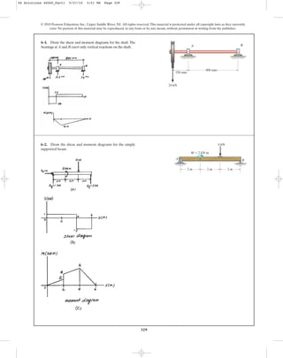
  • 1. 329 6–1. Draw the shear and moment diagrams for the shaft.The bearings at A and B exert only vertical reactions on the shaft. © 2010 Pearson Education, Inc., Upper Saddle River, NJ. All rights reserved.This material is protected under all copyright laws as they currently exist. No portion of this material may be reproduced, in any form or by any means, without permission in writing from the publisher. A B 250 mm 800 mm 24 kN 6–2. Draw the shear and moment diagrams for the simply supported beam. A B M ϭ 2 kNиm 4 kN 2 m 2 m 2 m 06 Solutions 46060_Part1 5/27/10 3:51 PM Page 329
  • 2. 330 © 2010 Pearson Education, Inc., Upper Saddle River, NJ. All rights reserved.This material is protected under all copyright laws as they currently exist. No portion of this material may be reproduced, in any form or by any means, without permission in writing from the publisher. a ©Fx = 0; Ax - 3 5 (4000) = 0; Ax = 2400 lb;+ + c©Fy = 0; -Ay + 4 5 (4000) - 1200 = 0; Ay = 2000 lb FA = 4000 lb+ ©MA = 0; 4 5 FA(3) - 1200(8) = 0; 6–3. The engine crane is used to support the engine, which has a weight of 1200 lb.Draw the shear and moment diagrams of the boom ABC when it is in the horizontal position shown. 5 ft3 ft CB 4 ft A The free-body diagram of the beam’s right segment sectioned through an arbitrary point shown in Fig.a will be used to write the shear and moment equations of the beam. *6–4. Draw the shear and moment diagrams for the canti- lever beam. 2 kN/m 6 kNиm 2 m A ‚ (1) a ‚(2)+©M = 0; -M - 2(2 - x)c 1 2 (2 - x)d - 6 = 0 M = {-x2 + 4x - 10}kN # m + c©Fy = 0; V - 2(2 - x) = 0 V = {4 - 2x} kN The shear and moment diagrams shown in Figs. b and c are plotted using Eqs. (1) and (2), respectively.The value of the shear and moment at is evaluated using Eqs. (1) and (2). MΗx= 0 = C -0 + 4(0) - 10D = -10kN # m VΗx = 0 = 4 - 2(0) = 4 kN x = 0 06 Solutions 46060_Part1 5/27/10 3:51 PM Page 330
  • 3. 331 © 2010 Pearson Education, Inc., Upper Saddle River, NJ. All rights reserved.This material is protected under all copyright laws as they currently exist. No portion of this material may be reproduced, in any form or by any means, without permission in writing from the publisher. 6–5. Draw the shear and moment diagrams for the beam. 2 m 3 m 10 kN 8 kN 15 kNиm 6–6. Draw the shear and moment diagrams for the overhang beam. A B C 4 m 2 m 8 kN/m 6–7. Draw the shear and moment diagrams for the compound beam which is pin connected at B. 4 ft 6 kip 8 kip A C B 6 ft 4 ft 4 ft 06 Solutions 46060_Part1 5/27/10 3:51 PM Page 331
  • 4. 332 The free-body diagram of the beam’s left segment sectioned through an arbitrary point shown in Fig. b will be used to write the shear and moment equations. The intensity of the triangular distributed load at the point of sectioning is Referring to Fig. b, w = 150a x 12 b = 12.5x *6–8. Draw the shear and moment diagrams for the simply supported beam. © 2010 Pearson Education, Inc., Upper Saddle River, NJ. All rights reserved.This material is protected under all copyright laws as they currently exist. No portion of this material may be reproduced, in any form or by any means, without permission in writing from the publisher. A B 150 lb/ft 12 ft 300 lbиft ‚ (1) a ‚(2)+©M = 0; M + 1 2 (12.5x)(x)a x 3 b - 275x = 0 M = {275x - 2.083x3 }lb # ft + c ©Fy = 0; 275 - 1 2 (12.5x)(x) - V = 0 V = {275 - 6.25x2 }lb The shear and moment diagrams shown in Figs. c and d are plotted using Eqs. (1) and (2), respectively. The location where the shear is equal to zero can be obtained by setting in Eq. (1). The value of the moment at is evaluated using Eq. (2). MΗx= 6.633 ft = 275(6.633) - 2.083(6.633)3 = 1216 lb # ft x = 6.633 ft (V = 0) 0 = 275 - 6.25x2 x = 6.633 ft V = 0 06 Solutions 46060_Part1 5/27/10 3:51 PM Page 332
  • 5. 333 6–9. Draw the shear and moment diagrams for the beam. Hint: The 20-kip load must be replaced by equivalent loadings at point C on the axis of the beam. © 2010 Pearson Education, Inc., Upper Saddle River, NJ. All rights reserved.This material is protected under all copyright laws as they currently exist. No portion of this material may be reproduced, in any form or by any means, without permission in writing from the publisher. B 4 ft A 4 ft 4 ft 15 kip 20 kip C 1 ft Equations of Equilibrium: Referring to the free-body diagram of the frame shown in Fig. a, a Shear and Moment Diagram: The couple moment acting on B due to ND is . The loading acting on member ABC is shown in Fig. b and the shear and moment diagrams are shown in Figs. c and d. MB = 300(1.5) = 450 lb # ft ND = 300 lb +©MA = 0; ND(1.5) - 150(3) = 0 Ay = 150 lb + c©Fy = 0; Ay - 150 = 0 6–10. Members ABC and BD of the counter chair are rigidly connected at B and the smooth collar at D is allowed to move freely along the vertical slot. Draw the shear and moment diagrams for member ABC. A D B C P ϭ 150 lb 1.5 ft1.5 ft 1.5 ft 06 Solutions 46060_Part1 5/27/10 3:51 PM Page 333
  • 6. Support Reactions: a Shear and Moment Diagram: ©Fx = 0; -Cx + 4 5 (2000) = 0 Cx = 1600 lb:+ + c©Fy = 0; -800 + 3 5 (2000) - Cy = 0 Cy = 400 lb FDE = 2000 lb +©MC = 0; 800(10) - 3 5 FDE(4) - 4 5 FDE(2) = 0 6–11. The overhanging beam has been fabricated with a projected arm BD on it. Draw the shear and moment diagrams for the beam ABC if it supports a load of 800 lb. Hint: The loading in the supporting strut DE must be replaced by equivalent loads at point B on the axis of the beam. 334 © 2010 Pearson Education, Inc., Upper Saddle River, NJ. All rights reserved.This material is protected under all copyright laws as they currently exist. No portion of this material may be reproduced, in any form or by any means, without permission in writing from the publisher. 800 lb D B A E C 6 ft 4 ft 5 ft 2 ft *6–12. A reinforced concrete pier is used to support the stringers for a bridge deck. Draw the shear and moment diagrams for the pier when it is subjected to the stringer loads shown. Assume the columns at A and B exert only vertical reactions on the pier. 1 m 1 m 1 m 1 m1.5 m 60 kN 60 kN35 kN 35 kN 35 kN 1.5 m A B 06 Solutions 46060_Part1 5/27/10 3:51 PM Page 334
  • 7. 335 © 2010 Pearson Education, Inc., Upper Saddle River, NJ. All rights reserved.This material is protected under all copyright laws as they currently exist. No portion of this material may be reproduced, in any form or by any means, without permission in writing from the publisher. Support Reactions: From the FBD of segment BD a From the FBD of segment AB a + c©Fy = 0; P - P = 0 (equilibrium is statisfied!) +©MA = 0; P(2a) - P(a) - MA = 0 MA = Pa ©Fx = 0; Bx = 0:+ + c©Fy = 0; Cy - P - P = 0 Cy = 2P +©MC = 0; By (a) - P(a) = 0 By = P 6–13. Draw the shear and moment diagrams for the compound beam.It is supported by a smooth plate at A which slides within the groove and so it cannot support a vertical force,although it can support a moment and axial load. a A B a a a P P C D 10 in. 4 in. 50 in. A B C D 120Њ 6–14. The industrial robot is held in the stationary position shown.Draw the shear and moment diagrams of the arm ABC if it is pin connected at A and connected to a hydraulic cylinder (two-force member) BD. Assume the arm and grip have a uniform weight of 1.5 lb͞in. and support the load of 40 lb at C. 06 Solutions 46060_Part1 5/27/10 3:51 PM Page 335
  • 8. 336 © 2010 Pearson Education, Inc., Upper Saddle River, NJ. All rights reserved.This material is protected under all copyright laws as they currently exist. No portion of this material may be reproduced, in any form or by any means, without permission in writing from the publisher. For ‚ Ans. a ‚ Ans. For Ans. a ‚ Ans. For ‚ Ans. a Ans.M = (500x - 3000) lb ft +©MNA = 0; -M - 500(5.5 - x) - 250 = 0 + c©Fy = 0; V - 500 = 0 V = 500 lb 5 ft 6 x … 6 ft M = {-580x + 2400} lb ft +©MNA = 0; M + 800(x - 3) - 220x = 0 V = -580 lb + c©Fy = 0; 220 - 800 - V = 0 3 ft 6 x 6 5 ft M = (220x) lb ft +©MNA = 0. M - 220x = 0 + c©Fy = 0. 220 - V = 0 V = 220 lb 0 6 x 6 3 ft *6–16. Draw the shear and moment diagrams for the shaft and determine the shear and moment throughout the shaft as a function of x. The bearings at A and B exert only vertical reactions on the shaft. x BA 800 lb 500 lb 3 ft 2 ft 0.5 ft 0.5 ft 06 Solutions 46060_Part1 5/27/10 3:51 PM Page 336
  • 9. 337 © 2010 Pearson Education, Inc., Upper Saddle River, NJ. All rights reserved.This material is protected under all copyright laws as they currently exist. No portion of this material may be reproduced, in any form or by any means, without permission in writing from the publisher. (1) a (2)+©M = 0; M + 1 2 (33.33x)(x)a x 3 b + 300x = 0 M = {-300x - 5.556x3 } lb # ft + c©Fy = 0; -300 - 1 2 (33.33x)(x) - V = 0 V = {-300 - 16.67x2 } lb •6–17. Draw the shear and moment diagrams for the cantilevered beam. 300 lb 200 lb/ft A 6 ft The free-body diagram of the beam’s left segment sectioned through an arbitrary point shown in Fig. b will be used to write the shear and moment equations. The intensity of the triangular distributed load at the point of sectioning is Referring to Fig. b, w = 200a x 6 b = 33.33x The shear and moment diagrams shown in Figs. c and d are plotted using Eqs. (1) and (2), respectively. 06 Solutions 46060_Part1 5/27/10 3:51 PM Page 337
  • 10. 338 © 2010 Pearson Education, Inc., Upper Saddle River, NJ. All rights reserved.This material is protected under all copyright laws as they currently exist. No portion of this material may be reproduced, in any form or by any means, without permission in writing from the publisher. Support Reactions: As shown on FBD. Shear and Moment Function: For : Ans. a Ans. For : Ans. a Ans.M = {8.00x - 120} kip # ft +©MNA = 0; -M - 8(10 - x) - 40 = 0 + c©Fy = 0; V - 8 = 0 V = 8.00 kip 6 ft 6 x … 10 ft M = {-x2 + 30.0x - 216} kip # ft +©MNA = 0; M + 216 + 2xa x 2 b - 30.0x = 0 V = {30.0 - 2x} kip + c©Fy = 0; 30.0 - 2x - V = 0 0 … x 6 6 ft 6–18. Draw the shear and moment diagrams for the beam, and determine the shear and moment throughout the beam as functions of x. 6 ft 4 ft 2 kip/ft 8 kip x 10 kip 40 kipиft A 30 kipиft B 5 ft 5 ft 2 kip/ft 5 ft 6–19. Draw the shear and moment diagrams for the beam. 06 Solutions 46060_Part1 5/27/10 3:51 PM Page 338
  • 11. 339 © 2010 Pearson Education, Inc., Upper Saddle River, NJ. All rights reserved.This material is protected under all copyright laws as they currently exist. No portion of this material may be reproduced, in any form or by any means, without permission in writing from the publisher. Since the area under the curved shear diagram can not be computed directly, the value of the moment at will be computed using the method of sections. By referring to the free-body diagram shown in Fig. b, a Ans.+©M = 0; MΗx= 3 m + 1 2 (10)(3)(1) - 20(3) = 0 MΗx= 3m = 45 kN # m x = 3 m *6–20. Draw the shear and moment diagrams for the simply supported beam. 10 kN 10 kN/m 3 m A B 3 m 06 Solutions 46060_Part1 5/27/10 3:51 PM Page 339
  • 12. •6–21. The beam is subjected to the uniform distributed load shown. Draw the shear and moment diagrams for the beam. 340 © 2010 Pearson Education, Inc., Upper Saddle River, NJ. All rights reserved.This material is protected under all copyright laws as they currently exist. No portion of this material may be reproduced, in any form or by any means, without permission in writing from the publisher. BA C 2 m 1.5 m 1 m 2 kN/m Equations of Equilibrium: Referring to the free-body diagram of the beam shown in Fig. a, a Shear and Moment Diagram: The vertical component of FBC is .The shear and moment diagrams are shown in Figs. c and d.= 4.5 kN AFBCBy = 7.5a 3 5 b Ay = 1.5 kN + c©Fy = 0; Ay + 7.5a 3 5 b - 2(3) = 0 FBC = 7.5 kN +©MA = 0; FBCa 3 5 b(2) - 2(3)(1.5) = 0 06 Solutions 46060_Part1 5/27/10 3:51 PM Page 340
  • 13. 341 © 2010 Pearson Education, Inc., Upper Saddle River, NJ. All rights reserved.This material is protected under all copyright laws as they currently exist. No portion of this material may be reproduced, in any form or by any means, without permission in writing from the publisher. (1) a (2) Region , Fig. c (3) a (4)+©M = 0; -M - 4(6 - x)c 1 2 (6 - x)d = 0 M = {-2(6 - x)2 }kN # m + c©Fy = 0; V - 4(6 - x) = 0 V = {24 - 4x} kN 3 m 6 x … 6 m +©M = 0; M + 1 2 a 4 3 xb(x)a x 3 b + 4x = 0 M = e - 2 9 x3 - 4xf kN # m + c©Fy = 0; -4 - 1 2 a 4 3 xb(x) - V = 0 V = e - 2 3 x2 - 4f kN 6–22. Draw the shear and moment diagrams for the overhang beam. 4 kN/m 3 m 3 m A B Since the loading is discontinuous at support B,the shear and moment equations must be written for regions and of the beam.The free-body diagram of the beam’s segment sectioned through an arbitrary point within these two regions is shown in Figs. b and c. Region , Fig. b0 … x 6 3 m 3 m 6 x … 6 m0 … x 6 3 m The shear diagram shown in Fig. d is plotted using Eqs. (1) and (3). The value of shear just to the left and just to the right of the support is evaluated using Eqs. (1) and (3), respectively. The moment diagram shown in Fig. e is plotted using Eqs. (2) and (4). The value of the moment at support B is evaluated using either Eq. (2) or Eq. (4). or MΗx= 3 m = -2(6 - 3)2 = -18 kN # m MΗx=3 m = - 2 9 (33 ) - 4(3) = -18 kN # m VΗx=3 m+ = 24 - 4(3) = 12 kN VΗx= 3 m- = - 2 3 (32 ) - 4 = -10 kN 06 Solutions 46060_Part1 5/27/10 3:51 PM Page 341
  • 14. 6–23. Draw the shear and moment diagrams for the beam. It is supported by a smooth plate at A which slides within the groove and so it cannot support a vertical force, although it can support a moment and axial load. 342 © 2010 Pearson Education, Inc., Upper Saddle River, NJ. All rights reserved.This material is protected under all copyright laws as they currently exist. No portion of this material may be reproduced, in any form or by any means, without permission in writing from the publisher. L A B w a Substitute ; To get absolute minimum moment, ‚ Ans.a = L 22 L - L2 2a = L - a w 2 (L - L2 2a )2 = w 2 (L - a)2 Mmax (+) = Mmax (-) Mmax (-) = w(L - a)2 2 ©M = 0; Mmax (-) - w(L - a) (L - a) 2 = 0 = w 2 aL - L2 2a b 2 Mmax (+) = awL - wL2 2a b aL - L2 2a b - w 2 aL - L2 2a b 2 x = L - L2 2a +©M = 0; Mmax (+) + wxa x 2 b - awL - wL2 2a bx = 0 x = L - L2 2a + c©Fy = 0; wL - wL2 2a - wx = 0 *6–24. Determine the placement distance a of the roller support so that the largest absolute value of the moment is a minimum. Draw the shear and moment diagrams for this condition. a w L A B 06 Solutions 46060_Part1 5/27/10 3:51 PM Page 342
  • 15. 343 © 2010 Pearson Education, Inc., Upper Saddle River, NJ. All rights reserved.This material is protected under all copyright laws as they currently exist. No portion of this material may be reproduced, in any form or by any means, without permission in writing from the publisher. Support Reactions: As shown on FBD. Shear and Moment Function: a Shear and Moment Diagram: +©MNA = 0; M + mx - mL = 0 M = m(L - x) + c©Fy = 0; V = 0 6–25. The beam is subjected to the uniformly distributed moment m ( ). Draw the shear and moment diagrams for the beam. moment>length L A m a Substitute , M = 0.0345 w0L2 x = 0.7071L +©MNA = 0; M + 1 2 a w0x L b(x)a x 3 b - w0L 4 ax - L 3 b = 0 x = 0.7071 L + c©Fy = 0; w0L 4 - 1 2 a w0x L b(x) = 0 6–27. Draw the shear and moment diagrams for the beam. B w0 A 2L 3 L 3 06 Solutions 46060_Part1 5/27/10 3:51 PM Page 343
  • 16. Support Reactions: As shown on FBD. Shear and Moment Diagram: Shear and moment at can be determined using the method of sections. a M = 5w0 L2 54 +©MNA = 0; M + w0 L 6 a L 9 b - w0 L 3 a L 3 b = 0 + c©Fy = 0; w0 L 3 - w0 L 6 - V = 0 V = w0 L 6 x = L>3 344 © 2010 Pearson Education, Inc., Upper Saddle River, NJ. All rights reserved.This material is protected under all copyright laws as they currently exist. No portion of this material may be reproduced, in any form or by any means, without permission in writing from the publisher. *6–28. Draw the shear and moment diagrams for the beam. – 3 L – 3 L – 3 L w0 A B 06 Solutions 46060_Part1 5/27/10 3:51 PM Page 344
  • 17. 345 © 2010 Pearson Education, Inc., Upper Saddle River, NJ. All rights reserved.This material is protected under all copyright laws as they currently exist. No portion of this material may be reproduced, in any form or by any means, without permission in writing from the publisher. From FBD(a) a From FBD(b) a M = 25.31 kN # m +©MNA = 0; M + 11.25(1.5) - 9.375(4.5) = 0 M = 25.67 kN # m +©MNA = 0; M + (0.5556)A4.1082 B a 4.108 3 b - 9.375(4.108) = 0 + c©Fy = 0; 9.375 - 0.5556x2 = 0 x = 4.108 m •6–29. Draw the shear and moment diagrams for the beam. B A 4.5 m 4.5 m 5 kN/m5 kN/m 06 Solutions 46060_Part1 5/27/10 3:51 PM Page 345
  • 18. 346 © 2010 Pearson Education, Inc., Upper Saddle River, NJ. All rights reserved.This material is protected under all copyright laws as they currently exist. No portion of this material may be reproduced, in any form or by any means, without permission in writing from the publisher. Support Reactions: From the FBD of segment AB a From the FBD of segment BC a Shear and Moment Diagram: The maximum positive moment occurs when . a Mmax = 346.4 lb # ft +©MNA = 0; 150(3.464) - 12.5A3.4642 B a 3.464 3 b - Mmax = 0 + c©Fy = 0; 150.0 - 12.5x2 = 0 x = 3.464 ft V = 0 ©Fx = 0; Cx = 0:+ + c©Fy = 0; Cy - 150.0 - 225 = 0 Cy = 375.0 lb MC = 675.0 lb # ft +©MC = 0; 225(1) + 150.0(3) - MC = 0 ©Fx = 0; Bx = 0:+ + c©Fy = 0; By - 450 + 300.0 = 0 By = 150.0 lb +©MB = 0; 450(4) - Ay (6) = 0 Ay = 300.0 lb 6–30. Draw the shear and moment diagrams for the compound beam. BA 6 ft 150 lb/ft 150 lb/ft 3 ft C 06 Solutions 46060_Part1 5/27/10 3:51 PM Page 346
  • 19. 347 © 2010 Pearson Education, Inc., Upper Saddle River, NJ. All rights reserved.This material is protected under all copyright laws as they currently exist. No portion of this material may be reproduced, in any form or by any means, without permission in writing from the publisher. Support Reactions: As shown on FBD. Shear and Moment Functions: For Ans. a Ans. For Ans. a Ans.M = - w0 3L (L - x)3 +©MNA = 0; -M - 1 2 c 2w0 L (L - x)d(L - x)a L - x 3 b = 0 V = w0 L (L - x)2 + c©Fy = 0; V - 1 2 c 2w0 L (L - x)d(L - x) = 0 L>2 6 x … L M = w0 24 A -12x2 + 18Lx - 7L2 ) +©MNA = 0; 7w0 L2 24 - 3w0 L 4 x + w0 xa x 2 b + M = 0 V = w0 4 (3L - 4x) + c©Fy = 0; 3w0 L 4 -w0x - V = 0 0 … x 6 L>2 6–31. Draw the shear and moment diagrams for the beam and determine the shear and moment in the beam as functions of x. x BA w0 L – 2 L – 2 06 Solutions 46060_Part1 5/27/10 3:51 PM Page 347
  • 20. 348 Ans.w0 = 1.2 kN>m + c©Fy = 0; 2(w0)(20)a 1 2 b - 60(0.4) = 0 *6–32. The smooth pin is supported by two leaves A and B and subjected to a compressive load of 0.4 kN͞m caused by bar C. Determine the intensity of the distributed load w0 of the leaves on the pin and draw the shear and moment diagram for the pin. © 2010 Pearson Education, Inc., Upper Saddle River, NJ. All rights reserved.This material is protected under all copyright laws as they currently exist. No portion of this material may be reproduced, in any form or by any means, without permission in writing from the publisher. 20 mm 0.4 kN/m w0 20 mm 60 mm w0 A B C Ski: Ans. Segment: a+©M = 0; M - 30(0.5) = 0; M = 15.0 lb # ft + c©Fy = 0; 30 - V = 0; V = 30.0 lb w = 40.0 lb>ft + c©Fy = 0; 1 2 w(1.5) + 3w + 1 2 w(1.5) - 180 = 0 •6–33. The ski supports the 180-lb weight of the man. If the snow loading on its bottom surface is trapezoidal as shown, determine the intensity w, and then draw the shear and moment diagrams for the ski. 180 lb w w 1.5 ft 3 ft 1.5 ft 3 ft 06 Solutions 46060_Part1 5/27/10 3:51 PM Page 348
  • 21. 349 © 2010 Pearson Education, Inc., Upper Saddle River, NJ. All rights reserved.This material is protected under all copyright laws as they currently exist. No portion of this material may be reproduced, in any form or by any means, without permission in writing from the publisher. 6–34. Draw the shear and moment diagrams for the compound beam. 3 m 3 m 1.5 m 1.5 m 5 kN 3 kN/m A B C D 6–35. Draw the shear and moment diagrams for the beam and determine the shear and moment as functions of x. 3 m 3 m x A B 200 N/m 400 N/m Support Reactions: As shown on FBD. Shear and Moment Functions: For : Ans. a Ans. For : Ans. Set , a Ans. Substitute , M = 691 N # mx = 3.87 m M = e - 100 9 x3 + 500x - 600 f N # m + 200(x - 3)a x - 3 2 b - 200x = 0 +©MNA = 0; M + 1 2 c 200 3 (x - 3)d(x - 3)a x - 3 3 b x = 3.873 mV = 0 V = e - 100 3 x2 + 500 f N + c©Fy = 0; 200 - 200(x - 3) - 1 2 c 200 3 (x - 3)d(x - 3) - V = 0 3 m 6 x … 6 m M = (200 x) N # m +©MNA = 0; M - 200 x = 0 + c©Fy = 0; 200 - V = 0 V = 200 N 0 … x 6 3 m 06 Solutions 46060_Part1 5/27/10 3:51 PM Page 349
  • 22. 350 *6–36. Draw the shear and moment diagrams for the overhang beam. © 2010 Pearson Education, Inc., Upper Saddle River, NJ. All rights reserved.This material is protected under all copyright laws as they currently exist. No portion of this material may be reproduced, in any form or by any means, without permission in writing from the publisher. A B M ϭ 10 kNиm 2 m 2 m 2 m 6 kN 18 kN 6–37. Draw the shear and moment diagrams for the beam. B 4.5 m 4.5 m 50 kN/m A 50 kN/m A 06 Solutions 46060_Part1 5/27/10 3:51 PM Page 350
  • 23. 351 © 2010 Pearson Education, Inc., Upper Saddle River, NJ. All rights reserved.This material is protected under all copyright laws as they currently exist. No portion of this material may be reproduced, in any form or by any means, without permission in writing from the publisher. 6–38. The dead-weight loading along the centerline of the airplane wing is shown. If the wing is fixed to the fuselage at A, determine the reactions at A, and then draw the shear and moment diagram for the wing. Support Reactions: Ans. a Ans. Ans. Shear and Moment Diagram: ©Fx = 0; Ax = 0:+ MA = 18.583 kip # ft = 18.6 kip # ft + 1.25(2.5) + 0.375(1.667) + MA = 0 +©MA = 0; 1.00(7.667) + 3(5) - 15(3) Ay = 9.375 kip + c©Fy = 0; -1.00 - 3 + 15 - 1.25 - 0.375 - Ay = 0 3 ft 400 lb/ft 250 lb/ft 3000 lb 15 000 lb 2 ft8 ft A 6–39. The compound beam consists of two segments that are pinned together at B. Draw the shear and moment diagrams if it supports the distributed loading shown. 2/3 L A C B 1/3 L w a M = 0.0190 wL2 +©M = 0; M + 1 2 w L (0.385L)2 a 1 3 b(0.385L) - 2wL 27 (0.385L) = 0 x = A 4 27 L = 0.385 L + c©Fy = 0; 2wL 27 - 1 2 w L x2 = 0 06 Solutions 46060_Part1 5/27/10 3:51 PM Page 351
  • 24. 352 © 2010 Pearson Education, Inc., Upper Saddle River, NJ. All rights reserved.This material is protected under all copyright laws as they currently exist. No portion of this material may be reproduced, in any form or by any means, without permission in writing from the publisher. A B 2 m 0.8 kN/m 1 m 2 m 1 m 2 m 1 m1 m C D E F 3 kN 3 kN A B 2 m 2 m 10 kN 10 kN 15 kNиm 2 m *6–40. Draw the shear and moment diagrams for the simply supported beam. 6–41. Draw the shear and moment diagrams for the compound beam. The three segments are connected by pins at B and E. 06 Solutions 46060_Part1 5/27/10 3:51 PM Page 352
  • 25. 353 © 2010 Pearson Education, Inc., Upper Saddle River, NJ. All rights reserved.This material is protected under all copyright laws as they currently exist. No portion of this material may be reproduced, in any form or by any means, without permission in writing from the publisher. Support Reactions: From the FBD of segment AB a From the FBD of segment BD a From the FBD of segment AB Shear and Moment Diagram: ©Fx = 0; Ax = 0:+ ©Fx = 0; Bx = 0:+ Cy = 20.0 kN + c©Fy = 0; Cy - 5.00 - 5.00 - 10.0 = 0 Dy = 5.00 kN +©MC = 0; 5.00(1) + 10.0(0) - Dy (1) = 0 + c©Fy = 0; Ay - 10.0 + 5.00 = 0 Ay = 5.00 kN +©MA = 0; By (2) - 10.0(1) = 0 By = 5.00 kN 6–42. Draw the shear and moment diagrams for the compound beam. BA C D 2 m 1 m 1 m 5 kN/m A C 3 ft 8 ft 3 kip/ft 5 ft B 8 kip6–43. Draw the shear and moment diagrams for the beam. The two segments are joined together at B. 06 Solutions 46060_Part1 5/27/10 3:51 PM Page 353
  • 26. 354 *6–44. Draw the shear and moment diagrams for the beam. © 2010 Pearson Education, Inc., Upper Saddle River, NJ. All rights reserved.This material is protected under all copyright laws as they currently exist. No portion of this material may be reproduced, in any form or by any means, without permission in writing from the publisher. •6–45. Draw the shear and moment diagrams for the beam. a Substitute M = 0.0394 w0L2 x = 0.630L M = w0Lx 12 - w0x4 12L2 +©M = 0; w0L 12 (x) - w0x3 3L2 a 1 4 xb - M = 0 x = a 1 4 b 1>3 L = 0.630 L + c©Fy = 0; w0L 12 - w0x3 3L2 = 0 3L 4 w0 L2 L L 0 x3 dx w0 L 3 =x = LA xdA LA dA = FR = LA dA = L L 0 wdx = w0 L2 L L 0 x2 dx = w0L 3 L A B x w w0 w ϭ w0 L2 x2 x = 1 8 1 8 0 x3 dx 21.33 = 6.0 ft FR = 1 8 L 8 0 x 2 dx = 21.33 kip 8 ft A B x w w ϭ x2 8 kip/ft 1 8 06 Solutions 46060_Part1 5/27/10 3:51 PM Page 354
  • 27. 355 © 2010 Pearson Education, Inc., Upper Saddle River, NJ. All rights reserved.This material is protected under all copyright laws as they currently exist. No portion of this material may be reproduced, in any form or by any means, without permission in writing from the publisher. 6–46. Draw the shear and moment diagrams for the beam. FR = LA dA = w0 L L 0 sina p L xbdx = 2w0 L p w0 w ϭ w0 sin x BA w x L – 2 p – L L – 2 The moment of inertia of the cross-section about z and y axes are For the bending about z axis, . Ans. For the bending about y axis, . Ans. The bending stress distribution for bending about z and y axes are shown in Fig. a and b respectively. smax = Mc Iy = 90(103 ) (0.1) 0.1 (10-3 ) = 90 (106 )Pa = 90 MPa C = 0.1 m smax = Mc Iz = 90(103 ) (0.075) 56.25 (10-6 ) = 120(106 )Pa = 120 MPa c = 0.075 m Iy = 1 12 (0.15)(0.23 ) = 0.1(10-3 ) m4 Iz = 1 12 (0.2)(0.153 ) = 56.25(10-6 ) m4 6–47. A member having the dimensions shown is used to resist an internal bending moment of Determine the maximum stress in the member if the moment is applied (a) about the z axis (as shown) (b) about the y axis. Sketch the stress distribution for each case. M = 90 kN # m. 200 mm 150 mm z y x M 06 Solutions 46060_Part1 5/27/10 3:51 PM Page 355
  • 28. 356 Section Properties: Maximum Bending Stress: Applying the flexure formula Ans.M = 129.2 kip # in = 10.8 kip # ft 10 = M (10.5 - 3.4) 91.73 smax = Mc I = 91.73 in4 + 1 12 (0.5)A103 B + 0.5(10)(5.5 - 3.40)2 + 2c 1 12 (0.5)(33 ) + 0.5(3)(3.40 - 2)2 d INA = 1 12 (4)A0.53 B + 4(0.5)(3.40 - 0.25)2 = 0.25(4)(0.5) + 2[2(3)(0.5)] + 5.5(10)(0.5) 4(0.5) + 2[(3)(0.5)] + 10(0.5) = 3.40 in. y = © y A ©A *6–48. Determine the moment M that will produce a maximum stress of 10 ksi on the cross section. © 2010 Pearson Education, Inc., Upper Saddle River, NJ. All rights reserved.This material is protected under all copyright laws as they currently exist. No portion of this material may be reproduced, in any form or by any means, without permission in writing from the publisher. 3 in. D A B 0.5 in. M 0.5 in. 3 in. C 10 in. 0.5 in.0.5 in. 06 Solutions 46060_Part1 5/27/10 3:51 PM Page 356
  • 29. 357 Section Properties: Maximum Bending Stress: Applying the flexure formula Ans. Ans.(sc)max = 4(103 )(12)(3.40) 91.73 = 1779.07 psi = 1.78 ksi (st)max = 4(103 )(12)(10.5 - 3.40) 91.73 = 3715.12 psi = 3.72 ksi smax = Mc I = 91.73 in4 + 1 12 (0.5)A103 B + 0.5(10)(5.5 - 3.40)2 + 2c 1 12 (0.5)(33 ) + 0.5(3)(3.40 - 2)2 d INA = 1 12 (4)A0.53 B + 4(0.5)(3.40 - 0.25)2 = 0.25(4)(0.5) + 2[2(3)(0.5)] + 5.5(10)(0.5) 4(0.5) + 2[(3)(0.5)] + 10(0.5) = 3.40 in. y = © y A ©A •6–49. Determine the maximum tensile and compressive bending stress in the beam if it is subjected to a moment of M = 4 kip # ft. © 2010 Pearson Education, Inc., Upper Saddle River, NJ. All rights reserved.This material is protected under all copyright laws as they currently exist. No portion of this material may be reproduced, in any form or by any means, without permission in writing from the publisher. 3 in. D A B 0.5 in. M 0.5 in. 3 in. C 10 in. 0.5 in.0.5 in. 06 Solutions 46060_Part1 5/27/10 3:51 PM Page 357
  • 30. 358 Ans. Ans.sB = 30(13.24 - 10)(10-3 ) 0.095883(10-6 ) = 1.01 MPa sA = 30(35 - 13.24)(10-3 ) 0.095883(10-6 ) = 6.81 MPa = 0.095883(10-6 ) m4 + 2c 1 12 (5)(203 ) + 5(20)(20 - 13.24)2 d + 2c 1 12 (12)(53 ) + 12(5)(32.5 - 13.24)2 d + c 1 12 (34)(53 ) + 34(5)(13.24 - 7.5)2 d I = c 1 12 (50)(53 ) + 50(5)(13.24 - 2.5)2 d = 13.24 mm y = 2.5(50)(5) + 7.5(34)(5) + 2[20(5)(20)] + 2[(32.5)(12)(5)] 50(5) + 34(5) + 2[5(20)] + 2[(12)(5)] Ans. Ans.M = 771 N # m s = Mc I ; 175(106 ) = M(35 - 13.24)(10-3 ) 0.095883(10-6 ) = 0.095883(10-6 ) m4 + 2c 1 12 (5)(203 ) + 5(20)(20 - 13.24)2 d + 2c 1 12 (12)(53 ) + 12(5)(32.5 - 13.24)2 d I = c 1 12 (50)(53 ) + 50(5)(13.24 - 2.5)2 d + c 1 12 (34)(53 ) + 34(5)(13.24 - 7.5)2 d y = ©y2 A ©A = 2.5(50)(5) + 7.5(34)(5) + 2[20(5)(20)] + 2[(32.5)(12)(5)] 50(5) + 34(5) + 2[5(20)] + 2[(12)(5)] = 13.24 mm sC = 30(13.24)(10-3 ) 0.095883(10-6 ) = 4.14 MPa 6–50. The channel strut is used as a guide rail for a trolley. If the maximum moment in the strut is determine the bending stress at points A, B, and C. M = 30 N # m, 6–51. The channel strut is used as a guide rail for a trolley. If the allowable bending stress for the material is determine the maximum bending moment the strut will resist. sallow = 175 MPa, © 2010 Pearson Education, Inc., Upper Saddle River, NJ. All rights reserved.This material is protected under all copyright laws as they currently exist. No portion of this material may be reproduced, in any form or by any means, without permission in writing from the publisher. 50 mm 30 mm A B C 5 mm 5 mm 5 mm 5 mm 5 mm 7 mm 7 mm10 mm 50 mm 30 mm A B C 5 mm 5 mm 5 mm 5 mm 5 mm 7 mm 7 mm10 mm 06 Solutions 46060_Part1 5/27/10 3:51 PM Page 358
  • 31. 359 © 2010 Pearson Education, Inc., Upper Saddle River, NJ. All rights reserved.This material is protected under all copyright laws as they currently exist. No portion of this material may be reproduced, in any form or by any means, without permission in writing from the publisher. Section Property: Bending Stress: Applying the flexure formula Resultant Force and Moment: For board A or B Ans.sca M¿ M b = 0.8457(100%) = 84.6 % M¿ = F(0.17619) = 4.80M(0.17619) = 0.8457 M = 4.800 M F = 822.857M(0.025)(0.2) + 1 2 (1097.143M - 822.857M)(0.025)(0.2) sD = M(0.075) 91.14583(10-6 ) = 822.857 M sE = M(0.1) 91.14583(10-6 ) = 1097.143 M s = My I I = 1 12 (0.2)A0.23 B - 1 12 (0.15)A0.153 B = 91.14583A10-6 B m4 *6–52. The beam is subjected to a moment M. Determine the percentage of this moment that is resisted by the stresses acting on both the top and bottom boards, A and B, of the beam. 150 mm 25 mm 25 mm 150 mm M 25 mm 25 mm B A D Section Property: Bending Stress: Applying the flexure formula Ans. Ans.smax = Mc I = 36458(0.1) 91.14583(10-6 ) = 40.0 MPa M = 36458 N # m = 36.5 kN # m 30A106 B = M(0.075) 91.14583(10-6 ) s = My I I = 1 12 (0.2)A0.23 B - 1 12 (0.15)A0.153 B = 91.14583A10-6 B m4 •6–53. Determine the moment M that should be applied to the beam in order to create a compressive stress at point D of Also sketch the stress distribution acting over the cross section and compute the maximum stress developed in the beam. sD = 30 MPa. 150 mm 25 mm 25 mm 150 mm M 25 mm 25 mm B A D 06 Solutions 46060_Part1 5/27/10 3:51 PM Page 359
  • 32. 360 Ans. sC = My I = 600 (0.05625) 34.53125 (10-6 ) = 0.977 MPa = 2.06 MPa = 600 (0.175 - 0.05625) 34.53125 (10-6 ) smax = sB = Mc I = 34.53125 (10-6 ) m4 + 2 a 1 12 b(0.02)(0.153 ) + 2(0.15)(0.02)(0.043752 ) I = 1 12 (0.24)(0.0253 ) + (0.24)(0.025)(0.043752 ) y = (0.0125)(0.24)(0.025) + 2 (0.1)(0.15)(0.2) 0.24 (0.025) + 2 (0.15)(0.02) = 0.05625 m Ans.F = 1 2 (0.025)(0.9774 + 0.5430)(106 )(0.240) = 4.56 kN sb = My I = 600(0.05625 - 0.025) 34.53125(10-6 ) = 0.5430 MPa s1 = My I = 600(0.05625) 34.53125(10-6 ) = 0.9774 MPa = 34.53125 (10-6 ) m4 + 2 a 1 12 b(0.02)(0.153 ) + 2(0.15)(0.02)(0.043752 ) I = 1 12 (0.24)(0.0253 ) + (0.24)(0.025)(0.043752 ) y = (0.0125)(0.24)(0.025) + 2 (0.15)(0.1)(0.02) 0.24 (0.025) + 2 (0.15)(0.02) = 0.05625 m 6–54. The beam is made from three boards nailed together as shown. If the moment acting on the cross section is determine the maximum bending stress in the beam. Sketch a three-dimensional view of the stress distribution acting over the cross section. M = 600 N # m, 6–55. The beam is made from three boards nailed together as shown. If the moment acting on the cross section is determine the resultant force the bending stress produces on the top board. M = 600 N # m, © 2010 Pearson Education, Inc., Upper Saddle River, NJ. All rights reserved.This material is protected under all copyright laws as they currently exist. No portion of this material may be reproduced, in any form or by any means, without permission in writing from the publisher. 25 mm 200 mm 150 mm 20 mm 20 mm M ϭ 600 Nиm 25 mm 200 mm 150 mm 20 mm 20 mm M ϭ 600 Nиm 06 Solutions 46060_Part1 5/27/10 3:51 PM Page 360
  • 33. 361 © 2010 Pearson Education, Inc., Upper Saddle River, NJ. All rights reserved.This material is protected under all copyright laws as they currently exist. No portion of this material may be reproduced, in any form or by any means, without permission in writing from the publisher. Section Property: Bending Stress: Applying the flexure formula Ans. Ans.sB = 8(103 )(0.01) 17.8133(10-6 ) = 4.49 MPa (T) sA = 8(103 )(0.11) 17.8133(10-6 ) = 49.4 MPa (C) s = My I I = 1 12 (0.02)A0.223 B + 1 12 (0.1)A0.023 B = 17.8133A10-6 B m4 *6–56. The aluminum strut has a cross-sectional area in the form of a cross. If it is subjected to the moment determine the bending stress acting at points A and B,and show the results acting on volume elements located at these points. M = 8 kN # m, A 20 mm B 20 mm 100 mm 50 mm 50 mm 100 mm M ϭ 8 kNиm Section Property: Bending Stress: Applying the flexure formula and , Ans. sy=0.01m = 8(103 )(0.01) 17.8133(10-6 ) = 4.49 MPa smax = 8(103 )(0.11) 17.8133(10-6 ) = 49.4 MPa s = My I smax = Mc I I = 1 12 (0.02)A0.223 B + 1 12 (0.1)A0.023 B = 17.8133A10-6 B m4 •6–57. The aluminum strut has a cross-sectional area in the form of a cross.If it is subjected to the moment determine the maximum bending stress in the beam, and sketch a three-dimensional view of the stress distribution acting over the entire cross-sectional area. M = 8 kN # m, A 20 mm B 20 mm 100 mm 50 mm 50 mm 100 mm M ϭ 8 kNиm 06 Solutions 46060_Part1 5/27/10 3:51 PM Page 361
  • 34. 362 Section Properties: The neutral axis passes through centroid C of the cross section as shown in Fig. a.The location of C is Thus, the moment of inertia of the cross section about the neutral axis is Maximum Bending Stress: The maximum compressive and tensile bending stress occurs at the top and bottom edges of the cross section. Ans. Ans.AsmaxBC = My I = 100(12)(8 - 4.3454) 218.87 = 20.0 ksi (C) AsmaxBT = Mc I = 100(12)(4.3454) 218.87 = 23.8 ksi (T) = 218.87 in4 = 1 12 (6)a83 b + 6(8)A4.3454 - 4B2 - B 1 4 pa1.54 b + pa1.52 b A4.3454 - 2B2 R I = ©I + Ad2 y = ©yA ©A = 4(8)(6) - 2cpA1.52 B d 8(6) - pA1.52 B = 4.3454 in. 6–58. If the beam is subjected to an internal moment of determine the maximum tensile and compressive bending stress in the beam. M = 100 kip # ft, © 2010 Pearson Education, Inc., Upper Saddle River, NJ. All rights reserved.This material is protected under all copyright laws as they currently exist. No portion of this material may be reproduced, in any form or by any means, without permission in writing from the publisher. 6 in. 3 in. 2 in. 3 in. M 1.5 in. 06 Solutions 46060_Part1 5/27/10 3:51 PM Page 362
  • 35. 363 Section Properties: The neutral axis passes through centroid C of the cross section as shown in Fig. a.The location of C is Thus, the moment of inertia of the cross section about the neutral axis is Allowable Bending Stress: The maximum compressive and tensile bending stress occurs at the top and bottom edges of the cross section. For the top edge, For the bottom edge, Ans.M = 1208.82 kip # ina 1 ft 12 in. b = 101 kip # ft (controls) AsmaxBt = Mc I ; 24 = M(4.3454) 218.87 M = 1317.53kip # ina 1 ft 12 in. b = 109.79 kip # ft (sallow)c = My I ; 22 = M(8 - 4.3454) 218.87 = 218.87 in4 = 1 12 (6)A83 B + 6(8)A4.3454 - 4B2 - B 1 4 pA1.54 B + pA1.52 B A4.3454 - 2B2 R I = ©I + Ad2 y = ©yA ©A = 4(8)(6) - 2cpA1.52 B d 8(6) - pA1.52 B = 4.3454 in. 6–59. If the beam is made of material having an allowable tensile and compressive stress of and respectively, determine the maximum allowable internal moment M that can be applied to the beam. (sallow)c = 22 ksi, (sallow)t = 24 ksi © 2010 Pearson Education, Inc., Upper Saddle River, NJ. All rights reserved.This material is protected under all copyright laws as they currently exist. No portion of this material may be reproduced, in any form or by any means, without permission in writing from the publisher. 6 in. 3 in. 2 in. 3 in. M 1.5 in. 06 Solutions 46060_Part1 5/27/10 3:51 PM Page 363
  • 36. •6–61. The beam is constructed from four boards as shown. If it is subjected to a moment of determine the resultant force the stress produces on the top board C. Mz = 16 kip # ft, 364 *6–60. The beam is constructed from four boards as shown. If it is subjected to a moment of determine the stress at points A and B. Sketch a three-dimensional view of the stress distribution. Mz = 16 kip # ft, © 2010 Pearson Education, Inc., Upper Saddle River, NJ. All rights reserved.This material is protected under all copyright laws as they currently exist. No portion of this material may be reproduced, in any form or by any means, without permission in writing from the publisher. 10 in. 10 in. 1 in. 14 in. 1 in. 1 in. Mz ϭ 16 kipиft y z x 1 in. A C B 10 in. 10 in. 1 in. 14 in. 1 in. 1 in. Mz ϭ 16 kipиft y z x 1 in. A C B Ans. Ans.sB = My I = 16(12)(9.3043) 1093.07 = 1.63 ksi sA = Mc I = 16(12)(21 - 9.3043) 1093.07 = 2.05 ksi + 1 12 (1)(103 ) + 1(10)(16 - 9.3043)2 = 1093.07 in4 I = 2c 1 12 (1)(103 ) + 1(10)(9.3043 - 5)2 d + 1 12 (16)(13 ) + 16(1)(10.5 - 9.3043)2 = 9.3043 in. y = 2[5(10)(1)] + 10.5(16)(1) + 16(10)(1) 2(10)(1) + 16(1) + 10(1) Ans.(FR)C = 1 2 (2.0544 + 0.2978)(10)(1) = 11.8 kip sD = My I = 16(12)(11 - 9.3043) 1093.07 = 0.2978 ksi sA = Mc I = 16(12)(21 - 9.3043) 1093.07 = 2.0544 ksi + 1 12 (1)(103 ) + 1(10)(16 - 9.3043)2 = 1093.07 in4 I = 2c 1 12 (1)(103 ) + (10)(9.3043 - 5)2 d + 1 12 (16)(13 ) + 16(1)(10.5 - 9.3043)2 y = 2[5(10)(1)] + 10.5(16)(1) + 16(10)(1) 2(10)(1) + 16(1) + 10(1) = 9.3043 in. 06 Solutions 46060_Part1 5/27/10 3:51 PM Page 364
  • 37. 365 © 2010 Pearson Education, Inc., Upper Saddle River, NJ. All rights reserved.This material is protected under all copyright laws as they currently exist. No portion of this material may be reproduced, in any form or by any means, without permission in writing from the publisher. The moment of inertia of the cross-section about the neutral axis is . For point A, . Ans. For point B, . Ans. The state of stress at point A and B are represented by the volume element shown in Figs. a and b respectively. sB = MyB I = 10(103 )(0.125) 0.2417(10-3 ) = 5.172(106 )Pa = 5.17 MPa (T) yB = 0.125 m sA = MyA I = 10(103 ) (0.15) 0.2417(10-3 ) = 6.207(106 )Pa = 6.21 MPa (C) yA = C = 0.15 m I = 1 12 (0.2)(0.33 ) - 1 12 (0.16)(0.253 ) = 0.2417(10-3 ) m4 6–62. A box beam is constructed from four pieces of wood, glued together as shown. If the moment acting on the cross section is 10 kN m, determine the stress at points A and B and show the results acting on volume elements located at these points. # 20 mm 20 mm 250 mm M ϭ 10 kNиm 160 mm 25 mm 25 mm B A 06 Solutions 46060_Part1 5/27/10 3:51 PM Page 365
  • 38. 366 Section Properties: The moments of inertia of the square and circular cross sections about the neutral axis are Maximum Bending Stress: For the square cross section, . For the circular cross section, . It is required that Ans.a = 1.677r 6M a3 = 4M pr3 AsmaxBS = AsmaxBC AsmaxBc = Mc Ic = Mr 1 4 pr4 - 4M pr3 c = r AsmaxBS = Mc IS = M(a>2) a4 >12 = 6M a3 c = a>2 IS = 1 12 aAa3 B = a4 12 IC = 1 4 pr4 6–63. Determine the dimension a of a beam having a square cross section in terms of the radius r of a beam with a circular cross section if both beams are subjected to the same internal moment which results in the same maximum bending stress. © 2010 Pearson Education, Inc., Upper Saddle River, NJ. All rights reserved.This material is protected under all copyright laws as they currently exist. No portion of this material may be reproduced, in any form or by any means, without permission in writing from the publisher. a r a Ans. Ans.sB = My I = 300(12)(0.5 sin 45°) 0.0490874 = 25.9 ksi sA = Mc I = 300(12)(0.5) 0.0490874 = 36.7 ksi I = p 4 r4 = p 4 (0.54 ) = 0.0490874 in4 *6–64. The steel rod having a diameter of 1 in.is subjected to an internal moment of Determine the stress created at points A and B. Also, sketch a three-dimensional view of the stress distribution acting over the cross section. M = 300 lb # ft. M ϭ 300 lbиft A BB 45Њ 0.5 in. 06 Solutions 46060_Part1 5/27/10 3:51 PM Page 366
  • 39. 367 © 2010 Pearson Education, Inc., Upper Saddle River, NJ. All rights reserved.This material is protected under all copyright laws as they currently exist. No portion of this material may be reproduced, in any form or by any means, without permission in writing from the publisher. The moment of inertia of the cross-section about the neutral axis is Along the top edge of the flange .Thus Ans. Along the bottom edge to the flange, .Thus s = My I = 4(103 )(12)(6) 1863 = 155 psi y = 6 in smax = Mc I = 4(103 )(12)(7.5) 1863 = 193 psi y = c = 7.5 in I = 1 12 (12)(153 ) - 1 12 (10.5)(123 ) = 1863 in4 •6–65. If the moment acting on the cross section of the beam is determine the maximum bending stress in the beam. Sketch a three-dimensional view of the stress distribution acting over the cross section. M = 4 kip # ft, 12 in. 12 in. 1.5 in. 1.5 in. 1.5 in. M A The moment of inertia of the cross-section about the neutral axis is Along the top edge of the flange .Thus Along the bottom edge of the flange, .Thus The resultant force acting on board A is equal to the volume of the trapezoidal stress block shown in Fig. a. Ans.= 3.13 kip = 3130.43 lb FR = 1 2 (193.24 + 154.59)(1.5)(12) s = My I = 4(103 )(12)(6) 1863 = 154.59 psi y = 6 in smax = Mc I = 4(103 )(12)(7.5) 1863 = 193.24 psi y = c = 7.5 in I = 1 12 (12)(153 ) - 1 12 (10.5)(123 ) = 1863 in4 6–66. If determine the resultant force the bending stress produces on the top board A of the beam. M = 4 kip # ft, 12 in. 12 in. 1.5 in. 1.5 in. 1.5 in. M A 06 Solutions 46060_Part1 5/27/10 3:51 PM Page 367
  • 40. 368 © 2010 Pearson Education, Inc., Upper Saddle River, NJ. All rights reserved.This material is protected under all copyright laws as they currently exist. No portion of this material may be reproduced, in any form or by any means, without permission in writing from the publisher. Absolute Maximum Bending Stress: The maximum moment is as indicated on the moment diagram.Applying the flexure formula Ans.= 158 MPa = 11.34(103 )(0.045) p 4 (0.0454 ) smax = Mmax c I Mmax = 11.34 kN # m 6–67. The rod is supported by smooth journal bearings at A and B that only exert vertical reactions on the shaft. If determine the absolute maximum bending stress in the beam, and sketch the stress distribution acting over the cross section. d = 90 mm, B d A 3 m 1.5 m 12 kN/m 06 Solutions 46060_Part1 5/27/10 3:51 PM Page 368
  • 41. 369 © 2010 Pearson Education, Inc., Upper Saddle River, NJ. All rights reserved.This material is protected under all copyright laws as they currently exist. No portion of this material may be reproduced, in any form or by any means, without permission in writing from the publisher. Section Property: For section (a) For section (b) Maximum Bending Stress: Applying the flexure formula For section (a) For section (b) Ans.smax = 150(103 )(0.18) 0.36135(10-3 ) = 74.72 MPa = 74.7 MPa smax = 150(103 )(0.165) 0.21645(10-3 ) = 114.3 MPa smax = Mc I I = 1 12 (0.2)A0.363 B - 1 12 (0.185)A0.33 B = 0.36135(10-3 ) m4 I = 1 12 (0.2)A0.333 B - 1 12 (0.17)(0.3)3 = 0.21645(10-3 ) m4 •6–69. Two designs for a beam are to be considered. Determine which one will support a moment of with the least amount of bending stress. What is that stress? 150 kN # m M = 200 mm 300 mm (a) (b) 15 mm 30 mm 15 mm 200 mm 300 mm 30 mm 15 mm 30 mm Allowable Bending Stress: The maximum moment is as indicated on the moment diagram.Applying the flexure formula Ans.d = 0.08626 m = 86.3 mm 180A106 B = 11.34(103 )Ad 2 B p 4 Ad 2 B4 smax = sallow = Mmax c I Mmax = 11.34 kN # m *6–68. The rod is supported by smooth journal bearings at A and B that only exert vertical reactions on the shaft. Determine its smallest diameter d if the allowable bending stress is sallow = 180 MPa. B d A 3 m 1.5 m 12 kN/m 06 Solutions 46060_Part1 5/27/10 3:51 PM Page 369
  • 42. 370 © 2010 Pearson Education, Inc., Upper Saddle River, NJ. All rights reserved.This material is protected under all copyright laws as they currently exist. No portion of this material may be reproduced, in any form or by any means, without permission in writing from the publisher. Ans.= 22.1 ksi smax = Mc I = 27 000(4.6091 + 0.25) 5.9271 Mmax = 300(9 - 1.5)(12) = 27 000 lb # in. + 0.19635(4.6091)2 = 5.9271 in4 I = c 1 4 p(0.5)4 - 1 4 p(0.3125)4 d + 0.4786(6.50 - 4.6091)2 + 1 4 p(0.25)4 y = © y A ©A = 0 + (6.50)(0.4786) 0.4786 + 0.19635 = 4.6091 in. 6–70. The simply supported truss is subjected to the central distributed load. Neglect the effect of the diagonal lacing and determine the absolute maximum bending stress in the truss. The top member is a pipe having an outer diameter of 1 in. and thickness of and the bottom member is a solid rod having a diameter of 1 2 in. 3 16 in., 6 ft 5.75 in. 6 ft 6 ft 100 lb/ft Ans.smax = Mc I = 200(2.75) 1 4 p(2.75)4 = 12.2 ksi 6–71. The axle of the freight car is subjected to wheel loadings of 20 kip.If it is supported by two journal bearings at C and D, determine the maximum bending stress developed at the center of the axle, where the diameter is 5.5 in. C D A B 20 kip 20 kip 10 in. 10 in. 60 in. 06 Solutions 46060_Part1 5/27/10 3:51 PM Page 370
  • 43. 371 © 2010 Pearson Education, Inc., Upper Saddle River, NJ. All rights reserved.This material is protected under all copyright laws as they currently exist. No portion of this material may be reproduced, in any form or by any means, without permission in writing from the publisher. Support Reactions: As shown on FBD. Internal Moment: The maximum moment occurs at mid span.The maximum moment is determined using the method of sections. Section Property: Absolute Maximum Bending Stress: The maximum moment is as indicated on the FBD.Applying the flexure formula Ans.= 10.0 ksi = 24.0(12)(5.30) 152.344 smax = Mmax c I Mmax = 24.0 kip # ft I = 1 12 (8)A10.63 B - 1 12 (7.7)A103 B = 152.344 in4 *6–72. The steel beam has the cross-sectional area shown. Determine the largest intensity of distributed load that it can support so that the maximum bending stress in the beam does not exceed smax = 22 ksi. w0 •6–73. The steel beam has the cross-sectional area shown. If determine the maximum bending stress in the beam. w0 = 0.5 kip>ft, 10 in. 8 in. 0.30 in. 12 ft 12 ft 0.30 in. 0.3 in. w0 10 in. 8 in. 0.30 in. 12 ft 12 ft 0.30 in. 0.3 in. w0 Support Reactions: As shown on FBD. Internal Moment: The maximum moment occurs at mid span.The maximum moment is determined using the method of sections. Section Property: Absolute Maximum Bending Stress: The maximum moment is as indicated on the FBD.Applying the flexure formula Ans.w0 = 1.10 kip>ft 22 = 48.0w0 (12)(5.30) 152.344 smax = Mmax c I Mmax = 48.0w0 I = 1 12 (8)A10.63 B - 1 12 (7.7)A103 B = 152.344 in4 06 Solutions 46060_Part1 5/27/10 3:51 PM Page 371
  • 44. 372 Boat: a Assembly: a Ans.smax = Mc I = 3833.3(12)(1.5) 3.2676 = 21.1 ksi I = 1 12 (1.75)(3)3 - 1 12 (1.5)(1.75)3 = 3.2676 in4 Cy = 230 lb + c©Fy = 0; Cy + 2070 - 2300 = 0 ND = 2070 lb +©MC = 0; -ND(10) + 2300(9) = 0 By = 1022.22 lb + c©Fy = 0; 1277.78 - 2300 + By = 0 NA = 1277.78 lb +©MB = 0; -NA(9) + 2300(5) = 0 :+ ©Fx = 0; Bx = 0 6–74. The boat has a weight of 2300 lb and a center of gravity at G. If it rests on the trailer at the smooth contact A and can be considered pinned at B, determine the absolute maximum bending stress developed in the main strut of the trailer. Consider the strut to be a box-beam having the dimensions shown and pinned at C. © 2010 Pearson Education, Inc., Upper Saddle River, NJ. All rights reserved.This material is protected under all copyright laws as they currently exist. No portion of this material may be reproduced, in any form or by any means, without permission in writing from the publisher. 1 ft 3 ft D A B C 1 ft 5 ft 4 ft G 1.75 in. 3 in. 1.75 in. 1.5 in. 06 Solutions 46060_Part1 5/27/10 3:51 PM Page 372
  • 45. 373 Shear and Moment Diagrams: As shown in Fig. a. Maximum Moment: Due to symmetry, the maximum moment occurs in region BC of the shaft. Referring to the free-body diagram of the segment shown in Fig. b. Section Properties: The moment of inertia of the cross section about the neutral axis is Absolute Maximum Bending Stress: Ans.sallow = Mmaxc I = 2.25A103 B(0.04) 1.7038A10-6 B = 52.8 MPa I = p 4 A0.044 - 0.0254 B = 1.7038A10-6 Bm4 6–75. The shaft is supported by a smooth thrust bearing at A and smooth journal bearing at D. If the shaft has the cross section shown, determine the absolute maximum bending stress in the shaft. © 2010 Pearson Education, Inc., Upper Saddle River, NJ. All rights reserved.This material is protected under all copyright laws as they currently exist. No portion of this material may be reproduced, in any form or by any means, without permission in writing from the publisher. A C DB 3 kN 3 kN 0.75 m 0.75 m1.5 m 40 mm 25 mm The moment of inertia of the cross-section about the neutral axis is Thus, Ans. The bending stress distribution over the cross-section is shown in Fig. a. M = 195.96 (103 ) N # m = 196 kN # m smax = Mc I ; 80(106 ) = M(0.15) 0.36742(10-3 ) I = 1 12 (0.3)(0.33 ) - 1 12 (0.21)(0.263 ) = 0.36742(10-3 ) m4 *6–76. Determine the moment M that must be applied to the beam in order to create a maximum stress of 80 MPa.Also sketch the stress distribution acting over the cross section. 260 mm 20 mm 30 mm 300 mm M 30 mm 30 mm 20 mm 06 Solutions 46060_Part1 5/27/10 3:51 PM Page 373
  • 46. 374 © 2010 Pearson Education, Inc., Upper Saddle River, NJ. All rights reserved.This material is protected under all copyright laws as they currently exist. No portion of this material may be reproduced, in any form or by any means, without permission in writing from the publisher. Ans.w = 1.65 kip>ft 22 = 32w(12)(5.3) 152.344 smax = Mc I I = 1 12 (8)(10.6)3 - 1 12 (7.7)(103 ) = 152.344 in4 •6–77. The steel beam has the cross-sectional area shown. Determine the largest intensity of distributed load w that it can support so that the bending stress does not exceed smax = 22 ksi. 10 in. 8 in. 0.30 in. 8 ft 8 ft 8 ft 0.30 in. 0.3 in. w w From Prob. 6-78: Ans.smax = Mc I = 1920(5.3) 152.344 = 66.8 ksi I = 152.344 in4 M = 32w = 32(5)(12) = 1920 kip # in. 6–78. The steel beam has the cross-sectional area shown. If determine the absolute maximum bending stress in the beam. w = 5 kip>ft, 10 in. 8 in. 0.30 in. 8 ft 8 ft 8 ft 0.30 in. 0.3 in. w w 06 Solutions 46060_Part1 5/27/10 3:51 PM Page 374
  • 47. 375 © 2010 Pearson Education, Inc., Upper Saddle River, NJ. All rights reserved.This material is protected under all copyright laws as they currently exist. No portion of this material may be reproduced, in any form or by any means, without permission in writing from the publisher. Ans.smax = Mc I = 46.7(103 )(12)(3) 1 12 (6)(63 ) = 15.6 ksi Mmax = 46.7 kip # ft 6–79. If the beam ACB in Prob. 6–9 has a square cross section, 6 in. by 6 in., determine the absolute maximum bending stress in the beam. B 4 ft A 4 ft 4 ft 15 kip 20 kip C 1 ft a Ans. Ans.Use h = 2.75 in. h = 2.68 in. smax = Mc I = 6000(12)Ah 2 B 1 12(2.5)(h3 ) = 24(10)3 ;+ ©Fx = 0; Ax - 3 5 (4000) = 0; Ax = 2400 lb + c©Fy = 0; -Ay + 4 5 (4000) - 1200 = 0; Ay = 2000 lb + ©MA = 0; 4 5 FB(3) - 1200(8) = 0; FB = 4000 lb *6–80. If the crane boom ABC in Prob. 6–3 has a rectangular cross section with a base of 2.5 in., determine its required height h to the nearest if the allowable bending stress is sallow = 24 ksi. 1 4 in. 5 ft3 ft CB 4 ft A 06 Solutions 46060_Part1 5/27/10 3:51 PM Page 375
  • 48. 376 © 2010 Pearson Education, Inc., Upper Saddle River, NJ. All rights reserved.This material is protected under all copyright laws as they currently exist. No portion of this material may be reproduced, in any form or by any means, without permission in writing from the publisher. Support Reactions: Referring to the free - body diagram of the tie shown in Fig. a, we have Maximum Moment: The shear and moment diagrams are shown in Figs. b and c.As indicated on the moment diagram, the maximum moment is . Absolute Maximum Bending Stress: Ans.smax = Mmaxc I = 7.5(12)(3) 1 12 (12)(63 ) = 1.25 ksi ΗMmax Η = 7.5 kip # ft w = 3.75 kip>ft + c©Fy = 0; w(8) - 2(15) = 0 •6–81. If the reaction of the ballast on the railway tie can be assumed uniformly distributed over its length as shown, determine the maximum bending stress developed in the tie. The tie has the rectangular cross section with thickness t = 6 in. 5 ft1.5 ft 1.5 ft 15 kip 15 kip 12 in. t w 06 Solutions 46060_Part1 5/27/10 3:51 PM Page 376
  • 49. 377 © 2010 Pearson Education, Inc., Upper Saddle River, NJ. All rights reserved.This material is protected under all copyright laws as they currently exist. No portion of this material may be reproduced, in any form or by any means, without permission in writing from the publisher. Support Reactions: Referring to the free-body diagram of the tie shown in Fig. a, we have Maximum Moment: The shear and moment diagrams are shown in Figs. b and c.As indicated on the moment diagram, the maximum moment is . Absolute Maximum Bending Stress: Ans.Use t = 5 1 2 in. t = 5.48 in. smax = Mc I ; 1.5 = 7.5(12)a t 2 b 1 12 (12)t3 ΗMmax Η = 7.5 kip # ft w = 3.75 kip>ft + c©Fy = 0; w(8) - 2(15) = 0 6–82. The reaction of the ballast on the railway tie can be assumed uniformly distributed over its length as shown. If the wood has an allowable bending stress of 1.5 ksi, determine the required minimum thickness t of the rectangular cross sectional area of the tie to the nearest in.1 8 sallow = 5 ft1.5 ft 1.5 ft 15 kip 15 kip 12 in. t w 06 Solutions 46060_Part1 5/27/10 3:51 PM Page 377
  • 50. 378 Section Property: Absolute Maximum Bending Stress: The maximum moment is as indicated on the moment diagram.Applying the flexure formula Ans.= 129 MPa = 60.0(103 )(0.1) 46.370(10-6 ) smax = Mmaxc I Mmax = 60.0 kN # m I = p 4 A0.14 - 0.084 B = 46.370A10-6 B m4 6–83. Determine the absolute maximum bending stress in the tubular shaft if and do = 200 mm.di = 160 mm © 2010 Pearson Education, Inc., Upper Saddle River, NJ. All rights reserved.This material is protected under all copyright laws as they currently exist. No portion of this material may be reproduced, in any form or by any means, without permission in writing from the publisher. A B di do 3 m 1 m 15 kN/m 60 kN и m 06 Solutions 46060_Part1 5/27/10 3:51 PM Page 378
  • 51. 379 © 2010 Pearson Education, Inc., Upper Saddle River, NJ. All rights reserved.This material is protected under all copyright laws as they currently exist. No portion of this material may be reproduced, in any form or by any means, without permission in writing from the publisher. Section Property: Allowable Bending Stress: The maximum moment is as indicated on the moment diagram.Applying the flexure formula Ans. Thus, Ans.dl = 0.8do = 151 mm do = 0.1883 m = 188 mm 155A106 B = 60.0(103 )A do 2 B 0.009225pdo 4 smax = sallow = Mmax c I Mmax = 60.0 kN # m I = p 4 B a do 2 b 4 - a dl 2 b 4 R = p 4 B do 4 16 - a 0.8do 2 b 4 R = 0.009225pdo 4 *6–84. The tubular shaft is to have a cross section such that its inner diameter and outer diameter are related by Determine these required dimensions if the allowable bending stress is sallow = 155 MPa. di = 0.8do. A B di do 3 m 1 m 15 kN/m 60 kN и m 06 Solutions 46060_Part1 5/27/10 3:51 PM Page 379
  • 52. 380 © 2010 Pearson Education, Inc., Upper Saddle River, NJ. All rights reserved.This material is protected under all copyright laws as they currently exist. No portion of this material may be reproduced, in any form or by any means, without permission in writing from the publisher. Allowable Bending Stress: The maximum moment is as indicated on the moment diagram.Applying the flexure formula Ans.b = 0.05313 m = 53.1 mm 10A106 B = 562.5(0.75b) 1 12 (b)(1.5b)3 smax = sallow = Mmax c I Mmax = 562.5 N # m 6–85. The wood beam has a rectangular cross section in the proportion shown. Determine its required dimension b if the allowable bending stress is sallow = 10 MPa. 500 N/m 2 m 2 m 1.5b b A B 06 Solutions 46060_Part1 5/27/10 3:51 PM Page 380
  • 53. 381 © 2010 Pearson Education, Inc., Upper Saddle River, NJ. All rights reserved.This material is protected under all copyright laws as they currently exist. No portion of this material may be reproduced, in any form or by any means, without permission in writing from the publisher. 6–86. Determine the absolute maximum bending stress in the 2-in.-diameter shaft which is subjected to the concentrated forces. The journal bearings at A and B only support vertical forces. 15 in. 15 in. B A 800 lb 30 in. 600 lb The FBD of the shaft is shown in Fig. a. The shear and moment diagrams are shown in Fig. b and c, respectively.As indicated on the moment diagram, . The moment of inertia of the cross-section about the neutral axis is Here, .Thus Ans.= 19.1 ksi = 19.10(103 ) psi = 15000(1) 0.25 p smax = Mmax c I c = 1 in I = p 4 (14 ) = 0.25 p in4 Mmax = 15000 lb # in 06 Solutions 46060_Part1 5/27/10 3:51 PM Page 381
  • 54. 382 © 2010 Pearson Education, Inc., Upper Saddle River, NJ. All rights reserved.This material is protected under all copyright laws as they currently exist. No portion of this material may be reproduced, in any form or by any means, without permission in writing from the publisher. 6–87. Determine the smallest allowable diameter of the shaft which is subjected to the concentrated forces. The journal bearings at A and B only support vertical forces. The allowable bending stress is sallow = 22 ksi. 15 in. 15 in. B A 800 lb 30 in. 600 lb The FBD of the shaft is shown in Fig. a The shear and moment diagrams are shown in Fig. b and c respectively.As indicated on the moment diagram, The moment of inertia of the cross-section about the neutral axis is Here, .Thus Ans.d = 1.908 in = 2 in. sallow = Mmax c I ; 22(103 ) = 15000(d >2) pd4 >64 c = d>2 I = p 4 a d 2 b 4 = p 64 d4 Mmax = 15,000 lb # in 06 Solutions 46060_Part1 5/27/10 3:51 PM Page 382
  • 55. 383 © 2010 Pearson Education, Inc., Upper Saddle River, NJ. All rights reserved.This material is protected under all copyright laws as they currently exist. No portion of this material may be reproduced, in any form or by any means, without permission in writing from the publisher. Absolute Maximum Bending Stress: The maximum moment is as indicated on moment diagram.Applying the flexure formula Ans.smax = Mmax c I = 44.8(12)(4.5) 1 12 (9)(9)3 = 4.42 ksi Mmax = 44.8 kip # ft *6–88. If the beam has a square cross section of 9 in. on each side, determine the absolute maximum bending stress in the beam. A B 8 ft 8 ft 800 lb/ft 1200 lb Allowable Bending Stress: The maximum moments is as indicated on moment diagram.Applying the flexure formula Ans.a = 0.06694 m = 66.9 mm 150A106 B = 7.50(103 )Aa 2 B 1 12 a4 smax = sallow = Mmax c I Mmax = 7.50 kN # m •6–89. If the compound beam in Prob. 6–42 has a square cross section, determine its dimension a if the allowable bending stress is sallow = 150 MPa. 06 Solutions 46060_Part1 5/27/10 3:51 PM Page 383
  • 56. 384 6–90. If the beam in Prob. 6–28 has a rectangular cross section with a width b and a height h, determine the absolute maximum bending stress in the beam. © 2010 Pearson Education, Inc., Upper Saddle River, NJ. All rights reserved.This material is protected under all copyright laws as they currently exist. No portion of this material may be reproduced, in any form or by any means, without permission in writing from the publisher. Absolute Maximum Bending Stress: The maximum moments is as indicated on the moment diagram.Applying the flexure formula Ans.smax = Mmax c I = 23w0 L2 216 Ah 2 B 1 12 bh3 = 23w0 L2 36bh2 Mmax = 23w0 L2 216 06 Solutions 46060_Part1 5/27/10 3:51 PM Page 384
  • 57. 385 The FBD of the shaft is shown in Fig. a The shear and moment diagrams are shown in Fig. b and c, respectively.As indicated on the moment diagram, . The moment of inertia of the cross-section about the neutral axis is Here, .Thus Ans.= 119 MPa = 119.37(106 ) Pa smax = Mmax c I = 6(103 )(0.04) 0.64(10-6 )p c = 0.04 m I = p 4 (0.044 ) = 0.64(10-6 )p m4 ΗMmax Η = 6 kN # m 6–91. Determine the absolute maximum bending stress in the 80-mm-diameter shaft which is subjected to the concentrated forces. The journal bearings at A and B only support vertical forces. © 2010 Pearson Education, Inc., Upper Saddle River, NJ. All rights reserved.This material is protected under all copyright laws as they currently exist. No portion of this material may be reproduced, in any form or by any means, without permission in writing from the publisher. 0.5 m 0.6 m0.4 m 20 kN A B 12 kN 06 Solutions 46060_Part1 5/27/10 3:51 PM Page 385
  • 58. 386 The FBD of the shaft is shown in Fig. a. The shear and moment diagrams are shown in Fig. b and c, respectively.As indicated on the moment diagram, . The moment of inertia of the cross-section about the neutral axis is Here, .Thus Ans.d = 0.07413 m = 74.13 mm = 75 mm sallow = Mmax c I ; 150(106 ) = 6(103 )(d >2) pd4 >64 c = d>2 I = p 4 a d 2 b 4 = pd4 64 ΗMmax Η = 6 kN # m *6–92. Determine the smallest allowable diameter of the shaft which is subjected to the concentrated forces. The journal bearings at A and B only support vertical forces. The allowable bending stress is sallow = 150 MPa. © 2010 Pearson Education, Inc., Upper Saddle River, NJ. All rights reserved.This material is protected under all copyright laws as they currently exist. No portion of this material may be reproduced, in any form or by any means, without permission in writing from the publisher. 0.5 m 0.6 m0.4 m 20 kN A B 12 kN 06 Solutions 46060_Part1 5/27/10 3:51 PM Page 386
  • 59. 387 Internal Moment: The maximum moment occurs at support B. The maximum moment is determined using the method of sections. Section Property: Absolute Maximum Bending Stress: The maximum moment is as indicated on the FBD.Applying the flexure formula Absolute Maximum Normal Strain: Applying Hooke’s law, we have Ans.emax = smax E = 88.92(106 ) 125(109 ) = 0.711A10-3 B mm>mm = 88.92 MPa = 1912.95(0.05 - 0.012848) 0.79925(10-6 ) smax = Mmax c I Mmax = 1912.95 N # m = 0.79925A10-6 B m4 + 1 12 (0.03)A0.033 B + 0.03(0.03)(0.035 - 0.012848)2 I = 1 12 (0.35)A0.023 B + 0.35(0.02)(0.012848 - 0.01)2 = 0.01(0.35)(0.02) + 0.035(0.03)(0.03) 0.35(0.02) + 0.03(0.03) = 0.012848 m y = ©yA ©A •6–93. The man has a mass of 78 kg and stands motionless at the end of the diving board. If the board has the cross section shown, determine the maximum normal strain developed in the board. The modulus of elasticity for the material is Assume A is a pin and B is a roller.E = 125 GPa. © 2010 Pearson Education, Inc., Upper Saddle River, NJ. All rights reserved.This material is protected under all copyright laws as they currently exist. No portion of this material may be reproduced, in any form or by any means, without permission in writing from the publisher. B C A 1.5 m 2.5 m 350 mm 20 mm 30 mm 10 mm 10 mm 10 mm 06 Solutions 46060_Part1 5/27/10 3:51 PM Page 387
  • 60. 388 Section Property: Allowable Bending Stress: The maximum moment is as indicated on moment diagram.Applying the flexure formula Ans.d = 0.1162 m = 116 mm 130A106 B = 100(103 )(d) 5p 32 d4 smax = sallow = Mmax c I Mmax = 100 kN # m I = 2B p 4 a d 2 b 4 + p 4 d2 a d 2 b 2 R = 5p 32 d4 Section Property: Allowable Bending Stress: The maximum moment is as indicated on the moment diagram.Applying the flexure formula Ans.d = 0.1986 m = 199 mm 130A106 B = 100(103 )(d) p 32 d4 smax = sallow = Mmax c I Mmax = 100 kN # m I = 2B p 4 a d 2 b 4 R = p 32 d4 6–94. The two solid steel rods are bolted together along their length and support the loading shown. Assume the support at A is a pin and B is a roller.Determine the required diameter d of each of the rods if the allowable bending stress is sallow = 130 MPa. 6–95. Solve Prob. 6–94 if the rods are rotated so that both rods rest on the supports at A (pin) and B (roller). 90° © 2010 Pearson Education, Inc., Upper Saddle River, NJ. All rights reserved.This material is protected under all copyright laws as they currently exist. No portion of this material may be reproduced, in any form or by any means, without permission in writing from the publisher. B A 2 m 80 kN 20 kN/m 2 m B A 2 m 80 kN 20 kN/m 2 m 06 Solutions 46060_Part1 5/27/10 3:51 PM Page 388
  • 61. 389 © 2010 Pearson Education, Inc., Upper Saddle River, NJ. All rights reserved.This material is protected under all copyright laws as they currently exist. No portion of this material may be reproduced, in any form or by any means, without permission in writing from the publisher. c Ans.smax = Mc I = 1440 (1.5) 1.59896 = 1.35 ksi Ix = 1 12 (1)(33 ) - 1 12 (0.5)(2.53 ) = 1.59896 in4 M = 1440 lb # in. + ©M = 0; M - 180(8) = 0 *6–96. The chair is supported by an arm that is hinged so it rotates about the vertical axis at A. If the load on the chair is 180 lb and the arm is a hollow tube section having the dimensions shown, determine the maximum bending stress at section a–a. 1 in. 3 in. a a A 180 lb 2.5 in. 0.5 in.8 in. Require Ans.P = 0.119 kip = 119 lb 1.25 = 2P(1.25>2) 0.11887 smax = Mc I smax = 1.25 ksi Mmax = P 2 (4) = 2P I = 1 4 p C A1.25 2 B4 - A0.375 2 B4 D = 0.11887 in4 •6–97. A portion of the femur can be modeled as a tube having an inner diameter of 0.375 in. and an outer diameter of 1.25 in. Determine the maximum elastic static force P that can be applied to its center. Assume the bone to be roller supported at its ends. The diagram for the bone mass is shown and is the same in tension as in compression. s–P 4 in. 4 in. 2.30 1.25 0.02 0.05 Ps (ksi) P (in./in.) 06 Solutions 46060_Part1 5/27/10 3:51 PM Page 389
  • 62. 390 Absolute Maximum Bending Stress: The maximum moment is as indicated on moment diagram.Applying the flexure formula Ans.smax = Mmax c I = 216(12)(8) 1 12 (8)(163 ) = 7.59 ksi Mmax = 216 kip # ft 6–98. If the beam in Prob. 6–18 has a rectangular cross section with a width of 8 in. and a height of 16 in., determine the absolute maximum bending stress in the beam. © 2010 Pearson Education, Inc., Upper Saddle River, NJ. All rights reserved.This material is protected under all copyright laws as they currently exist. No portion of this material may be reproduced, in any form or by any means, without permission in writing from the publisher. 8 in. 16 in. The maximum moment occurs at the fixed support A. Referring to the FBD shown in Fig. a, a The moment of inertia of the about the neutral axis is .Thus, Ans.= 5600 psi = 5.60 ksi smax = Mc I = 16800(12)(3) 108 I = 1 12 (6)(63 ) = 108 in4 Mmax = 16800 lb # ft +©MA = 0; Mmax - 400(6)(3) - 1 2 (400)(6)(8) = 0 6–99. If the beam has a square cross section of 6 in. on each side, determine the absolute maximum bending stress in the beam. A B 6 ft 6 ft 400 lb/ft 06 Solutions 46060_Part1 5/27/10 3:51 PM Page 390
  • 63. 391 © 2010 Pearson Education, Inc., Upper Saddle River, NJ. All rights reserved.This material is protected under all copyright laws as they currently exist. No portion of this material may be reproduced, in any form or by any means, without permission in writing from the publisher. Support Reactions. The FBD of the beam is shown in Fig. a. The shear and moment diagrams are shown in Fig. a and b, respectively.As indicated on the moment diagram, . The moment of inertia of the cross-section about the neutral axis is Here, .Thus, Ans.= 2.23 kip>ft wo = 2 225.46 lb>ft 22(103 ) = (27wo)(12)(6.25) 204.84375 sallow = Mmax c I ; ¢ = 6.25 in = 204.84375 in4 I = 1 12 (9)(12.53 ) - 1 12 (8.75)(123 ) Mmax = 27wo *6–100. The steel beam has the cross-sectional area shown. Determine the largest intensity of the distributed load that it can support so that the maximum bending stress in the beam does not exceed sallow = 22 ksi. w0 12 in. 9 in. 0.25 in. 9 ft 9 ft 0.25 in. 0.25 in. w0 06 Solutions 46060_Part1 5/27/10 3:51 PM Page 391
  • 64. 392 © 2010 Pearson Education, Inc., Upper Saddle River, NJ. All rights reserved.This material is protected under all copyright laws as they currently exist. No portion of this material may be reproduced, in any form or by any means, without permission in writing from the publisher. The FBD of the beam is shown in Fig. a The shear and moment diagrams are shown in Fig. b and c, respectively.As indicated on the moment diagram, . The moment of inertia of the I cross-section about the bending axis is Here, .Thus Ans.= 19.77 ksi = 19.8 ksi = 54 (12)(6.25) 204.84375 smax = Mmax c I c = 6.25 in = 204.84375 in4 I = 1 12 (9)A12.53 B - 1 12 (8.75)A123 B Mmax = 54 kip # ft •6–101. The steel beam has the cross-sectional area shown. If determine the maximum bending stress in the beam. w0 = 2 kip>ft, 12 in. 9 in. 0.25 in. 9 ft 9 ft 0.25 in. 0.25 in. w0 06 Solutions 46060_Part2 5/26/10 1:17 PM Page 392
  • 65. 393 © 2010 Pearson Education, Inc., Upper Saddle River, NJ. All rights reserved.This material is protected under all copyright laws as they currently exist. No portion of this material may be reproduced, in any form or by any means, without permission in writing from the publisher. Support Reactions: As shown on FBD. Internal Moment: Using the method of sections. Section Property: Bending Stress: Applying the flexure formula Ans. Ans.sA = 72.0(12)(6) 438.1875 = 11.8 ksi sB = 72.0(12)(6.75) 438.1875 = 13.3 ksi s = My I I = 1 12 (6)A13.53 B - 1 12 (5.5)A123 B = 438.1875 in4 M = 72.0 kip # ft +©MNA = 0; M + 12.0(4) - 15.0(8) = 0 6–102. The bolster or main supporting girder of a truck body is subjected to the uniform distributed load.Determine the bending stress at points A and B. 1.5 kip/ft 12 in. 0.75 in. 0.75 in. 6 in. 0.5 in. B 8 ft 12 ft F2 A A B F1 06 Solutions 46060_Part2 5/26/10 1:17 PM Page 393
  • 66. 394 © 2010 Pearson Education, Inc., Upper Saddle River, NJ. All rights reserved.This material is protected under all copyright laws as they currently exist. No portion of this material may be reproduced, in any form or by any means, without permission in writing from the publisher. The FBD of the beam is shown in Fig. a The shear and moment diagrams are shown in Fig. b and c, respectively.As indicated on the moment diagram, . The moment of inertia of the cross-section is, Here, .Thus, Ans.w = 11250 N>m = 11.25 kN>m 5A106 B = 0.125w(0.075) 21.09375A10-6 B sallow = Mmax c I ; c = 0.075 w I = 1 12 (0.075)A0.153 B = 21.09375A10-6 B m4 |Mmax| = 0.125 w 6–103. Determine the largest uniform distributed load w that can be supported so that the bending stress in the beam does not exceed sallow = 5 MPa. 0.5 m 0.5 m1 m 75 mm 150 mm w 06 Solutions 46060_Part2 5/26/10 1:17 PM Page 394
  • 67. 395 © 2010 Pearson Education, Inc., Upper Saddle River, NJ. All rights reserved.This material is protected under all copyright laws as they currently exist. No portion of this material may be reproduced, in any form or by any means, without permission in writing from the publisher. Support Reactions. The FBD of the beam is shown in Fig. a The shear and moment diagrams are shown in Figs. b and c, respectively.As indicated on the moment diagram, . The moment of inertia of the cross-section is Here, .Thus Ans. The bending stress distribution over the cross section is shown in Fig. d = 4.44 MPa = 4.444 A106 B Pa = 1.25A103 B(0.075) 21.09375A10-6 B smax = Mmax c I c = 0.075 m I = 1 12 (0.075)A0.153 B = 21.09375A10-6 B m4 |Mmax| = 1.25 kN # m *6–104. If determine the maximum bending stress in the beam. Sketch the stress distribution acting over the cross section. w = 10 kN>m, 0.5 m 0.5 m1 m 75 mm 150 mm w 06 Solutions 46060_Part2 5/26/10 1:17 PM Page 395
  • 68. 396 © 2010 Pearson Education, Inc., Upper Saddle River, NJ. All rights reserved.This material is protected under all copyright laws as they currently exist. No portion of this material may be reproduced, in any form or by any means, without permission in writing from the publisher. The FBD of the beam is shown in Fig. a The shear and moment diagrams are shown in Figs. b and c, respectively.As indicated on the moment diagram, . The moment of inertia of the cross section is Here, .Thus, Ans.b = 7.453 in = 7 1 2 in. 150 = 3450(12)(b) 2 >3 b4 sallow = Mmax c I ; c = 2b>2 = b I = 1 12 (b)(2b)3 = 2 3 b4 Mmax = 3450 lb # ft •6–105. If the allowable bending stress for the wood beam is determine the required dimension b to the nearest in. of its cross section.Assume the support at A is a pin and B is a roller. 1 4 sallow = 150 psi, BA 3 ft3 ft3 ft 2b b 400 lb/ft 06 Solutions 46060_Part2 5/26/10 1:17 PM Page 396
  • 69. 397 © 2010 Pearson Education, Inc., Upper Saddle River, NJ. All rights reserved.This material is protected under all copyright laws as they currently exist. No portion of this material may be reproduced, in any form or by any means, without permission in writing from the publisher. The FBD of the beam is shown in Fig. a. The shear and moment diagrams are shown in Fig. b and c, respectively.As indicated on the moment diagram, . The moment of inertia of the cross-section is Here, .Thus Ans.smax = Mmax c I = 3450(12)(7.5) 2109.375 = 147 psi c = 15 2 = 7.5 in I = 1 12 (7.5)A153 B = 2109.375 in4 Mmax = 3450 lb # ft 6–106. The wood beam has a rectangular cross section in the proportion shown. If b ϭ 7.5 in., determine the absolute maximum bending stress in the beam. BA 3 ft3 ft3 ft 2b b 400 lb/ft 06 Solutions 46060_Part2 5/26/10 1:17 PM Page 397
  • 70. 398 Location of neutral axis: [1] Taking positive root: [2] Ans. From Eq. [1]. From Eq. [2] Ans.(smax)t = 3M b h2 £ 2Et + 2Ec 2Ec ≥ M = 1 3 bc(smax)t (h - c + c) ; (smax)t = 3M bhc M = 1 3 (h - c)2 (b)a c h - c b(smax)t + 1 3 c2 b(smax)t (smax)c = c h - c (smax)t M = 1 3 (h - c)2 (b)(smax)c + 1 3 c2 b(smax)t M = c 1 2 (h - c)(smax)c (b)d a 2 3 b(h - c) + c 1 2 (c)(smax)t(b)d a 2 3 b(c) ©MNA = 0; c = h A Ec Et 1 + A Ec Et = h2Ec 2Et + 2Ec c h - c = A Ec Et (h - c)Ec (emax)t (h - c) c = cEt (emax)t ; Ec (h - c)2 = Etc2 (h - c)(smax)c = c(smax)t ©F = 0; - 1 2 (h - c)(smax)c (b) + 1 2 (c)(smax)t (b) = 0:+ (smax)c = Ec(emax)c = Ec(emax)t (h - c) c (emax)c = (emax)t (h - c) c 6–107. A beam is made of a material that has a modulus of elasticity in compression different from that given for tension. Determine the location c of the neutral axis, and derive an expression for the maximum tensile stress in the beam having the dimensions shown if it is subjected to the bending moment M. © 2010 Pearson Education, Inc., Upper Saddle River, NJ. All rights reserved.This material is protected under all copyright laws as they currently exist. No portion of this material may be reproduced, in any form or by any means, without permission in writing from the publisher. h c bEt Ec M s P 06 Solutions 46060_Part2 5/26/10 1:17 PM Page 398
  • 71. 399 © 2010 Pearson Education, Inc., Upper Saddle River, NJ. All rights reserved.This material is protected under all copyright laws as they currently exist. No portion of this material may be reproduced, in any form or by any means, without permission in writing from the publisher. *6–108. The beam has a rectangular cross section and is subjected to a bending moment M. If the material from which it is made has a different modulus of elasticity for tension and compression as shown, determine the location c of the neutral axis and the maximum compressive stress in the beam. h c bEt Ec M s P See the solution to Prob. 6–107 Ans. Since Ans.(smax)c = 3M bh2 ¢ 2Et + 2Ec 2Et ≤ (smax)c = 2Ec 2Et ¢ 3M bh2 ≤ ¢ 2Et + 2Ec 2Ec ≤ (smax)c = 2Ec 2Et (smax)t (smax)c = c h - c (smax)t = h2Ec (2Et + 2Ec)ch - a h1Ec 1Et + 1Ec b d (smax)t c = h2Ec 2Et + 2Ec 06 Solutions 46060_Part2 5/26/10 1:17 PM Page 399
  • 72. 400 © 2010 Pearson Education, Inc., Upper Saddle River, NJ. All rights reserved.This material is protected under all copyright laws as they currently exist. No portion of this material may be reproduced, in any form or by any means, without permission in writing from the publisher. The y and z components of M are negative, Fig. a.Thus, The moments of inertia of the cross-section about the principal centroidal y and z axes are By inspection, the bending stress occurs at corners A and C are Ans. Ans. Here, Ans. The orientation of neutral axis is shown in Fig. b. a = 65.1° tan a = 1584 736 tan 225° tan a = Iz Iy tan u u = 180° + 45° = 225° = -2.01 ksi = 2.01 ksi (C) smax = sA = - -14.14(12)(-8) 1584 + -14.14(12)(5) 736 = 2.01 ksi (T) smax = sC = - -14.14(12)(8) 1584 + -14.14(12)( - 5) 736 s = - Mz y Iz + My z Iy Iz = 1 12 (10)A163 B - 1 12 (8)A143 B = 1584 in4 Iy = 1 12 (16)A103 B - 1 12 (14)A83 B = 736 in4 Mz = -20 cos 45° = -14.14 kip # ft. My = -20 sin 45° = -14.14 kip # ft •6–109. The beam is subjected to a bending moment of directed as shown. Determine the maximum bending stress in the beam and the orientation of the neutral axis. M = 20 kip # ft 16 in. 10 in. 8 in. 14 in. y z M B C A D 45Њ 06 Solutions 46060_Part2 5/26/10 1:17 PM Page 400
  • 73. 401 © 2010 Pearson Education, Inc., Upper Saddle River, NJ. All rights reserved.This material is protected under all copyright laws as they currently exist. No portion of this material may be reproduced, in any form or by any means, without permission in writing from the publisher. The y and z components of M are negative, Fig. a.Thus, The moments of inertia of the cross-section about principal centroidal y and z axes are By inspection, the maximum bending stress occurs at corners A and C. Here, we will consider corner C. Ans.M = 119.40 kip # ft = 119 kip # ft 12 = - -0.7071 M (12)(8) 1584 + -0.7071 M(12)(-5) 736 sC = sallow = - Mz yc Iz + Myzc Iy Iz = 1 12 (10)A163 B - 1 12 (8)A143 B = 1584 in4 Iy = 1 12 (16)A103 B - 1 12 (14)A83 B = 736 in4 Mz = -M cos 45° = -0.7071 M My = -M sin 45° = -0.7071 M 6–110. Determine the maximum magnitude of the bending moment M that can be applied to the beam so that the bending stress in the member does not exceed 12 ksi. 16 in. 10 in. 8 in. 14 in. y z M B C A D 45Њ 06 Solutions 46060_Part2 5/26/10 1:17 PM Page 401
  • 74. 402 Internal Moment Components: Section Properties: Ans. Maximum Bending Stress: Applying the flexure formula for biaxial at points A and B Ans. Ans. Orientation of Neutral Axis: Ans.a = -3.74° tan a = 57.6014(10-6 ) 0.366827(10-3 ) tan (-22.62°) tan a = Iz Iy tan u = 0.587 MPa (T) sB = - -480(0.057368) 57.6014(10-6 ) + 200(0.2) 0.366827(10-3 ) = -1.298 MPa = 1.30 MPa (C) sA = - -480(-0.142632) 57.6014(10-6 ) + 200(-0.2) 0.366827(10-3 ) s = - Mzy Iz + Myz Iy Iy = 1 12 (0.2)A0.43 B - 1 12 (0.18)A0.363 B = 0.366827A10-3 B m4 = 57.6014A10-6 B m4 + 1 12 (0.04)A0.183 B + 0.04(0.18)(0.110 - 0.057368)2 Iz = 1 12 (0.4)A0.023 B + (0.4)(0.02)(0.057368 - 0.01)2 = 0.057368 m = 57.4 mm y = ©yA ©A = 0.01(0.4)(0.02) + 2[(0.110)(0.18)(0.02)] 0.4(0.02) + 2(0.18)(0.02) Mz = - 12 13 (520) = -480 N # m My = 5 13 (520) = 200 N # m 6–111. If the resultant internal moment acting on the cross section of the aluminum strut has a magnitude of and is directed as shown, determine the bending stress at points A and B. The location of the centroid C of the strut’s cross-sectional area must be determined.Also, specify the orientation of the neutral axis. y M = 520 N # m © 2010 Pearson Education, Inc., Upper Saddle River, NJ. All rights reserved.This material is protected under all copyright laws as they currently exist. No portion of this material may be reproduced, in any form or by any means, without permission in writing from the publisher. 20 mm20 mm z B C –y 200 mm y M ϭ 520 Nиm 12 5 13 200 mm 200 mm A 20 mm 06 Solutions 46060_Part2 5/26/10 1:17 PM Page 402
  • 75. 403 © 2010 Pearson Education, Inc., Upper Saddle River, NJ. All rights reserved.This material is protected under all copyright laws as they currently exist. No portion of this material may be reproduced, in any form or by any means, without permission in writing from the publisher. Internal Moment Components: Section Properties: Ans. Maximum Bending Stress: By inspection, the maximum bending stress can occur at either point A or B. Applying the flexure formula for biaxial bending at points A and B Ans. Orientation of Neutral Axis: Ans.a = -3.74° tan a = 57.6014(10-6 ) 0.366827(10-3 ) tan (-22.62°) tan a = Iz Iy tan u = 0.587 MPa (T) sB = - -480(0.057368) 57.6014(10-6 ) + 200(0.2) 0.366827(10-3 ) = -1.298 MPa = 1.30 MPa (C) (Max) sA = - -480(-0.142632) 57.6014(10-6 ) + 200(-0.2) 0.366827(10-3 ) s = - Mz y Iz + My z Iy Iy = 1 12 (0.2)A0.43 B - 1 12 (0.18)A0.363 B = 0.366827A10-3 B m4 = 57.6014A10-6 B m4 + 1 12 (0.04)A0.183 B + 0.04(0.18)(0.110 - 0.057368)2 Iz = 1 12 (0.4)A0.023 B + (0.4)(0.02)(0.057368 - 0.01)2 = 0.057368 m = 57.4 mm y = © y A ©A = 0.01(0.4)(0.02) + 2[(0.110)(0.18)(0.02)] 0.4(0.02) + 2(0.18)(0.02) Mz = - 12 13 (520) = -480 N # m My = 5 13 (520) = 200 N # m *6–112. The resultant internal moment acting on the cross section of the aluminum strut has a magnitude of and is directed as shown. Determine maximum bending stress in the strut. The location of the centroid C of the strut’s cross-sectional area must be determined.Also, specify the orientation of the neutral axis. y M = 520 N # m 20 mm20 mm z B C –y 200 mm y M ϭ 520 Nиm 12 5 13 200 mm 200 mm A 20 mm 06 Solutions 46060_Part2 5/26/10 1:17 PM Page 403
  • 76. 404 © 2010 Pearson Education, Inc., Upper Saddle River, NJ. All rights reserved.This material is protected under all copyright laws as they currently exist. No portion of this material may be reproduced, in any form or by any means, without permission in writing from the publisher. Equilibrium Condition: [1] [2] [3] Section Properties: The integrals are defined in Appendix A. Note that .Thus, From Eq. [1] From Eq. [2] From Eq. [3] Solving for a, b, c: Thus, (Q.E.D.)sx = - ¢ Mz Iy + My Iyz Iy Iz - Iyz 2 ≤y + ¢ My Iy + MzIyz Iy Iz - Iyz 2 ≤z b = - ¢ MzIy + My Iyz Iy Iz - Iyz 2 ≤ c = My Iz + Mz Iyz Iy Iz - Iyz 2 a = 0 (Since A Z 0) Mz = -bIz - cIyz My = bIyz + cIy Aa = 0 LA y dA = LA z dA = 0 = -a LA ydA - b LA y2 dA - c LA yz dA = LA -y(a + by + cz) dA Mz = LA -y sx dA = a LA z dA + b LA yz dA + c LA z2 dA = LA z(a + by + cz) dA My = LA z sx dA 0 = a LA dA + b LA y dA + c LA z dA 0 = LA (a + by + cz) dA 0 = LA sx dA sx = a + by + cz 6–113. Consider the general case of a prismatic beam subjected to bending-moment components and as shown, when the x, y, z axes pass through the centroid of the cross section. If the material is linear-elastic, the normal stress in the beam is a linear function of position such that Using the equilibrium con- ditions determine the constants a, b, and c, and show that the normal stress can be determined from the equation where the moments and products of inertia are defined in Appendix A. s = [-1MzIy + MyIyz2y + 1MyIz + MzIyz2z]>1IyIz - Iyz 2 2, 1A - ys dA,Mz =My = 1A zs dA,0 = 1As dA, s = a + by + cz. Mz,My y y z x z dA My C Mz s 06 Solutions 46060_Part2 5/26/10 1:17 PM Page 404
  • 77. 405 © 2010 Pearson Education, Inc., Upper Saddle River, NJ. All rights reserved.This material is protected under all copyright laws as they currently exist. No portion of this material may be reproduced, in any form or by any means, without permission in writing from the publisher. Using the equation developed in Prob. 6-113. Ans.= 8.95 ksi sA = {-[0 + (4.80)(103 )(1.6875)](1.625) + [(4.80)(103 )(2.970378) + 0](2.125)} [1.60319(2.970378) - (1.6875)2 ] s = - a Mz Iy + My Iyz Iy Iz - Iyz 2 by + a My Iz + Mz Iyz Iy Iz - Iyz 2 bz Iyz = 2[1.5(1.125)(2)(0.25)] = 1.6875 in4 Iz = 1 12 (0.25)(3.25)3 + 2c 1 12 (2)(0.25)3 + (0.25)(2)(1.5)2 d = 2.970378 in4 Iy = 1 12 (3.25)(0.25)3 + 2c 1 12 (0.25)(2)3 + (0.25)(2)(1.125)2 d = 1.60319 in4 (My)max = 50(3) + 50(5) = 400 lb # ft = 4.80(103 )lb # in. 6–114. The cantilevered beam is made from the Z-section having the cross-section shown. If it supports the two loadings, determine the bending stress at the wall in the beam at point A. Use the result of Prob. 6–113. 2 ft 50 lb 50 lb 3 ft 3 in. 0.25 in. 0.25 in. 0.25 in. 2.25 in. 2 in. A B Using the equation developed in Prob. 6-113. Ans.= 7.81 ksi sB = -[0 + (4.80)(103 )(1.6875)](-1.625) + [(4.80)(103 )(2.976378) + 0](0.125) [(1.60319)(2.970378) - (1.6875)2 ] s = - a Mz Iy + My Iyz Iy Iz - Iyz 2 by + a My Iz + Mz Iyz Iy Iz - Iyz 2 bz Iyz = 2[1.5(1.125)(2)(0.25)] = 1.6875 in4 Iz = 1 12 (0.25)(3.25)3 + 2c 1 12 (2)(0.25)3 + (0.25)(2)(1.5)2 d = 2.970378 in4 Iy = 1 12 (3.25)(0.25)3 + 2c 1 12 (0.25)(2)3 + (0.25)(2)(1.125)2 d = 1.60319 in4 (My)max = 50(3) + 50(5) = 400 lb # ft = 4.80(103 )lb # in. 6–115. The cantilevered beam is made from the Z-section having the cross-section shown. If it supports the two loadings, determine the bending stress at the wall in the beam at point B. Use the result of Prob. 6–113. 2 ft 50 lb 50 lb 3 ft 3 in. 0.25 in. 0.25 in. 0.25 in. 2.25 in. 2 in. A B 06 Solutions 46060_Part2 5/26/10 1:17 PM Page 405
  • 78. 406 © 2010 Pearson Education, Inc., Upper Saddle River, NJ. All rights reserved.This material is protected under all copyright laws as they currently exist. No portion of this material may be reproduced, in any form or by any means, without permission in writing from the publisher. Internal Moment Components: Using method of section Section Properties: Allowable Bending Stress: By inspection, maximum bending stress occurs at points A and B.Applying the flexure formula for biaxial bending at point A. Ans.P = 14208 N = 14.2 kN 180A106 B = - (-1.732P)(0.085) 28.44583(10-6 ) + -1.00P(-0.1) 13.34583(10-6 ) sA = sallow = - Mzy Iz + Myz Iy Iy = 2c 1 12 (0.01)A0.23 B d + 1 12 (0.15)A0.013 B = 13.34583(10-6 ) m4 Iz = 1 12 (0.2)A0.173 B - 1 12 (0.19)A0.153 B = 28.44583(10-6 ) m4 ©My = 0; My + P sin 30°(2) = 0 My = -1.00P ©Mz = 0; Mz + P cos 30°(2) = 0 Mz = -1.732P Internal Moment Components: Using method of sections Section Properties: Maximum Bending Stress: By inspection, maximum bending stress occurs at A and B.Applying the flexure formula for biaxial bending at point A Ans.= 7.60 MPa (T) (Max) sA = - -1039.32(0.085) 28.44583(10-6 ) + -600.0(-0.1) 13.34583(10-6 ) s = - Mzy Iz + Myz Iy Iy = 2c 1 12 (0.01)A0.23 B d + 1 12 (0.15)A0.013 B = 13.34583(10-6 ) m4 Iz = 1 12 (0.2)A0.173 B - 1 12 (0.19)A0.153 B = 28.44583(10-6 ) m4 ©My = 0; My + 600 sin 30°(2) = 0; My = -600.0 N # m ©Mz = 0; Mz + 600 cos 30°(2) = 0 Mz = -1039.23 N # m *6–116. The cantilevered wide-flange steel beam is subjected to the concentrated force P at its end. Determine the largest magnitude of this force so that the bending stress developed at A does not exceed sallow = 180 MPa. •6–117. The cantilevered wide-flange steel beam is subjected to the concentrated force of at its end. Determine the maximum bending stress developed in the beam at section A. P = 600 N 150 mm 10 mm 10 mm 10 mm 200 mm 30Њ z y x A P 2 m 150 mm 10 mm 10 mm 10 mm 200 mm 30Њ z y x A P 2 m 06 Solutions 46060_Part2 5/26/10 1:17 PM Page 406
  • 79. 407 © 2010 Pearson Education, Inc., Upper Saddle River, NJ. All rights reserved.This material is protected under all copyright laws as they currently exist. No portion of this material may be reproduced, in any form or by any means, without permission in writing from the publisher. Internal Moment Components: The y component of M is positive since it is directed towards the positive sense of the y axis, whereas the z component of M, which is directed towards the negative sense of the z axis, is negative, Fig. a.Thus, Section Properties: The location of the centroid of the cross-section is given by The moments of inertia of the cross section about the principal centroidal y and z axes are Bending Stress: By inspection, the maximum bending stress occurs at either corner A or B. Ans. Orientation of Neutral Axis: Here, . Ans. The orientation of the neutral axis is shown in Fig. b. a = -66.5° tan a = 5.2132A10-3 B 1.3078A10-3 B tan(-30°) tan a = Iz Iy tan u u = -30° = -131 MPa = 131 MPa (C)(Max.) sB = - c -1039.23A103 B d(-0.3107) 5.2132A10-3 B + 600A103 B(-0.15) 1.3078A10-3 B = 126 MPa (T) sA = - c -1039.23A103 B d(0.2893) 5.2132A10-3 B + 600A103 B(0.15) 1.3078A10-3 B s = - Mzy Iz + Myz Iy = 5.2132A10-3 Bm4 - c 1 12 (0.15)A0.153 B + 0.15(0.15)(0.375 - 0.2893)2 d Iz = 1 12 (0.3)A0.63 B + 0.3(0.6)(0.3 - 0.2893)2 Iy = 1 12 (0.6)A0.33 B - 1 12 (0.15)A0.153 B = 1.3078A10-3 B m4 y = ©yA ©A = 0.3(0.6)(0.3) - 0.375(0.15)(0.15) 0.6(0.3) - 0.15(0.15) = 0.2893 m Mz = -1200 cos 30° = -1039.23 kN # m My = 1200 sin 30° = 600 kN # m 6–118. If the beam is subjected to the internal moment of determine the maximum bending stress acting on the beam and the orientation of the neutral axis. M = 1200 kN # m, 150 mm 150 mm 150 mm 150 mm 300 mm 150 mm y xz M 30Њ 06 Solutions 46060_Part2 5/26/10 1:17 PM Page 407
  • 80. 408 © 2010 Pearson Education, Inc., Upper Saddle River, NJ. All rights reserved.This material is protected under all copyright laws as they currently exist. No portion of this material may be reproduced, in any form or by any means, without permission in writing from the publisher. Internal Moment Components: The y component of M is positive since it is directed towards the positive sense of the y axis, whereas the z component of M, which is directed towards the negative sense of the z axis, is negative, Fig. a.Thus, Section Properties: The location of the centroid of the cross section is The moments of inertia of the cross section about the principal centroidal y and z axes are Bending Stress: By inspection, the maximum bending stress can occur at either corner A or B. For corner A which is in tension, Ans. For corner B which is in compression, M = 1376 597.12 N # m = 1377 kN # m -150A106 B = - (-0.8660M)(-0.3107) 5.2132A10-3 B + 0.5M(-0.15) 1.3078A10-3 B sB = (sallow)c = - Mz yB Iz + My zB Iy M = 1185 906.82 N # m = 1186 kN # m (controls) 125A106 B = - (-0.8660M)(0.2893) 5.2132A10-3 B + 0.5M(0.15) 1.3078A10-3 B sA = (sallow)t = - Mz yA Iz + My zA Iy = 5.2132A10-3 Bm4 - c 1 12 (0.15)A0.153 B + 0.15(0.15)(0.375 - 0.2893)2 d Iz = 1 12 (0.3)A0.63 B + 0.3(0.6)(0.3 - 0.2893)2 Iy = 1 12 (0.6)A0.33 B - 1 12 (0.15)A0.153 B = 1.3078A10-3 B m4 y = ©yA ©A = 0.3(0.6)(0.3) - 0.375(0.15)(0.15) 0.6(0.3) - 0.15(0.15) = 0.2893 m Mz = -M cos 30° = -0.8660M My = M sin 30° = 0.5M 6–119. If the beam is made from a material having an allowable tensile and compressive stress of and respectively, determine the maximum allowable internal moment M that can be applied to the beam. (sallow)c = 150 MPa,(sallow)t = 125 MPa 150 mm 150 mm 150 mm 150 mm 300 mm 150 mm y xz M 30Њ 06 Solutions 46060_Part2 5/26/10 1:17 PM Page 408
  • 81. 409 © 2010 Pearson Education, Inc., Upper Saddle River, NJ. All rights reserved.This material is protected under all copyright laws as they currently exist. No portion of this material may be reproduced, in any form or by any means, without permission in writing from the publisher. The FBD of the shaft is shown in Fig. a. The shaft is subjected to two bending moment components Mz and My, Figs. b and c, respectively. Since all the axes through the centroid of the circular cross-section of the shaft are principal axes, then the resultant moment can be used for design.The maximum moment occurs at .Then, Then, Ans.d = 0.02501 m = 25 mm sallow = Mmax C I ; 150(106 ) = 230.49(d>2) p 4 (d>2)4 Mmax = 21502 + 1752 = 230.49 N # m D (x = 1m) M = 2My 2 + Mz 2 *6–120. The shaft is supported on two journal bearings at A and B which offer no resistance to axial loading. Determine the required diameter d of the shaft if the allowable bending stress for the material is sallow = 150 MPa. 300 N 300 N 150 N150 N 200 N 200 N 0.5 m 0.5 m 0.5 m 0.5 m A D E C z x B y 06 Solutions 46060_Part2 5/26/10 1:17 PM Page 409
  • 82. 410 © 2010 Pearson Education, Inc., Upper Saddle River, NJ. All rights reserved.This material is protected under all copyright laws as they currently exist. No portion of this material may be reproduced, in any form or by any means, without permission in writing from the publisher. Support Reactions: As shown on FBD. Internal Moment Components: The shaft is subjected to two bending moment components My and Mz.The moment diagram for each component is drawn. Maximum Bending Stress: Since all the axes through the circle’s center for circular shaft are principal axis, then the resultant moment can be used to determine the maximum bending stress. The maximum resultant moment occurs at . Applying the flexure formula Ans.= 161 MPa = 427.2(0.015) p 4 A0.0154 B smax = Mmax c I E Mmax = 24002 + 1502 = 427.2 N # m M = 2My 2 + Mz 2 •6–121. The 30-mm-diameter shaft is subjected to the vertical and horizontal loadings of two pulleys as shown. It is supported on two journal bearings at A and B which offer no resistance to axial loading. Furthermore, the coupling to the motor at C can be assumed not to offer any support to the shaft. Determine the maximum bending stress developed in the shaft. 1 m 150 N 400 N 400 N 60 mm 100 mm 150 N 1 m A D E B C yz x 1 m 1 m 06 Solutions 46060_Part2 5/26/10 1:17 PM Page 410
  • 83. 411 © 2010 Pearson Education, Inc., Upper Saddle River, NJ. All rights reserved.This material is protected under all copyright laws as they currently exist. No portion of this material may be reproduced, in any form or by any means, without permission in writing from the publisher. Ans.= -293 kPa = 293 kPa (C) sA = - Mzy Iz + Myz Iy = -135.8(0.2210) 0.471(10-3 ) + 209.9(-0.06546) 60.0(10-6 ) z = -(0.175 cos 32.9° - 0.15 sin 32.9°) = -0.06546 m y = 0.15 cos 32.9° + 0.175 sin 32.9° = 0.2210 m Mz = 250 sin 32.9° = 135.8 N # m My = 250 cos 32.9° = 209.9 N # m Internal Moment Components: Section Properties: Bending Stress: Using formula developed in Prob. 6-113 Ans.= -293 kPa = 293 kPa (C) sA = -[0 + 250(-0.1875)(10-3 )](0.15) + [250(0.350)(10-3 ) + 0](-0.175) 0.18125(10-3 )(0.350)(10-3 ) - [0.1875(10-3 )]2 s = -(Mz Iy + My Iyz)y + (My Iz + MzIyz)z IyIz - Iyz 2 = -0.1875A10-3 B m4 Iyz = 0.15(0.05)(0.125)(-0.1) + 0.15(0.05)(-0.125)(0.1) = 0.350(10-3 ) m4 Iz = 1 12 (0.05)A0.33 B + 2c 1 12 (0.15)A0.053 B + 0.15(0.05)A0.1252 B d = 0.18125A10-3 B m4 Iy = 1 12 (0.3)A0.053 B + 2c 1 12 (0.05)A0.153 B + 0.05(0.15)A0.12 B d My = 250 N # m Mz = 0 6–122. Using the techniques outlined in Appendix A, Example A.5 or A.6, the Z section has principal moments of inertia of and computed about the principal axes of inertia y and z, respectively. If the section is subjected to an internal moment of directed horizontally as shown, determine the stress produced at point A. Solve the problem using Eq. 6–17. M = 250 N # m Iz = 0.471110-3 2 m4 ,Iy = 0.060110-3 2 m4 6–123. Solve Prob. 6–122 using the equation developed in Prob. 6–113. 200 mm 50 mm 50 mm 300 mm z¿ z 250 Nиm y y¿ A 32.9Њ 50 mm 200 mm B 200 mm 50 mm 50 mm 300 mm z¿ z 250 Nиm y y¿ A 32.9Њ 50 mm 200 mm B 06 Solutions 46060_Part2 5/26/10 1:17 PM Page 411
  • 84. 412 © 2010 Pearson Education, Inc., Upper Saddle River, NJ. All rights reserved.This material is protected under all copyright laws as they currently exist. No portion of this material may be reproduced, in any form or by any means, without permission in writing from the publisher. Internal Moment Components: Section Property: Bending Stress: Applying the flexure formula for biaxial bending Ans.= 293 kPa = 293 kPa (T) sB = 135.8(0.2210) 0.471(10-3 ) - 209.9(-0.06546) 0.060(10-3 ) s = Mz¿y¿ Iz¿ + My¿z¿ Iy¿ z¿ = 0.15 sin 32.9° - 0.175 cos 32.9° = -0.06546 m y¿ = 0.15 cos 32.9° + 0.175 sin 32.9° = 0.2210 m Mz¿ = 250 sin 32.9° = 135.8 N # m My¿ = 250 cos 32.9° = 209.9 N # m *6–124. Using the techniques outlined in Appendix A, Example A.5 or A.6, the Z section has principal moments of inertia of and computed about the principal axes of inertia y and z, respectively. If the section is subjected to an internal moment of directed horizontally as shown, determine the stress produced at point B. Solve the problem using Eq. 6–17. M = 250 N # m Iz = 0.471110-3 2 m4 ,Iy = 0.060110-3 2 m4 200 mm 50 mm 50 mm 300 mm z¿ z 250 Nиm y y¿ A 32.9Њ 50 mm 200 mm B 06 Solutions 46060_Part2 5/26/10 1:17 PM Page 412
  • 85. 413 © 2010 Pearson Education, Inc., Upper Saddle River, NJ. All rights reserved.This material is protected under all copyright laws as they currently exist. No portion of this material may be reproduced, in any form or by any means, without permission in writing from the publisher. •6–125. Determine the bending stress at point A of the beam, and the orientation of the neutral axis. Using the method in Appendix A, the principal moments of inertia of the cross section are and where and are the principal axes. Solve the problem using Eq. 6–17. y¿z¿ I¿y = 2.295 in4 ,I¿z = 8.828 in4 4 in. 4 in. 0.5 in. 0.5 in. 1.183 in. 1.183 in. A C z z¿ y y′ 45Њ M ϭ 3 kip и ft Internal Moment Components: Referring to Fig. a, the and components of M are negative since they are directed towards the negative sense of their respective axes.Thus, Section Properties: Referring to the geometry shown in Fig. b, Bending Stress: Ans.= -20.97 ksi = 21.0 ksi (C) = - (-2.121)(12)(-2.828) 8.828 + (-2.121)(12)(1.155) 2.295 sA = - Mz¿yA œ Iz¿ + My¿zA œ Iy¿ yA œ = -(2.817 sin 45° + 1.183 cos 45°) = -2.828 in. zA œ = 2.817 cos 45° - 1.183 sin 45° = 1.155 in. z¿y¿ 06 Solutions 46060_Part2 5/26/10 1:17 PM Page 413
  • 86. 414 © 2010 Pearson Education, Inc., Upper Saddle River, NJ. All rights reserved.This material is protected under all copyright laws as they currently exist. No portion of this material may be reproduced, in any form or by any means, without permission in writing from the publisher. Internal Moment Components: Since M is directed towards the negative sense of the y axis, its y component is negative and it has no z component.Thus, Bending Stress: Ans.= -20.97 ksi = 21.0 ksi = - C0(5.561) + (-3)(12)(-3.267)D(-1.183) + C -3(12)(5.561) + 0(-3.267)D(2.817) 5.561(5.561) - (-3.267)2 sA = - AMzIy + MyIyzByA + AMyIz + MzIyzBzA IyIz - Iyz 2 My = -3 kip # ft Mz = 0 6–126. Determine the bending stress at point A of the beam using the result obtained in Prob. 6–113. The moments of inertia of the cross sectional area about the z and y axes are and the product of inertia of the cross sectional area with respect to the z and y axes is Iyz ϭ Ϫ3.267 in4. (See Appendix A) Iz = Iy = 5.561 in4 4 in. 4 in. 0.5 in. 0.5 in. 1.183 in. 1.183 in. A C z z¿ y y′ 45Њ M ϭ 3 kip и ft 06 Solutions 46060_Part2 5/26/10 1:17 PM Page 414