
Recommended
More Related Content
What's hot
What's hot (20)
Similar to Chapter 6-structural-analysis-8th-edition-solution
Similar to Chapter 6-structural-analysis-8th-edition-solution (20)
Recently uploaded
Recently uploaded (20)
Chapter 6-structural-analysis-8th-edition-solution
- 1. 481 © 2016 Pearson Education, Inc., Upper Saddle River, NJ. All rights reserved. This material is protected under all copyright laws as they currently exist. No portion of this material may be reproduced, in any form or by any means, without permission in writing from the publisher. SOLUTION Method of Joints. Start at joint C and then proceed to join D. Joint C. Fig. a S+ ΣFx = 0; FCB = 0 Ans. + cΣFy = 0; FCD - 20 = 0 FCD = 20.0 kN (C) Ans. Joint D. Fig. b + cΣFy = 0; FDB a 3 5 b - 20.0 = 0 FDB = 33.33 kN (T) = 33.3 kN (T) Ans. S+ ΣFx = 0; 10 + 33.33 a 4 5 b - FDA = 0 FDA = 36.67 kN (C) = 36.7 kN (C) Ans. 6–1. Determine the force in each member of the truss and state if the members are in tension or compression. Set P1 = 20 kN, P2 = 10 kN. C B A D 1.5 m 2 m P1 P2 Ans: FCB = 0 FCD = 20.0 kN (C) FDB = 33.3 kN (T) FDA = 36.7 kN (C)
- 2. 482 © 2016 Pearson Education, Inc., Upper Saddle River, NJ. All rights reserved. This material is protected under all copyright laws as they currently exist. No portion of this material may be reproduced, in any form or by any means, without permission in writing from the publisher. SOLUTION Method of Joints. Start at joint C and then proceed to joint D. Joint C. Fig. a S+ ΣFx = 0; FCB = 0 Ans. + cΣFy = 0; FCD - 45 = 0 FCD = 45.0 kN (C) Ans. Joint D. Fig. b + cΣFy = 0; FDB a 3 5 b - 45.0 = 0 FDB = 75.0 kN (T) Ans. S+ ΣFx = 0; 30 + 75.0 a 4 5 b - FDA = 0 FDA = 90.0 kN (C) Ans. 6–2. Determine the force in each member of the truss and state if the members are in tension or compression. Set P1 = 45 kN, P2 = 30 kN. C B A D 1.5 m 2 m P1 P2 Ans: FCB = 0 FCD = 45.0 kN (C) FDB = 75.0 kN (T) FDA = 90.0 kN (C)
- 3. 483 © 2016 Pearson Education, Inc., Upper Saddle River, NJ. All rights reserved. This material is protected under all copyright laws as they currently exist. No portion of this material may be reproduced, in any form or by any means, without permission in writing from the publisher. 6–3. SOLUTION Joint A: Ans. Ans. Joint B: Ans. Ans. Joint C: Ans. Ans. Joint D: Ans. Ans. Joint E: Ans.FEF = 300 lb (C) :+ ©Fx = 0; 180 - 3 5 (FEF) = 0 FDF = 230 lb (T) :+ ©Fx = 0; FDF - 140 - 3 5 (150) = 0 FDE = 120 lb (C) + c©Fy = 0; FDE - 4 5 (150) = 0 FCE = 180 lb (C) :+ ©Fx = 0; -FCE + 3 5 (150) + 3 5 (150) = 0 FCD = 150 lb (T) + c ©Fy = 0; a 4 5 b FCD - a 4 5 b 150 = 0 + c ©Fy = 0; FBC = 0 FBD = 140 lb (T) :+ ©Fx = 0; FBD - 140 = 0 FAB = 140 lb (T) :+ ©Fx = 0; FAB - 3 5 (150) - 5 13 (130) = 0 FAC = 150 lb (C) + c ©Fy = 0; 4 5 (FAC) - 12 13 (130) = 0 Determine the force in each member of the truss. State if the members are in tension or compression. 3 ft 3 ft 3 ft 12 5 13 130 lb A B C E D F 4 ft 4 ft Ans: FAC = 150 lb (C) FAB = 140 lb (T) FBD = 140 lb (T) FBC = 0 FCD = 150 lb (T) FCE = 180 lb (C) FDE = 120 lb (C) FDF = 230 lb (T) FEF = 300 lb (C)
- 4. 484 © 2016 Pearson Education, Inc., Upper Saddle River, NJ. All rights reserved. This material is protected under all copyright laws as they currently exist. No portion of this material may be reproduced, in any form or by any means, without permission in writing from the publisher. *6–4. SOLUTION c Joint A: Ans. Ans. Joint E: Ans. Ans. Joint B: Ans. Ans. Joint D: Ans. Ans. Joint F: Ans. Ans. Joint H: Ans. Ans.+ c©Fy = 0; 2.154 sin 21.80° - FHI = 0 FHI = 0.8 kip (T) FHG = 2.154 kip = 2.15 kip (C) :+ ©Fx = 0; 2 - FHG cos 21.80° = 0 FFG = 8.078 kip = 8.08 kip (C) +R©Fx¿ = 0; FFG + 3 sin 21.80° + 4.039 sin 46.40° - 12.12 = 0 FFC = 4.039 kip = 4.04 kip (C) +Q©Fy¿ = 0; FFC cos 46.40° - 3 cos 21.80° = 0 :+ ©Fx = 0; -FDC + 7.75 = 0 FDC = 7.75 kip (T) + c©Fy = 0; FDF = 0 :+ ©Fx = 0; FBC - 3.75 = 0 FBC = 3.75 kip (T) + c ©Fy = 0; FBI = 0 FED = 7.75 kip (T) :+ ©Fx = 0; -FED - 3.5 + 12.12 cos 21.80° = 0 FEF = 12.12 kip = 12.1 kip (C) + c©Fy = 0; 4.5 - FEF sin 21.80° = 0 :+ ©Fx = 0; FAB - 4.039 cos 21.80° = 0 FAB = 3.75 kip (T) FAl = 4.039 kip = 4.04 kip (C) + c ©Fy = 0; 1.5 - FAl sin 21.80° = 0 + c ©Fy = 0; Ey + 1.5 - 3 - 3 = 0 Ey = 4.5 kip : + ©Fx = 0; 1.5 + 2 - Ex = 0 Ex = 3.5 kip +©ME = 0; Ay (40) + 1.5(4) + 2(12) - 3(10) - 3(20) = 0 Ay = 1.5 kip Determine the force in each member of the truss and state if the members are in tension or compression. 2 kip 1.5 kip 4 ft 10 ft 10 ft 10 ft 3 kip 3 kip 10 ft A B I H G F C D E 8 ft
- 5. 485 © 2016 Pearson Education, Inc., Upper Saddle River, NJ. All rights reserved. This material is protected under all copyright laws as they currently exist. No portion of this material may be reproduced, in any form or by any means, without permission in writing from the publisher. *6–4. Continued Joint C: Ans. Ans. Joint G: Ans. + 1.40sin 21.80° - 8.081 = 0 (Check) +R©Fx¿ = 0; 2.154 + 3 sin 21.80° + 5.924 sin 46.40° FGI = 5.924 kip = 5.92 kip (C) +Q©Fy¿ = 0; FGI cos 46.40° - 3cos 21.80° - 1.40 cos 21.80° = 0 FCG = 1.40 kip (T) + c ©Fy = 0; FCG + 0.2692 sin 21.80° - 4.039 sin 21.80° = 0 FCI = 0.2692 kip = 0.269 kip (T) :+ ©Fx = 0; -FCI cos 21.80° - 4.039 cos 21.80° - 3.75 + 7.75 = 0 Ans: FAl = 4.04 kip (C) FAB = 3.75 kip (T) FEF = 12.1 kip (C) FED = 7.75 kip (T) FBI = 0 FBC = 3.75 kip (T) FDF = 0 FDC = 7.75 kip (T) FFC = 4.04 kip (C) FFG = 8.08 kip (C) FHG = 2.15 kip (C) FHI = 0.8 kip (T) FCI = 0.269 kip (T) FCG = 1.40 kip (T) FGI = 5.92 kip (C)
- 6. 486 © 2016 Pearson Education, Inc., Upper Saddle River, NJ. All rights reserved. This material is protected under all copyright laws as they currently exist. No portion of this material may be reproduced, in any form or by any means, without permission in writing from the publisher. 6–5. Determine the force in each member of the truss, and state if the members are in tension or compression. Set . SOLUTION Support Reactions: Applying the equations of equilibrium to the free-body diagram oftheentiretruss,Fig.a,we have a Method of Joints: We will use the above result to analyze the equilibrium of joints C and A, and then proceed to analyze of joint B. Joint C: From the free-body diagram in Fig. b, we can write Ans. Ans. Joint A: From the free-body diagram in Fig. c, we can write Ans. Ans. Joint B: From the free-body diagram in Fig. d, we can write Ans. Note: The equilibrium analysis of joint D can be used to check the accuracy of the solution obtained above. 4.167 - 4.167 = 0 (check!)©Fx = 0;: + FBD = 4 kN (T) FBD - 4 = 0+ c©Fy = 0; FAB = 4.167 kN = 4.17 kN (T) FAB - 3 - 1.458a 4 5 b = 0©Fx = 0;: + FAD = 1.458 kN = 1.46 kN (C) 0.875 - FAD a 3 5 b = 0+ c©Fy = 0; FCB = 4.167 kN = 4.17 kN (T) 5.208 a 4 5 b - FCB = 0©Fx = 0;:+ FCD = 5.208 kN = 5.21 kN (C) 3.125 - FCD a 3 5 b = 0+ c©Fy = 0; Ay = 0.875 kN Ay + 3.125 - 4 = 0+ c©Fy = 0; Ax = 3 kN 3 - Ax = 0©Fx = 0;: + NC = 3.125 kN NC (2 + 2) - 4(2) - 3(1.5) = 0+©MA = 0; u = 0° A C B D 2 m 4 kN 3 kN 2 m 1.5 m u Ans: FCD = 5.21 kN(C) FCB = 4.17 kN(T) FAD = 1.46 kN(C) FAB = 4.17 kN(T) FBD = 4 kN(T)
- 7. 487 © 2016 Pearson Education, Inc., Upper Saddle River, NJ. All rights reserved. This material is protected under all copyright laws as they currently exist. No portion of this material may be reproduced, in any form or by any means, without permission in writing from the publisher. 6–6. Determine the force in each member of the truss, and state if the members are in tension or compression. Set . SOLUTION Support Reactions: From the free-body diagram of the truss, Fig. a, and applying the equations of equilibrium, we have a Method of Joints: We will use the above result to analyze the equilibrium of joints C and A, and then proceed to analyze of joint B. Joint C: From the free-body diagram in Fig. b, we can write Ans. Ans. Joint A: From the free-body diagram in Fig. c, we can write Ans. Ans. Joint B: From the free-body diagram in Fig. d, we can write Ans. Note: The equilibrium analysis of joint D can be used to check the accuracy of the solution obtained above. 2.362 - 2.362 = 0 (check!)©Fx = 0;: + FBD = 4 kN (T) FBD - 4 = 0+ c©Fy = 0; FAB = 2.362 kN = 2.36 kN (T) FAB - 1.458a 4 5 b - 1.196 = 0©Fx = 0;: + FAD = 1.458 kN = 1.46 kN (C) 0.875 - FAD a 3 5 b = 0+ c ©Fy = 0; FCB = 2.362 kN = 2.36 kN (T) 5.208a 4 5 b - 3.608 sin 30° - FCB = 0©Fx = 0;:+ FCD = 5.208 kN = 5.21 kN (C) 3.608 cos 30° - FCD a 3 5 b = 0+ c©Fy = 0; Ay = 0.875 kN Ay + 3.608 cos 30° - 4 = 0+ c©Fy = 0; Ax = 1.196 kN 3 - 3.608 sin 30° - Ax = 0©Fx = 0;: + NC = 3.608 kN NC cos 30°(2 + 2) - 3(1.5) - 4(2) = 0+©MA = 0; u = 30° A C B D 2 m 4 kN 3 kN 2 m 1.5 m u Ans: FCD = 5.21 kN (C) FCB = 2.36 kN (T) FAD = 1.46 kN (C) FAB = 2.36 kN (T) FBD = 4 kN (T)
- 8. 488 © 2016 Pearson Education, Inc., Upper Saddle River, NJ. All rights reserved. This material is protected under all copyright laws as they currently exist. No portion of this material may be reproduced, in any form or by any means, without permission in writing from the publisher. 6–7. SOLUTION Support Reactions: a Method of Joints: Joint D: Ans. Ans. Joint E : Ans. Ans. Joint C: Ans. Ans.FCB = 2.20 kN T 8.40 - 8.768 cos 45° - FCB = 0:+ ©Fx = 0; FCF = 8.768 kN 1T2 = 8.77 kN 1T2 6.20 - FCF sin 45° = 0+ c ©Fy = 0; FEC = 6.20 kN 1C2 23.0 - 16.33¢ 5 234 ≤ - 8.854¢ 1 210 ≤ - FEC = 0+ c ©Fy = 0; FEA = 8.854 kN 1C2 = 8.85 kN 1C2 FEA¢ 3 210 ≤ - 16.33¢ 3 234 ≤ = 0:+ ©Fx = 0; FDC = 8.40 kN 1T2 16.33¢ 3 234 ≤ - FDC = 0:+ ©Fx = 0; FDE = 16.33 kN 1C2 = 16.3 kN 1C2 FDE¢ 5 234 ≤ - 14.0 = 0+ c ©Fy = 0; Dx = 0:+ ©Fx = 0 23.0 - 4 - 5 - Dy = 0 Dy = 14.0 kN+ c ©Fy = 0; 4162 + 5192 - Ey 132 = 0 Ey = 23.0 kN+ ©MD = 0; Determine the force in each member of the truss and state if the members are in tension or compression. E D CB F A 5 m 3 m 5 kN 4 kN 3 m 3 m 3 m
- 9. 489 © 2016 Pearson Education, Inc., Upper Saddle River, NJ. All rights reserved. This material is protected under all copyright laws as they currently exist. No portion of this material may be reproduced, in any form or by any means, without permission in writing from the publisher. 6–7. Continued Joint B: Ans. Joint F: (Check!) Ans.FFA = 6.20 kN 1T2 8.768 cos 45° - FFA = 0:+ ©Fx = 0; 8.768 sin 45° - 6.20 = 0+ c ©Fy = 0; FBF = 6.20 kN 1C2 FBF - 4 - 3.111 sin 45° = 0+ c ©Fy = 0; FBA = 3.111 kN 1T2 = 3.11 kN 1T2 2.20 - FBA cos 45° = 0:+ ©Fx = 0; Ans. Ans: FDE = 16.3 kN (C) FDC = 8.40 kN (T) FEA = 8.85 kN (C) FEC = 6.20 kN (C) FCF = 8.77 kN (T) FCB = 2.20 kN (T) FBA = 3.11 kN (T) FBF = 6.20 kN (C) FFA = 6.20 kN (T)
- 10. 490 © 2016 Pearson Education, Inc., Upper Saddle River, NJ. All rights reserved. This material is protected under all copyright laws as they currently exist. No portion of this material may be reproduced, in any form or by any means, without permission in writing from the publisher. *6–8. Determine the force in each member of the truss, and state if the members are in tension or compression. SOLUTION Method of Joints: We will begin by analyzing the equilibrium of joint D, and then proceed to analyze joints C and E. Joint D: From the free-body diagram in Fig. a, Ans. Ans. Joint C: From the free-body diagram in Fig. b, Ans. Ans. Joint E: From the free-body diagram in Fig. c, Ans. Ans.FEA = 1750 N = 1.75 kN (C) FEA - 1000 - 900 sin 36.87° - 750 cos 73.74° = 0Q+©Fy¿ = 0; FEB = 750 N (T) - 900 cos 36.87° + FEB sin 73.74° = 0R+©Fx¿ = 0; FCB = 800 N (T) 800 - FCB = 0+ c ©Fy = 0; FCE = 900 N (C) FCE - 900 = 0©Fx = 0;:+ FDC = 800 N (T) 1000 a 4 5 b - FDC = 0+ c©Fy = 0; FDE = 1000 N = 1.00 kN (C) FDE a 3 5 b - 600 = 0©Fx = 0;: + B E D A C 600 N 900 N 4 m 4 m 6 m Ans: FDE = 1.00 kN (C) FDC = 800 N (T) FCE = 900 N (C) FCB = 800 N (T) FEB = 750 N (T) FEA = 1.75 kN (C)
- 11. 491 © 2016 Pearson Education, Inc., Upper Saddle River, NJ. All rights reserved. This material is protected under all copyright laws as they currently exist. No portion of this material may be reproduced, in any form or by any means, without permission in writing from the publisher. SOLUTION Support Reactions. Referring to the FBD of the entire truss shown in Fig. a, a+ΣMA = 0; ND(12) - 3(4) - 6(8) = 0 ND = 5.00 kN a+ΣMD = 0; 6(4) + 3(8) - Ay(12) = 0 Ay = 4.00 kN S+ ΣFx = 0; Ax = 0 Method of Joints. We will carry out the analysis of joint equilibrium according to the sequence of joints A, D, B and C. Joint A. Fig. b + cΣFy = 0; 4.00 - FAEa 1 22 b = 0 FAE = 4 22 kN (C) = 5.66 kN (C) Ans. S+ ΣFx = 0; FAB - 4 22 a 1 22 b = 0 FAB = 4.00 kN (T) Ans. 6–9. Determine the force in each member of the truss and state if the members are in tension or compression. Set P1 = 3 kN, P2 = 6 kN. A D E B C P1 P2 4 m 4 m4 m 6 m
- 12. 492 © 2016 Pearson Education, Inc., Upper Saddle River, NJ. All rights reserved. This material is protected under all copyright laws as they currently exist. No portion of this material may be reproduced, in any form or by any means, without permission in writing from the publisher. 6–9. Continued Joint D. Fig. c + cΣFy = 0; 5.00 - FDE a 1 22 b = 0 FDE = 5 22 kN (C) = 7.07 kN (C) Ans. S+ ΣFx = 0; 5 22 a 1 22 b - FDC = 0 FDC = 5.00 kN (T) Ans. Joint B. Fig. d + cΣFy = 0; FBE a 3 210 b - 3 = 0 FBE = 210 kN (T) = 3.16 kN (T) Ans. S+ ΣFx = 0; FBC + 210 a 1 210 b - 4.00 = 0 FBC = 3.00 kN (T) Ans. Joint C. Fig. e + c ΣFy = 0; FCE a 3 210 b - 6 = 0 FCE = 2210 kN (T) = 6.32 kN (T) Ans. S+ ΣFx = 0; 5.00 - 3.00 - a2210b a 1 210 b = 0 (Check!!) Ans: FAE = 5.66 kN (C) FAB = 4.00 kN (T) FDE = 7.07 kN (C) FDC = 5.00 kN (T) FBE = 3.16 kN (T) FBC = 3.00 kN (T) FCE = 6.32 kN (T)
- 13. 493 © 2016 Pearson Education, Inc., Upper Saddle River, NJ. All rights reserved. This material is protected under all copyright laws as they currently exist. No portion of this material may be reproduced, in any form or by any means, without permission in writing from the publisher. SOLUTION Support Reactions. Referring to the FBD of the entire truss shown in Fig. a, a+ΣMA = 0; ND(12) - 6(4) - 9(8) = 0 ND = 8.00 kN a+ΣMD = 0; 9(4) + 6(8) - Ay(12) = 0 Ay = 7.00 kN S+ ΣFx = 0; Ax = 0 Method of Joints. We will carry out the analysis of joint equilibrium according to the sequence of joints A, D, B and C. Joint A. Fig. a + cΣFy = 0; 7.00 - FAE a 1 22 b = 0 FAE = 7 22 kN (C) = 9.90 kN (C) Ans. S+ ΣFx = 0; FAB - 722 a 1 22 b = 0 FAB = 7.00 kN (T) Ans. Joint D. Fig. c + cΣFy = 0; 8.00 - FDE a 1 22 b = 0 FDE = 8 22 kN (C) = 11.3 kN (C) Ans. S+ ΣFx = 0; 822 a 1 22 b - FDC = 0 FDC = 8.00 kN (T) Ans. 6–10. Determine the force in each member of the truss and state if the members are in tension or compression. Set P1 = 6 kN, P2 = 9 kN. A D E B C P1 P2 4 m 4 m4 m 6 m
- 14. 494 © 2016 Pearson Education, Inc., Upper Saddle River, NJ. All rights reserved. This material is protected under all copyright laws as they currently exist. No portion of this material may be reproduced, in any form or by any means, without permission in writing from the publisher. Joint B. Fig. d + cΣFy = 0; FBE a 3 210 b - 6 = 0 FBE = 2 210 kN (T) = 6.32 kN (T) Ans. S+ ΣFx = 0; FBC - 7.00 + a2210b a 1 210 b = 0 FBC = 5.00 kN (T) Ans. Joint C. Fig. e + cΣFy = 0; FCE a 3 210 b - 9 = 0 FCE = 3210 kN = 9.49 kN (T) Ans. S+ ΣFx = 0; 8.00 - 5.00 - a3210ba 1 210 b = 0 (Check!!) 6–10. Continued Ans: FAE = 9.90 kN (C) FAB = 7.00 kN (T) FDE = 11.3 kN (C) FDC = 8.00 kN (T) FBE = 6.32 kN (T) FBC = 5.00 kN (T) FCE = 9.49 kN (T)
- 15. 495 © 2016 Pearson Education, Inc., Upper Saddle River, NJ. All rights reserved. This material is protected under all copyright laws as they currently exist. No portion of this material may be reproduced, in any form or by any means, without permission in writing from the publisher. 6–11. Determine the force in each member of the Pratt truss, and state if the members are in tension or compression. SOLUTION Joint A: Joint B: Joint L: Joint C: Joint K: Joint J: Ans. Due to Symmetry Ans. Ans. Ans. Ans. Ans. Ans.FKD = FID = 7.45 kN (C) FKJ = FIJ = 23.6 kN (C) FCK = FEI = 10 kN (T) FBL = FFH = FLC = FHE = 0 FAB = FGF = FBC = FFE = FCD = FED = 20 kN (T) FAL = FGH = FLK = FHI = 28.3 kN (C) FJD = 33.3 kN (T) 2 (23.57 cos 45°) - FJD = 0+ c ©Fy = 0; FJI = 23.57 kN (L) 23.57 sin 45° - FJI sin 45° = 0©Fx = 0;: + FKJ = 23.57 kN (C) 28.28 - 10 cos 45° + 7.454 sin (45° - 26.57°) - FKJ = 0+Q©Fy = 0; FKD = 7.454 kN (L) 10 sin 45° - FKD cos (45° - 26.57°) = 0R+©Fx - 0; FCK = 10 kN (T) FCK - 10 = 0+ c ©Fy = 0; FCD = 20 kN (T) FCD - 20 = 0©Fx = 0;: + FLK = 28.28 kN (C) 28.28 - FLK = 0+Q©Fy = 0; FLC = 0R+©Fx = 0; FBL = 0+ c©Fy = 0; FBC = 20 kN (T) FBC - 20 = 0©Fx = 0;:+ FAB = 20 kN (T) FAB - 28.28 cos 45° = 0©Fx = 0;:+ FAL = 28.28 kN (C) 20 - FAL sin 45° = 0+ c©Fy = 0; A B C D E F G H I J K L 2 m 2 m 2 m 2 m 10 kN 10 kN 20 kN 2 m 2 m 2 m 2 m 2 m Ans: FJD = 33.3 kN(T) FAL = FGH = FLK = FHI = 28.3 kN(C) FAB = FGF = FBC = FFE = FCD = FED = 20kN(T) FBL = FFH = FLC = FHE = 0 FCK = FEI = 10 kN(T) FKJ = FIJ = 23.6 kN(C) FKD = FID = 7.45 kN(C)
- 16. 496 © 2016 Pearson Education, Inc., Upper Saddle River, NJ. All rights reserved. This material is protected under all copyright laws as they currently exist. No portion of this material may be reproduced, in any form or by any means, without permission in writing from the publisher. *6–12. SOLUTION Joint D: Ans. Ans. Joint C: Ans. Ans. Joint E: Ans. Ans. Joint B: Ans. Ans. Joint B: Ans. Joint D: Ans.+b©Fy = 0; FDF = 0 FBF = 155 lb (C) +a©Fy = 0; FBF sin 75° - 150 = 0 +Q©Fx¿ = 0; FBA - 515.39 = 0 FBA = 515 lb (C) +a©Fy¿ = 0; FBF cosu = 0 FBF = 0 +R©Fx¿ = 0; 515.39 - FEF = 0 FEF = 515 lb (C) +Q©Fy¿ = 0; FEB cosu = 0 FEB = 0 FCB = 515.39 lb = 515 lb (C) +Q©Fx¿ = 0; FCB - 500 sin 75.96° - 125 sin 14.04° = 0 FCE = 0 +a©Fy¿ = 0; FCE cos 39.09° + 125 cos 14.04° - 500 cos 75.96° = 0 :+ ©Fx = 0; FCD - 515.39 cos 75.96° = 0 FCD = 125 lb (C) FDE = 515.39 lb = 515 lb (C) + c ©Fy = 0; FDE sin 75.96° - 500 = 0 Determine the force in each member of the truss and state if the members are in tension or compression. 500 lb 3 ft 500 lb C B A F E D 9 ft 6 ft 6 ft 3 ft 3 ft Ans: FDE = 515 lb (C) FCD = 125 lb (C) FCE = 0 FCB = 515 lb (C) FEB = 0 FEF = 515 lb (C) FBF = 0 FBA = 515 lb (C) FBF = 155 lb (C) FDF = 0
- 17. 497 © 2016 Pearson Education, Inc., Upper Saddle River, NJ. All rights reserved. This material is protected under all copyright laws as they currently exist. No portion of this material may be reproduced, in any form or by any means, without permission in writing from the publisher. 6–13. SOLUTION Joint A: Ans. Ans. Joint D: Ans.FDB = 1.33 P (T) + c©Fy = 0; FDB - 0.687 P ¢ 1 217 ≤ - 1 217 (0.687 P) - P = 0 FCB = FAB = 0.943 P (C) FCD = FAD = 0.687 P (T) + c ©Fy = 0; P 2 - 1 22 (FAB) + 1 217 (FAD) = 0 :+ ©Fx = 0; 4 214 (FAD) - 1 22 FAB = 0 Determine the force in each member of the truss in terms of the load P and state if the members are in tension or compression. B D P A C a a a a 3— 4 1— 4 Ans: FCD = FAD = 0.687P (T) FCB = FAB = 0.943P (C) FDB = 1.33P (T)
- 18. 498 © 2016 Pearson Education, Inc., Upper Saddle River, NJ. All rights reserved. This material is protected under all copyright laws as they currently exist. No portion of this material may be reproduced, in any form or by any means, without permission in writing from the publisher. 6–14. Members AB and BC can each support a maximum compressive force of 800 lb, and members AD, DC, and BD can support a maximum tensile force of 1500 lb. If , determine the greatest load P the truss can support. a = 10 ft SOLUTION Assume Joint A: OK Joint D: OK Thus, Ans.Pmax = 849 lb FBD = 1131.3724 lb 6 1500 lb + c©Fy = 0; -848.5297 - 583.0952(2)¢ 1 217 ≤ + FDB = 0 P = 848.5297 lb + c©Fy = 0; P 2 - 1 22 (800) + 1 217 (583.0952) = 0 FAD = 583.0952 lb 6 1500 lb :+ ©Fx = 0; -800 ¢ 1 22 ≤ + FAD ¢ 4 217 ≤ = 0 FAB = 800 lb (C) B D P A C a a a a 3 — 4 1— 4 Ans: Pmax = 849 lb
- 19. 499 © 2016 Pearson Education, Inc., Upper Saddle River, NJ. All rights reserved. This material is protected under all copyright laws as they currently exist. No portion of this material may be reproduced, in any form or by any means, without permission in writing from the publisher. 6–15. Members AB and BC can each support a maximum compressive force of 800 lb, and members AD, DC, and BD can support a maximum tensile force of 2000 lb. If a = 6 ft, determine the greatest load P the truss can support. Ans: Pmax = 849 lb B D A C a a a a 3— 4 1 — 4 SOLUTION 1) Assume FAB = 800 lb (C) Joint A: S+ ΣFx = 0; -800 a 1 22 b + FAD a 4 217 b = 0 FAD = 583.0952 lb 6 2000 lb OK + cΣFy = 0; P 2 - 1 22 (800) + 1 217 (583.0952) = 0 P = 848.5297 lb OK Joint D: + cΣFy = 0; -848.5297 - 583.0952(2) a 1 217 b + FDB = 0 FBD = 1131.3724 lb 6 2000 lb OK Thus, Pmax = 849 lb Ans.
- 20. 500 © 2016 Pearson Education, Inc., Upper Saddle River, NJ. All rights reserved. This material is protected under all copyright laws as they currently exist. No portion of this material may be reproduced, in any form or by any means, without permission in writing from the publisher. *6–16. SOLUTION Method of Joints: In this case, the support reactions are not required for determining the member forces. Joint D: Ans. Ans. Joint C: Ans. Ans. Joint B: Thus, Ans. Joint E: Ans. Note: The support reactions and can be determinedd by analyzing Joint A using the results obtained above. AyAx FEA = 4.62 kN 1C2 FEA + 9.238 cos 60° - 9.238 cos 60° - 4.619 = 0:+ ©Fx = 0; Ey - 219.238 sin 60°2 = 0 Ey = 16.0 kN+ c ©Fy = 0; FBE = 9.24 kN 1C2 FBA = 9.24 kN 1T2 F = 9.238 kN 9.238 - 2F cos 60° = 0:+ ©Fx = 0; FBE = FBA = F FBE sin 60° - FBA sin 60° = 0+ c ©Fy = 0; FCB = 9.238 kN 1T2 = 9.24 kN 1T2 219.238 cos 60°2 - FCB = 0:+ ©Fx = 0; FCE = 9.238 kN 1C2 = 9.24 kN 1C2 FCE sin 60° - 9.238 sin 60° = 0+ c ©Fy = 0; FDE = 4.619 kN 1C2 = 4.62 kN 1C2 FDE - 9.238 cos 60° = 0:+ ©Fx = 0; FDC = 9.238 kN 1T2 = 9.24 kN 1T2 FDC sin 60° - 8 = 0+ c ©Fy = 0; Determine the force in each member of the truss. State whether the members are in tension or compression. Set P = 8 kN. 60••60•• 4 m 4 m B E D C A 4 m P Ans: FDC = 9.24 kN (T) FDE = 4.62 kN (C) FCE = 9.24 kN (C) FCB = 9.24 kN (T) FBA = 9.24 kN (T) FEA = 4.62 kN (C)
- 21. 501 © 2016 Pearson Education, Inc., Upper Saddle River, NJ. All rights reserved. This material is protected under all copyright laws as they currently exist. No portion of this material may be reproduced, in any form or by any means, without permission in writing from the publisher. 6–17. If the maximum force that any member can support is 8 kN in tension and 6 kN in compression, determine the maximum force P that can be supported at joint D. SOLUTION Method of Joints: In this case, the support reactions are not required for determining the member forces. Joint D: Joint C: Joint B: Thus, Joint E: From the above analysis, the maximum compression and tension in the truss member is 1.1547P. For this case, compression controls which requires Ans.P = 5.20 kN 1.1547P = 6 FEA = 0.57735P 1C2 - 0.57735P = 0 FEA + 1.1547P cos 60° - 1.1547P cos 60°:+ ©Fx = 0; FBE = 1.1547P 1C2 FBA = 1.1547P 1T2 1.1547P - 2F cos 60° = 0 F = 1.1547P:+ ©Fx = 0; FBE sin 60° - FBA sin 60° = 0 FBE = FBA = F+ c ©Fy = 0; 211.1547P cos 60°2 - FCB = 0 FCB = 1.1547P 1T2:+ ©Fx = 0; FCE = 1.1547P 1C2 FCE sin 60° - 1.1547P sin 60° = 0+ c ©Fy = 0; FDE - 1.1547P cos 60° = 0 FDE = 0.57735P 1C2:+ ©Fx = 0; FDC sin 60° - P = 0 FDC = 1.1547P 1T2+ c ©Fy = 0; 60°60° 4 m 4 m B E D C A 4 m P Ans: P = 5.20 kN
- 22. 502 © 2016 Pearson Education, Inc., Upper Saddle River, NJ. All rights reserved. This material is protected under all copyright laws as they currently exist. No portion of this material may be reproduced, in any form or by any means, without permission in writing from the publisher. SOLUTION Support Reactions. Not required. Method of Joints. We will perform the joint equilibrium according to the sequence of joints D, C, E, B and F. Joint D. Fig. a + cΣFy = 0; FDE a 2 25 b - 8 = 0 FDE = 4 25 kN (T) = 8.94 kN (T)Ans. S+ ΣFx = 0; FDC - a4 25ba 1 25 b = 0 FDC = 4.00 kN (C) Ans. Joint C. Fig. b S+ ΣFx = 0; FCB - 4.00 = 0 FCB = 4.00 kN(C) Ans. + cΣFy = 0; FCE = 0 Ans. Joint E. Fig. c + cΣFy = 0; FEB a 1 22 b - a425ba 2 25 b = 0 FEB = 8 22 kN (C) = 11.3 kN (C) Ans. S+ ΣFx = 0; a822ba 1 22 b + a425ba 1 25 b - FEF = 0 FEF = 12.0 kN (T) Ans. 6–18. Determine the force in each member of the truss and state if the members are in tension or compression. Set P1 = 10 kN, P2 = 8 kN. 1 m 1 m2 m 2 m A F EG B C D P1 P2
- 23. 503 © 2016 Pearson Education, Inc., Upper Saddle River, NJ. All rights reserved. This material is protected under all copyright laws as they currently exist. No portion of this material may be reproduced, in any form or by any means, without permission in writing from the publisher. 6–18. Continued Joint B. Fig. d S+ ΣFx = 0; FBA - 4.00 - a8 22ba 1 22 b = 0 FBA = 12.0 kN (C) Ans. + cΣFy = 0; FBF - 10 - a8 22ba 1 22 b = 0 FBF = 18.0 kN (T) Ans. Joint F. Fig. e + cΣFy = 0; FFA a 2 25 b - 18.0 = 0 FFA = 9 25 kN (C) = 20.1 kN (C) Ans. S+ ΣFx = 0; 12.0 + a9 25ba 1 25 b - FFG = 0 FFG = 21.0 kN (T) Ans. Ans: FDE = 8.94 kN (T) FDC = 4.00 kN (C) FCB = 4.00 kN (C) FCE = 0 FEB = 11.3 kN (C) FEF = 12.0 kN (T) FBA = 12.0 kN (C) FBF = 18.0 kN (T) FFA = 9 25 kN (C) = 20.1 kN (C) FFG = 21.0 kN (T)
- 24. 504 © 2016 Pearson Education, Inc., Upper Saddle River, NJ. All rights reserved. This material is protected under all copyright laws as they currently exist. No portion of this material may be reproduced, in any form or by any means, without permission in writing from the publisher. 6–19. Determine the force in each member of the truss and state if the members are in tension or compression. Set P1 = 8 kN, P2 = 12 kN. 1 m 1 m2 m 2 m A F EG B C D P1 P2 SOLUTION Support Reactions. Not required. Method of Joints. We will perform the joint equilibrium according to the sequence of joints D, C, E, B and F. Joint D. Fig. a + cΣFy = 0; FDE a 2 25 b - 12 = 0 FDE = 6 25 kN (T) = 13.4 kN (T) Ans. S+ ΣFx = 0; FDC - a6 25ba 1 25 b = 0 FDC = 6.00 kN (C) Ans. Joint C. Fig. b S+ ΣFx = 0; FCB - 6.00 = 0 FCB = 6.00 kN (C) Ans. + cΣFy = 0; FCE = 0 Ans. Joint E. Fig. c + cΣFy = 0; FEBa 1 22 b - a6 25ba 2 25 b = 0 FEB = 12 22 kN (C) = 17.0 kN (C) Ans. S+ ΣFx = 0; a12 22ba 1 22 b + a6 25ba 1 25 b - FEF = 0 FEF = 18.0 kN (T) Ans.
- 25. 505 © 2016 Pearson Education, Inc., Upper Saddle River, NJ. All rights reserved. This material is protected under all copyright laws as they currently exist. No portion of this material may be reproduced, in any form or by any means, without permission in writing from the publisher. 6–19. Continued Joint B. Fig. d S+ ΣFx = 0; FBA - 6.00 - a12 22ba 1 22 b = 0 FBA = 18.0 kN (C) Ans. + cΣFy = 0; FBF - 8 - a12 22ba 1 22 b = 0 FBF = 20.0 kN (T) Ans. Joint F. Fig. e + cΣFy = 0; FFA a 2 25 b - 20.0 = 0 FFA = 10 25 kN (C) = 22.4 kN (C) Ans. S+ ΣFx = 0; a10 25ba 1 25 b + 18.0 - FFG = 0 FFG = 28.0 kN(T) Ans. Ans: FDE = 13.4 kN (T) FDC = 6.00 kN (C) FCB = 6.00 kN (C) FCE = 0 FEB = 17.0 kN (C) FEF = 18.0 kN (T) FBA = 18.0 kN (C) FBF = 20.0 kN (T) FFA = 22.4 kN (C) FFG = 28.0 kN (T)
- 26. 506 © 2016 Pearson Education, Inc., Upper Saddle River, NJ. All rights reserved. This material is protected under all copyright laws as they currently exist. No portion of this material may be reproduced, in any form or by any means, without permission in writing from the publisher. *6–20. Determine the force in each member of the truss and state if the members are in tension or compression. Set P1 = 9 kN, P2 = 15 kN. 3 m A B C DF E 3 m 4 m P1 P2 SOLUTION Support Reactions. Referring to the FBD of the entire truss shown in Fig. a a+ΣMA = 0; NC(6) - 15(3) - 9(4) = 0 NC = 13.5 kN a+ΣMC = 0; 15(3) - 9(4) - Ay(6) = 0 Ay = 1.50 kN S+ ΣFx = 0; 9 - Ax = 0 Ax = 9.00 kN Method of Joints: By inspecting joints D and F, we notice that members DE, DC and FA are zero force members.Thus FDE = FDC = FFA = 0 Ans. We will perform the joint equilibrium analysis by following the sequence of joints C, B, A and F. Joint C. Fig. b + cΣFy = 0; 13.5 - FCE a 4 5 b = 0 FCE = 16.875 kN (C) = 16.9 kN (C) Ans. S+ ΣFx = 0; 16.875 a 3 5 b - FCB = 0 FCB = 10.125 kN (T) = 10.1 kN (T) Ans. Joint B. Fig. c S+ ΣFx = 0; 10.125 - FBA = 0 FBA = 10.125 kN (T) = 10.1 kN (T) Ans. + cΣFy = 0; FBE - 15 = 0 FBE = 15.0 kN (T) Ans.
- 27. 507 © 2016 Pearson Education, Inc., Upper Saddle River, NJ. All rights reserved. This material is protected under all copyright laws as they currently exist. No portion of this material may be reproduced, in any form or by any means, without permission in writing from the publisher. *6–20. Continued Joint A. Fig. d + cΣFy = 0; 1.50 - FAE a 4 5 b = 0 FAE = 1.875 kN (C) Ans. S+ ΣFx = 0; 10.125 - 1.875a 3 5 b - 9.00 = 0 (Check!!) Joint F. Fig. e S+ ΣFx = 0; 9 - FFE = 0 FFE = 9.00 kN (C) Ans. Ans: FCE = 16.9 kN (C) FCB = 10.1 kN (T) FBA = 10.1 kN (T) FBE = 15.0 kN (T) FAE = 1.875 kN (C) FFE = 9.00 kN (C)
- 28. 508 © 2016 Pearson Education, Inc., Upper Saddle River, NJ. All rights reserved. This material is protected under all copyright laws as they currently exist. No portion of this material may be reproduced, in any form or by any means, without permission in writing from the publisher. 6–21. Determine the force in each member of the truss and state if the members are in tension or compression. Set P1 = 30 kN, P2 = 15 kN. SOLUTION Support Reactions. a+ΣMA = 0; NC(6) - 15(3) - 30(4) = 0 NC = 27.5 kN Method of Joints: By inspecting joints D and F, we notice that members DE, DC and FA are zero force members.Thus FDE = FDC = FFA = 0 Ans. We will perform the joint equilibrium analysis by following the sequence of joints C, B, F and E. Joint C. Fig. b + cΣFy = 0; 27.5 - FCEa 4 5 b = 0 FCE = 34.375 kN (C) = 34.4 kN (C) Ans. S+ ΣFx = 0; 34.375a 3 5 b - FCB = 0 FCB = 20.625 kN (T) = 20.6 kN (T) Ans. Joint B. Fig. c S+ ΣFx = 0; 20.625 - FBA = 0 FBA = 20.625 kN (T) = 20.6 kN (T) Ans. + cΣFy = 0; FBE - 15 = 0 FBE = 15.0 kN (T) Ans. 3 m A B C DF E 3 m 4 m P1 P2
- 29. 509 © 2016 Pearson Education, Inc., Upper Saddle River, NJ. All rights reserved. This material is protected under all copyright laws as they currently exist. No portion of this material may be reproduced, in any form or by any means, without permission in writing from the publisher. Joint F. Fig. d S+ ΣFx = 0; 30 - FFE = 0 FFE = 30.0 kN (C) Ans. Joint E. Fig. e + cΣFy = 0; 34.375a 4 5 b - 15.0 - FEAa 4 5 b = 0 FEA = 15.625 kN (T) = 15.6 kN (T) Ans. S+ ΣFx = 0; 30.0 - 15.625a 3 5 b - 34.375a 3 5 b = 0 (Check!!) 6–21. Continued Ans: FDE = FDC = FFA = 0 FCE = 34.4 kN (C) FCB = 20.6 kN (T) FBA = 20.6 kN (T) FBE = 15.0 kN (T) FFE = 30.0 kN (C) FEA = 15.6 kN (T)
- 30. 510 © 2016 Pearson Education, Inc., Upper Saddle River, NJ. All rights reserved. This material is protected under all copyright laws as they currently exist. No portion of this material may be reproduced, in any form or by any means, without permission in writing from the publisher. 6–22. SOLUTION c Joint F: (1) Joint C: Joint A: From Eq.(1), and Symmetry, Ans. Ans. Ans. Ans. Ans. Ans. Ans. Ans. Ans.FCD = 0.471 P (C) FEC = 1.41 P (T) FBD = 1.49 P (C) FBF = 1.41 P (T) FAC = 1.49 P (C) FAE = 1.67 P (T) FAB = 0.471 P (C) FFD = 1.67 P (T) FFE = 0.667 P (T) FAE = 5 3 P = 1.67 P (T) :+ ©Fx = 0; FAE - 22 3 Pa 1 22 b - 225 3 Pa 2 25 b = 0 FCD = 22 3 P = 0.4714P = 0.471P (C) FCA = 225 3 P = 1.4907P = 1.49P(C) 2 25 FCA - 1 22 FCD = P :+ ©Fx = 0; FCA a 2 25 b - 22Pa 1 22 b - FCDa 1 22 b = 0 FCA 1 25 - 22P 1 22 + FCD 1 22 = 0 FFD - FFE = P 1 2 FFB = = 1.41 P (T) :+ ©Fy = 0; FFB a 2 b - = 0 22P P :+ ©Fx = 0; FFD - FFE - FFBa 1 22 b = 0 + c ©Fy = 0; Ay = P Dy = P + ©MA = 0; Pa L 3 b + Pa 2L 3 b - (Dy)(L) = 0 Determine the force in each member of the double scissors truss in terms of the load Pand state if the members are in tension or compression. = 22P Similarly, FEC Similarly, FFD=1.67 P (T) A DFE P P B C L/3 L/3L/3L/3 +c ©Fy = 0; Ans: FFE = 0.667P (T) FFD = 1.67P (T) FAB = 0.471P (C) FAE = 1.67P (T) FAC = 1.49P (C) FBF = 1.41P (T) FBD = 1.49P (C) FEC = 1.41P (T) FCD = 0.471P (C)
- 31. 511 © 2016 Pearson Education, Inc., Upper Saddle River, NJ. All rights reserved. This material is protected under all copyright laws as they currently exist. No portion of this material may be reproduced, in any form or by any means, without permission in writing from the publisher. 6–23. Determine the force in each member of the truss in terms of the load P and state if the members are in tension or compression. SOLUTION Support reactions: a Joint E: Ans. Ans. Joint A: Ans. Joint D: Ans. Ans. Joint B: Ans. + c ©Fy = 0; 0.3333P - 2(0.3727 sin 26.57°) = 0 (Check) FBC = 0.3727P = 0.373P (C) :+ ©Fx = 0; 0.3727Pcos 26.57° - FBC cos 26.57° = 0 FDB = 0.3333P = 0.333P (T) + c ©Fy = 0; 2(0.3727P sin 26.57°) - FDB = 0 FDC = 0.3727P = 0.373P (C) :+ ©Fx = 0; 0.3727P cos 26.57° - FDC cos 26.57° = 0 FAB = FAD = F = 0.373P (C) :+ ©Fx = 0; 0.6667P - 2F cos 26.57° = 0 F = 0.3727P + c ©Fy = 0; FAB sin 26.57° - FAD sin 26.57° = 0 FAB = FAD = F + c©Fy = 0; P - FED - 1.202P cos 33.69° = 0 FED = 0 FEC = 1.202P = 1.20P (T) :+ ©Fx = 0; FEC sin 33.69° - 0.6667P = 0 + c©Fy = 0; Ey - P = 0 Ey = P :+ ©Fx = 0; 2 3 P - Ex = 0 Ex = 0.6667P +©ME = 0; Axa 3 2 db -Pd = 0 Ax = 0.6667P d A C B D E d P d d/2 d/2 Ans: FEC = 1.20P (T) FED = 0 FAB = FAD = 0.373P (C) FDC = 0.373P (C) FDB = 0.333P (T) FBC = 0.373P (C)
- 32. 512 © 2016 Pearson Education, Inc., Upper Saddle River, NJ. All rights reserved. This material is protected under all copyright laws as they currently exist. No portion of this material may be reproduced, in any form or by any means, without permission in writing from the publisher. *6–24. The maximum allowable tensile force in the members of the truss is and the maximum allowable compressive force is Determine the maximum magnitude of the load P that can be applied to the truss.Take d = 2 m. 1Fc2max = 3 kN. 1Ft2max = 5 kN, SOLUTION Maximum tension is in member EC. Maximum compression is in members AB, AD, DC, and BC. Thus, the maximum allowable load is Ans.P = 4.16 kN P = 8.05 kN F = 0.3727 P = 3 P = 4.16 kN FEC = 1.202P = 5 d A C B D E d P d d/2 d/2 Support reactions: a Joint E: Joint A: Joint D: Joint B: + c©Fy = 0; 0.3333P - 2(0.3727 sin 26.57°) = 0 (Check) FBC = 0.3727P = 0.373P (C) :+ ©Fx = 0; 0.3727Pcos 26.57° - FBC cos 26.57° = 0 FDB = 0.3333P = 0.333P (T) + c ©Fy = 0; 2(0.3727P sin 26.57°) - FDB = 0 FDC = 0.3727P = 0.373P (C) :+ ©Fx = 0; 0.3727P cos 26.57° - FDC cos 26.57° = 0 FAB = FAD = F = 0.373P (C) :+ ©Fx = 0; 0.6667P - 2F cos 26.57° = 0 F = 0.3727P + c©Fy = 0; FAB sin 26.57° - FAD sin 26.57° = 0 FAB = FAD = F + c ©Fy = 0; P - FED - 1.202P cos 33.69° = 0 FED = 0 FEC = 1.202P = 1.20P (T) :+ ©Fx = 0; FEC sin 33.69° - 0.6667P = 0 + c©Fy = 0; Ey - P = 0 Ey = P :+ ©Fx = 0; 2 3 P - Ex = 0 Ex = 0.6667P +©ME = 0; Axa 3 2 db -Pd = 0 Ax = 0.6667P Ans: P = 4.16 kN
- 33. 513 © 2016 Pearson Education, Inc., Upper Saddle River, NJ. All rights reserved. This material is protected under all copyright laws as they currently exist. No portion of this material may be reproduced, in any form or by any means, without permission in writing from the publisher. 6–25. Determine the force in each member of the truss in terms of the external loading and state if the members are in tension or compression.Take P = 2 kN. A B CD 2 m 2 m 2 m 2 m P P 30Њ SOLUTION Support Reactions. Not required. Method of Joints: We will start the joint equilibrium analysis at joint C, followed by joint D and finally joint A. Joint C. Fig. a + cΣFy = 0; FCB sin 60° - 2 = 0 FCB = 2.309 kN (C) = 2.31 kN (C) Ans. S+ ΣFx = 0; FCD - 2.309 cos 60° = 0 FCD = 1.1547 kN (C) = 1.15 kN (C) Ans. Joint D. Fig. b S+ ΣFx = 0; FDB cos 30° - FDA sin 30° - 1.1547 = 0 (1) + cΣFy = 0; FDA cos 30° - FDB sin 30° - 2 = 0 (2) Solving Eqs. (1) and (2) FDB = 4.00 kN (T) FDA = 4.6188 kN (C) = 4.62 kN (C) Ans. Joint A. Fig. c S+ ΣFx = 0; 4.6188 sin 30° - FAB = 0 FAB = 2.3094 kN (C) = 2.31 kN (C) Ans. + cΣFy = 0; -4.6188 cos 30° + NA = 0 NA = 4.00 kN Ans: FCB = 2.31 kN (C) FCD = 1.15 kN (C) FDB = 4.00 kN (T) FDA = 4.62 kN (C) FAB = 2.31 kN (C)
- 34. 514 © 2016 Pearson Education, Inc., Upper Saddle River, NJ. All rights reserved. This material is protected under all copyright laws as they currently exist. No portion of this material may be reproduced, in any form or by any means, without permission in writing from the publisher. 6–26. The maximum allowable tensile force in the members of the truss is (Ft)max = 5 kN, and the maximum allowable compressive force is (Fc)max = 3 kN. Determine the maximum magnitude P of the two loads that can be applied to the truss. A B CD 2 m 2 m 2 m 2 m P P 30Њ SOLUTION Support Reactions. Not required. Method of Joints: We will start the joint equilibrium analysis at joint C, followed by joint D and finally joint A. Joint C. Fig. a + cΣFy = 0; FCB sin 60° - P = 0 FCB = 1.1547P (C) S+ ΣFx = 0; FCD - 1.1547P cos 60° = 0 FCD = 0.5774P (C) Joint D. Fig. b S+ ΣFx = 0; FDB cos 30° - FDA sin 30° - 0.5774P = 0 (1) + cΣFy = 0; FDA cos 30° - FDB sin 30° - P = 0 (2) Solving Eqs. (1) and (2), FDA = 2.3094P (C) FDB = 2.00P (T) Joint C. Fig. c S+ ΣFx = 0; 2.3094 P sin 30° - FAB = 0 FAB = 1.1547P (C) + cΣFy = 0; NA - 2.3094 p cos 30° = 0 NA = 2.00P By observation, members DA and DB are subjected to maximum compression and tension, respectively.Thus, they will reach the limit first. FDA = (FC)max; 2.3094P = 3 P = 1.299 kN = 1.30 kN (Control!) Ans. FDB = (FC)max; 2.00P = 5 P = 2.50 kN Ans: P = 1.30 kN
- 35. 515 © 2016 Pearson Education, Inc., Upper Saddle River, NJ. All rights reserved. This material is protected under all copyright laws as they currently exist. No portion of this material may be reproduced, in any form or by any means, without permission in writing from the publisher. 6–27. Determine the force in members DC, HC, and HI of the truss, and state if the members are in tension or compression. SOLUTION Support Reactions: Applying the moment equation of equilibrium about point A to the free - body diagram of the truss, Fig. a, a Method of Sections: Using the bottom portion of the free - body diagram, Fig. b. a Ans. a Ans. Ans.FDC = 125 kN (C) + c©Fy = 0; 32.5 + 42.5 - FDC ( 3 5 ) = 0 FHC = 100 kN (T) +©MD = 0; 70(4.5) - 40(3) - 30(1.5) - FHC(1.5) = 0 FHI = 42.5 kN (T) +©MC = 0; 70(3) - 32.5(2) - 40(1.5) - FHI(2) = 0 + c©Fy = 0; 57.5 - 40 - 50 + Ay = 0; Ay = 32.5 kN :+ ©Fx = 0; Ax - 30 - 40 = 0; Ax = 70 kN Fy = 57.5 kN +©MA = 0; 40(1.5) + 30(3) + 40(2) - Fy(4) = 0 A C G E D H F I B 2 m 2 m 2 m 1.5 m 50 kN 40 kN 40 kN 30 kN 1.5 m 1.5 m Ans: FHI = 42.5 kN (T) FHC = 100 kN (T) FDC = 125 kN (C)
- 36. 516 © 2016 Pearson Education, Inc., Upper Saddle River, NJ. All rights reserved. This material is protected under all copyright laws as they currently exist. No portion of this material may be reproduced, in any form or by any means, without permission in writing from the publisher. *6–28. SOLUTION Support Reactions: Applying the moment equation of equilibrium about point A to the free - body diagram of the truss, Fig. a, a Method of Sections: Using the left portion of the free - body diagram, Fig. b. a Ans. a Ans. Ans.FEH = 29.2 kN (T) + c ©Fy = 0; 57.5 - FEH ( 3 5 ) - 40 = 0 FED = 100 kN (C) +©MH = 0; -57.5(4) + FED(1.5) + 40(2) = 0 FGH = 76.7 kN (T) +©ME = 0; -57.5(2) + FGH(1.5) = 0 + c©Fy = 0; 57.5 - 40 - 50 + Ay = 0; Ay = 32.5 kN :+ ©Fx = 0; Ax - 30 - 40 = 0; Ax = 70 kN Fy = 57.5 kN +©MA = 0; 40(1.5) + 30(3) + 40(2) - Fy(4) = 0 Determine the force in members ED, EH, and GH of the truss, and state if the members are in tension or compression. A C G E D H F I B 2 m 2 m 2 m 1.5 m 50 kN 40 kN 40 kN 30 kN 1.5 m 1.5 m Ans: FGH = 76.7 kN (T) FED = 100 kN (C) FEH = 29.2 kN (T)
- 37. 517 © 2016 Pearson Education, Inc., Upper Saddle River, NJ. All rights reserved. This material is protected under all copyright laws as they currently exist. No portion of this material may be reproduced, in any form or by any means, without permission in writing from the publisher. 6–29. Determine the force in members HG, HE, and DE of the truss, and state if the members are in tension or compression. SOLUTION Method of Sections: The forces in members HG, HE, and DE are exposed by cutting the truss into two portions through section a–a and using the upper portion of the free-body diagram, Fig. a. From this free-body diagram, and can be obtained by writing the moment equations of equilibrium about points E and H, respectively. can be obtained by writing the force equation of equilibrium along the y axis. Joint D: From the free-body diagram in Fig. a, a Ans. a Ans. Ans.FEH = 3750 lb (T) FHEa 4 5 b - 1500 - 1500 = 0+ c©Fy = 0; FDE = 3375 lb (C) FDE(4) - 1500(6) - 1500(3) = 0+©MH = 0; FHG = 1125 lb (T) FHG(4) - 1500(3) = 0+©ME = 0; FHE FDEFHG A B C D E F GHIJK 4 ft 3 ft 3 ft3 ft3 ft3 ft 1500 lb1500 lb1500 lb1500 lb1500 lb Ans: FHG = 1125 lb (T) FDE = 3375 lb (C) FEH = 3750 lb (T)
- 38. 518 © 2016 Pearson Education, Inc., Upper Saddle River, NJ. All rights reserved. This material is protected under all copyright laws as they currently exist. No portion of this material may be reproduced, in any form or by any means, without permission in writing from the publisher. 6–30. Determine the force in members CD, HI, and CJ of the truss, and state if the members are in tension or compression. SOLUTION Method of Sections: The forces in members HI, CH, and CD are exposed by cutting the truss into two portions through section b–b on the right portion of the free-body diagram, Fig. a. From this free-body diagram, and can be obtained by writing the moment equations of equilibrium about points H and C, respectively. can be obtained by writing the force equation of equilibrium along the y axis. a Ans. a Ans. Ans.FCH = 5625 lb (C) FCHa 4 5 b - 1500 - 1500 = 0+ c©Fy = 0; FHI = 6750 lb (T) FHI(4) - 1500(3) - 1500(6) - 1500(9) = 0+©Mc = 0; FCD = 3375 lb (C) FCD(4) - 1500(6) - 1500(3) = 0+©MH = 0; FCH FHIFCD A B C D E F GHIJK 4 ft 3 ft 3 ft3 ft3 ft3 ft 1500 lb1500 lb1500 lb1500 lb1500 lb Ans: FCD = 3375 lb (C) FHI = 6750 lb (T) FCH = 5625 lb (C)
- 39. 519 © 2016 Pearson Education, Inc., Upper Saddle River, NJ. All rights reserved. This material is protected under all copyright laws as they currently exist. No portion of this material may be reproduced, in any form or by any means, without permission in writing from the publisher. 6–31. Determine the force in members CD,CJ,KJ, and DJof the truss which serves to support the deck of a bridge. State if these members are in tension or compression. SOLUTION a Ans. a Ans. Ans. Joint D: Ans.FDJ = 0 FCJ = 3125 lb = 3.12 kip (C) :+ ©Fx = 0; -9375 + 11 250 - 3 5 FCJ = 0 FCD = 9375 lb = 9.38 kip (C) + ©MJ = 0; -9500(27) + 4000(18) + 8000(9) + FCD(12) = 0 FKJ = 11 250 lb = 11.2 kip (T) + ©MC = 0; -9500(18) + 4000(9) + FKJ(12) = 0 A G HIJKL FEDCB 4000 lb 8000 lb 5000 lb 9 ft 9 ft 9 ft 9 ft 9 ft 9 ft 12 ft Ans: FKJ = 11.25 kip (T) FCD = 9.375 kip (C) FCJ = 3.125 kip (C) FDJ = 0
- 40. 520 © 2016 Pearson Education, Inc., Upper Saddle River, NJ. All rights reserved. This material is protected under all copyright laws as they currently exist. No portion of this material may be reproduced, in any form or by any means, without permission in writing from the publisher. *6–32. Determine the force in members EI and JI of the truss which serves to support the deck of a bridge. State if these members are in tension or compression. SOLUTION a Ans. Ans.FEI = 2500 lb = 2.50 kip (C) + c©Fy = 0; 7500 - 5000 - FEI = 0 FJI = 7500 lb = 7.50 kip (T) + ©ME = 0; -5000(9) + 7500(18) - FJI(12) = 0 A G HIJKL FEDCB 4000 lb 8000 lb 5000 lb 9 ft 9 ft 9 ft 9 ft 9 ft 9 ft 12 ft Ans: FJI = 7.50 kip (T) FEI = 2.50 kip (C)
- 41. 521 © 2016 Pearson Education, Inc., Upper Saddle River, NJ. All rights reserved. This material is protected under all copyright laws as they currently exist. No portion of this material may be reproduced, in any form or by any means, without permission in writing from the publisher. 6–33. SOLUTION a a Ans. a Ans. Joint C: Ans.+ c©Fy = 0; FGC = 0 FCD = 6.67 kN (T) +©MG = 0; 9.5(4) - 2(4) - 5(2) - FCD(3) = 0 FGF = 12.5 kN (C) +©MD = 0; - 4 5 FGF(1.5) - 2(2) + 9.5(2) = 0 +©MA = 0; Ey(8) - 2(8) - 5(6) - 5(4) - 5(2) = 0 Ey = 9.5kN The Howe truss is subjected to the loading shown. Determine the force in members GF, CD, and GC, and state if the members are in tension or compression. 3 m 2 kN 5 kN 5 kN 2 m 2 m 2 m 2 m A B C D F G H E 2 kN 5 kN Ans: FGF = 12.5 kN (C) FCD = 6.67 kN (T) FGC = 0
- 42. 522 © 2016 Pearson Education, Inc., Upper Saddle River, NJ. All rights reserved. This material is protected under all copyright laws as they currently exist. No portion of this material may be reproduced, in any form or by any means, without permission in writing from the publisher. 6–34. The Howe truss is subjected to the loading shown. Determine the force in members GH, BC, and BG of the truss and state if the members are in tension or compression. SOLUTION a Ans. a Ans. a Ans.FBC = 6.67 kN (T) +©MH = 0; -7.5(4) + 5(2) + FBC(3) = 0 FBG = 6.01 kN (T) +©MA = 0; -5 (2) + FBG sin 56.31°(2) = 0 FGH = 12.5 kN (C) +©MB = 0; -7.5(2) + FGH sin 36.87°(2) = 0 3 m 2 kN 5 kN 5 kN 2 m 2 m 2 m 2 m A B C D F G H E 2 kN 5 kN Ans: FGH = 12.5 kN (C) FBG = 6.01 kN (T) FBC = 6.67 kN (T)
- 43. 523 © 2016 Pearson Education, Inc., Upper Saddle River, NJ. All rights reserved. This material is protected under all copyright laws as they currently exist. No portion of this material may be reproduced, in any form or by any means, without permission in writing from the publisher. 6–35. Determine the force in members EF, CF, and BC, and state if the members are in tension or compression. 2 m 1.5 m 2 m F A 8 kN 4 kN E D C B SOLUTION Support Reactions. Not required. Method of Sections. FBC and FEF can be determined directly by writing the moment equations of equilibrium about points F and C, respectively, by referring to the FBD of the upper portion of the truss section through a–a shown in Fig. a. a+ΣMF = 0; FBC(1.5) - 4(2) = 0 FBC = 5.333 kN (C) = 5.33 kN (C) Ans. a+ΣMC = 0; FEF(1.5) - 4(2) = 0 FEF = 5.333 kN (T) = 5.33 kN (T) Ans. Also, by writing the force equation of equilibrium along the x axis, S+ ΣFx = 0; 4 - FCF = 0 FCF = 4.00 kN (T) Ans. Ans: FBC = 5.33 kN (C) FEF = 5.33 kN (T) FCF = 4.00 kN (T)
- 44. 524 © 2016 Pearson Education, Inc., Upper Saddle River, NJ. All rights reserved. This material is protected under all copyright laws as they currently exist. No portion of this material may be reproduced, in any form or by any means, without permission in writing from the publisher. *6–36. Determine the force in members AF, BF, and BC, and state if the members are in tension or compression. 2 m 1.5 m 2 m F A 8 kN 4 kN E D C B SOLUTION Support Reactions. Not required. Method of Sections: Referring to the FBD of the upper portion of the truss section through a–a shown in Fig. a, FAF and FBC can be determined directly by writing the moment equations of equilibrium about points B and F, respectively. a+ΣMB = 0; FAF(1.5) - 8(2) - 4(4) = 0 FAF = 21.33 kN (T) = 21.3 kN (T) Ans. a+ΣMF = 0; FBC(1.5) - 4(2) = 0 FBC = 5.333 kN (C) = 5.33 kN (C) Ans. Also, write the force equation of equilibrium along the x axis, we can obtain FBF directly. S+ ΣFx = 0; 4 + 8 - FBF a 3 5 b = 0 FBF = 20.0 kN (C) Ans. Ans: FAF = 21.3 kN (T) FBC = 5.33 kN (C) FBF = 20.0 kN (C)
- 45. 525 © 2016 Pearson Education, Inc., Upper Saddle River, NJ. All rights reserved. This material is protected under all copyright laws as they currently exist. No portion of this material may be reproduced, in any form or by any means, without permission in writing from the publisher. 6–37. Determine the force in members EF, BE, BC and BF of the truss and state if these members are in tension or compression. Set P1 = 9 kN, P2 = 12 kN, and P3 = 6 kN. F E B A D C 3 m 3 m 3 m 3 m P1 P2 P3 SOLUTION Support Reactions. Referring to the FBD of the entire truss shown in Fig. a, ND can be determined directly by writing the moment equation of equilibrium about point A. a+ΣMA = 0; ND(9) - 12(6) - 9(3) - 6(3) = 0 ND = 13.0 kN Method of Sections. Referring to the FBD of the right portion of the truss sectioned through a–a shown in Fig. b, FEF and FBC can be determined directly by writing the moment equation of equilibrium about points B and E, respectively. a+ΣMB = 0; 13.0(6) - 12(3) - FEF(3) = 0 FEF = 14.0 kN (C) Ans. a+ΣME = 0; 13.0(3) - FBC(3) = 0 FBC = 13.0 kN (T) Ans. Also, FBE can be determined by writing the force equation of equilibrium along the y axis. + cΣFy = 0; 13.0 - 12 - FBEa 1 22 b = 0 FBE = 22 kN (T) = 1.41 kN (T) Ans. Method of Joints. Using the result of FBE, the equilibrium of joint B, Fig. c, requires + cΣFy = 0; FBF + a22ba 1 22 b - 9 = 0 FBF = 8.00 kN (T) Ans. Ans: FEF = 14.0 kN (C) FBC = 13.0 kN (T) FBE = 1.41 kN (T) FBF = 8.00 kN (T)
- 46. 526 © 2016 Pearson Education, Inc., Upper Saddle River, NJ. All rights reserved. This material is protected under all copyright laws as they currently exist. No portion of this material may be reproduced, in any form or by any means, without permission in writing from the publisher. 6–38. Determine the force in members BC, BE, and EF of the truss and state if these members are in tension or compression. Set P1 = 6 kN, P2 = 9 kN, and P3 = 12 kN. F E B A D C 3 m 3 m 3 m 3 m P1 P2 P3 SOLUTION Support Reactions. Referring to the FBD of the entire truss shown in Fig. a, ND can be determined directly by writing the moment equation of equilibrium about point A. a+ΣMA = 0; ND(9) - 12(3) - 6(3) - 9(6) = 0 ND = 12.0 kN Method of Sections. Referring to the FBD of the right portion of the truss sectioned through a–a shown in Fig. b, FEF and FBC can be determined directly by writing the moment equation of equilibrium about points B and E, respectively. a+ΣMB = 0; 12.0(6) - 9(3) - FEF(3) = 0 FEF = 15.0 kN (C) Ans. a+ΣME = 0; 12.0(3) - FBC(3) = 0 FBC = 12.0 kN (T) Ans. Also, FBE can be obtained directly by writing the force equation of equilibrium along the y axis + cΣFy = 0; 12.0 - 9 - FBEa 1 22 b = 0 FBE = 322 kN = 4.24 kN (T) Ans. Ans: FEF = 15.0 kN (C) FBC = 12.0 kN (T) FBE = 4.24 kN (T)
- 47. 527 © 2016 Pearson Education, Inc., Upper Saddle River, NJ. All rights reserved. This material is protected under all copyright laws as they currently exist. No portion of this material may be reproduced, in any form or by any means, without permission in writing from the publisher. 6–39. SOLUTION a+ ΣME = 0; -Ay(20) + 2(20) + 4(15) + 4(10) + 5(5) = 0 Ay = 8.25 kN a+ ΣMH = 0; -8.25(5) + 2(5) + FBC(3) = 0 FBC = 10.4 kN (C) Ans. a+ ΣMC = 0; -8.25(10) + 2(10) + 4(5) + 5 229 FHG(5) = 0 FHG = 9.155 = 9.16 kN (T) Ans. a+ ΣMO′ = 0; -2(2.5) + 8.25(2.5) - 4(7.5) + 3 234 FHC(12.5) = 0 FHC = 2.24 kN (T) Ans. Determine the force in members BC, HC, and HG. After the truss is sectioned use a single equation of equilibrium for the calculation of each force. State if these members are in tension or compression. A C D H G F 4 kN 3 m 2 m 5 m5 m5 m 5 m B E 4 kN 5 kN 3 kN 2 kN Ans: FBC = 10.4 kN (C) FHG = 9.16 kN (T) FHC = 2.24 kN (T)
- 48. 528 © 2016 Pearson Education, Inc., Upper Saddle River, NJ. All rights reserved. This material is protected under all copyright laws as they currently exist. No portion of this material may be reproduced, in any form or by any means, without permission in writing from the publisher. *6–40. SOLUTION S+ ΣFx = 0; Ex = 0 a+ ΣMA = 0; -4(5) - 4(10) - 5(15) - 3(20) + Ey(20) = 0 Ey = 9.75 kN a+ ΣMC = 0; -5(5) - 3(10) + 9.75(10) - 5 229 FFG(5) = 0 FFG = 9.155 kN (T) a+ΣMF = 0; -3(5) + 9.75(5) - FCD(3) = 0 FCD = 11.25 = 11.2 kN (C) Ans. a+ ΣMO′ = 0; -9.75(2.5) + 5(7.5) + 3(2.5) - 3 234 FCF(12.5) = 0 FCF = 3.21 kN (T) Ans. Joint G: S+ ΣFx = 0; FGH = 9.155 kN (T) + c ΣFy = 0; 2 229 (9.155)(2) - FCG = 0 FCG = 6.80 kN (C) Ans. Determine the force in members CD, CF, and CG and state if these members are in tension or compression. A C D H G F 4 kN 3 m 2 m 5 m5 m5 m 5 m B E 4 kN 5 kN 3 kN 2 kN Ans: FCD = 11.2 kN (C) FCF = 3.21 kN (T) FCG = 6.80 kN (C)
- 49. 529 © 2016 Pearson Education, Inc., Upper Saddle River, NJ. All rights reserved. This material is protected under all copyright laws as they currently exist. No portion of this material may be reproduced, in any form or by any means, without permission in writing from the publisher. 6–41. Determine the force developed in members FE, EB, and BC of the truss and state if these members are in tension or compression. 11 kN B A D C F E 22 kN 2 m 1.5 m 2 m 2 m SOLUTION Support Reactions. Referring to the FBD of the entire truss shown in Fig. a, ND can be determined directly by writing the moment equation of equilibrium about point A. a+ΣMA = 0; ND(5.5) - 11(2) - 22(3.5) = 0 ND = 18.0 kN Method of Sections. Referring to the FBD of the right portion of the truss sectioned through a–a shown in Fig. b, FBC and FFE can be determined directly by writing the moment equations of equilibrium about point E and B, respectively. a+ΣME = 0; 18.0(2) - FBC(2) = 0 FBC = 18.0 kN (T) Ans. a+ΣMB = 0; 18.0(3.5) - 22(1.5) - FFE(2) = 0 FFE = 15.0 kN (C) Ans. Also, FEB can be obtained directly by writing force equation of equilibrium along the y axis + cΣFy = 0; FEB a 4 5 b + 18.0 - 22 = 0 FEB = 5.00 kN (C) Ans. Ans: FBC = 18.0 kN (T) FFE = 15.0 kN (C) FEB = 5.00 kN (C)
- 50. 530 © 2016 Pearson Education, Inc., Upper Saddle River, NJ. All rights reserved. This material is protected under all copyright laws as they currently exist. No portion of this material may be reproduced, in any form or by any means, without permission in writing from the publisher. 6–42. Determine the force in members BC, HC, and HG. State if these members are in tension or compression. 6 kN 12 kN 9 kN 4 kN 6 kN 1.5 m 1.5 m 2 m 1 m 1 m 1.5 m 1.5 m A E B H G J C D SOLUTION Support Reactions. Referring to the FBD of the entire truss shown in Fig. a, NA can be determined directly by writing the moment equation of equilibrium about point E. a+ΣME = 0; 9(1.5) + 12(3) + 6(4.5) + 4(6) - NA(6) = 0 NA = 16.75 kN Method of Sections. Referring to the FBD of the left portion of the truss sectioned through a–a shown in Fig. b, FHG, FHC and FBC can be determined directly by writing the moment equations of equilibrium about points C, A, and H, respectively. a+ΣMC = 0; FHG a 2 213 b (3) + 6(1.5) + 4(3) - 16.75(3) = 0 FHG = 4.875213 kN (C) = 17.6 kN (C) Ans. a+ΣMA = 0; FHC a 2 213 b (3) - 6(1.5) = 0 FHC = 1.5213 kN (C) = 5.41 kN (C) Ans. a+ΣMH = 0; FBC(1) + 4(1.5) - 16.75(1.5) = 0 FBC = 19.125 kN (T) = 19.1 kN (T) Ans. Ans: FHG = 17.6 kN (C) FHC = 5.41 kN (C) FBC = 19.1 kN (T)
- 51. 531 © 2016 Pearson Education, Inc., Upper Saddle River, NJ. All rights reserved. This material is protected under all copyright laws as they currently exist. No portion of this material may be reproduced, in any form or by any means, without permission in writing from the publisher. 6–43. Determine the force in members CD, CJ, GJ, and CG and state if these members are in tension or compression. 6 kN 12 kN 9 kN 4 kN 6 kN 1.5 m 1.5 m 2 m 1 m 1 m 1.5 m 1.5 m A E B H G J C D SOLUTION Support Reactions. Referring to the FBD of the entire truss shown in Fig. a, Ey can be determined directly by writing the moment equation of equilibrium about point A. a+ΣMA = 0; Ey(6) - 6(6) - 9(4.5) - 12(3) - 6(1.5) = 0 Ey = 20.25 kN S+ ΣFx = 0; Ex = 0 Method of Sections. Referring to the FBD of the right portion of the truss sectioned through a–a shown in Fig. b, FGJ, FCJ and FCD can be determined directly by writing moment equations of equilibrium about point C, E and J, respectively. a+ΣMC = 0; 20.25(3) - 6(3) - 9(1.5) - FGJa 2 213 b(3) = 0 FGJ = 4.875 213 kN (C) = 17.6 kN (C) Ans. a+ΣME = 0; 9(1.5) - FCJa 2 213 b(3) = 0 FCJ = 2.25213 kN (C) = 8.11 kN (C) Ans. a+ΣMJ = 0; 20.25(1.5) - 6(1.5) - FCD(1) = 0 FCD = 21.375 kN (T) = 21.4 kN (T) Ans. Method of Joints. Using the result of FGJ to consider the equilibrium of joint G, Fig. c, S+ ΣFx = 0; FHGa 3 213 b - (4.875213)a 3 213 b = 0 FHG = 4.875213 kN (C) + cΣFy = 0; 2a4.875213ba 2 213 b - 12 - FCG = 0 FCG = 7.50 kN (T) Ans. Ans: FGJ = 17.6 kN (C) FCJ = 8.11 kN (C) FCD = 21.4 kN (T) FCG = 7.50 kN (T)
- 52. 532 © 2016 Pearson Education, Inc., Upper Saddle River, NJ. All rights reserved. This material is protected under all copyright laws as they currently exist. No portion of this material may be reproduced, in any form or by any means, without permission in writing from the publisher. *6–44. Determine the force in members BE, EF, and CB, and state if the members are in tension or compression. SOLUTION Ans. a Ans. a Ans.FEF = 25 kN (C) +©MB = 0; - 5 (8) - 10 (4) - 5 (4) + FEF (4) = 0 FCB = 5 kN (T) +©ME = 0; - 5 (4) + FCB (4) = 0 FBE = 21.2 kN (T) :+ ©Fx = 0; 5 + 10 - FBE cos 45° = 0 4 m 4 m 4 m 4 m B A C F G E D 10 kN 10 kN 5 kN 5 kN Ans: FBE = 21.2 kN (T) FCB = 5 kN (T) FEF = 25 kN (C)
- 53. 533 © 2016 Pearson Education, Inc., Upper Saddle River, NJ. All rights reserved. This material is protected under all copyright laws as they currently exist. No portion of this material may be reproduced, in any form or by any means, without permission in writing from the publisher. 6–45. Determine the force in members BF, BG, and AB, and state if the members are in tension or compression. SOLUTION Joint F: Ans. Section: Ans. a Ans.FAB = 45 kN (T) +©MG = 0; FAB (4) - 10 (4) - 10 (8) - 5 (12) = 0 FBG = 35.4 kN (C) :+ ©Fx = 0; 5 + 10 + 10 - FBG cos 45° = 0 :+ ©Fx = 0; FBF = 0 4 m 4 m 4 m 4 m B A C F G E D 10 kN 10 kN 5 kN 5 kN Ans: FBF = 0 FBG = 35.4 kN (C) FAB = 45 kN (T)
- 54. 534 © 2016 Pearson Education, Inc., Upper Saddle River, NJ. All rights reserved. This material is protected under all copyright laws as they currently exist. No portion of this material may be reproduced, in any form or by any means, without permission in writing from the publisher. 6–46. Determine the force in members BC, CH, GH, and CG of the truss and state if the members are in tension or compression. A C D H G F 8 kN 3 m 2 m 4 m4 m4 m 4 m B E 4 kN 5 kN SOLUTION Support Reactions. Referring to the FBD of the entire truss shown in Fig. a, Ay can be determined directly by writing the moment equation of equilibrium about point E. a+ΣME = 0; 5(4) + 8(8) + 4(12) - Ay(16) = 0 Ay = 8.25 kN S+ ΣFx = 0; Ax = 0 Method of Sections. Referring to the FBD of the left portion of the truss section through a–a shown in Fig. a, FBC, FGH and FCH can be determined directly by writing the moment equations of equilibrium about points H, C, and O, respectively, a+ΣMH = 0; FBC(3) - 8.25(4) = 0 FBC = 11.0 kN (T) Ans. a+ΣMC = 0; FGHa 1 25 b (10) + (4)(4) - 8.25(8) = 0 FGH = 525 kN (C) = 11.2 kN (C) Ans. a+ΣMO = 0; FCH a 3 5 b(10) + (8.25)(2) - 4(6) = 0 FCH = 1.25 kN (C) Ans. Method of Joints. Using the result of FGH, equilibrium of joint G, Fig. c, requires S+ ΣFx = 0; a525ba 2 25 b - FGF a 2 25 b = 0 FGF = a525b kN (C) + cΣFy = 0; 2a525ba 1 25 b - FCG = 0 FCG = 10.0 kN (T) Ans. Ans: FBC = 11.0 kN(T) FGH = 11.2 kN(C) FCH = 1.25 kN(C) FCG = 10.0 kN(T)
- 55. 535 © 2016 Pearson Education, Inc., Upper Saddle River, NJ. All rights reserved. This material is protected under all copyright laws as they currently exist. No portion of this material may be reproduced, in any form or by any means, without permission in writing from the publisher. SOLUTION Support Reactions. Referring to the FBD of the entire truss shown in Fig. a, Ay can be determined directly by writing the moment equation of equilibrium about point G. a+ΣMG = 0; 6(2) + 6(4) + 6(6) + 6(8) + 6(10) - Ay(12) = 0 Ay = 15.0 kN S+ ΣFx = 0; Ax = 0 Method of Sections. Referring to the FBD of the left portion of the truss sectioned through a - a shown in Fig. b, FCD, FCJ and FKJ can be determined directly by writing the moment equations of equilibrium about points J, A and C, respectively. a+ΣMJ = 0; FCD(3) + 6(2) + 6(4) - 15.0(6) = 0 FCD = 18.0 kN (T) Ans. a+ΣMA = 0; FCJa 3 213 b(4) - 6(4) - 6(2) = 0 FCJ = 3213 kN (T) = 10.8 kN (T) Ans. a+ΣMC = 0; FKJa 1 25 b(4) + 6(2) - 15.0 (4) = 0 FKJ = 1225 kN (C) = 26.8 kN (C) Ans. 6–47. Determine the force in members CD, CJ, and KJ and state if these members are in tension or compression. 6 kN A B C D E G I H F 12 m, 6 @ 2 m J K L 6 kN 6 kN 6 kN 6 kN 3 m Ans: FCD = 18.0 kN (T) FCJ = 10.8 kN (T) FKJ = 26.8 kN (T)
- 56. 536 © 2016 Pearson Education, Inc., Upper Saddle River, NJ. All rights reserved. This material is protected under all copyright laws as they currently exist. No portion of this material may be reproduced, in any form or by any means, without permission in writing from the publisher. *6–48. Determine the force in members JK, CJ, and CD of the truss, and state if the members are in tension or compression. SOLUTION Method of Joints: Applying the equations of equilibrium to the free - body diagram of the truss, Fig. a, a Method of Sections: Using the left portion of the free - body diagram, Fig. a. a Ans. a Ans. Ans.FCJ = 1.602 kN = 1.60 kN (C) + c©Fy = 0; 10.33 - 4 - 5 - FCJ sin 56.31° = 0 FCD = 12 kN (T) +©MJ = 0; FCD(3) + 5(2) + 4(4) - 10.33(6) = 0 FJK = 11.111 kN = 11.1 kN (C) +©MC = 0; FJK(3) + 4(2) - 10.33(4) = 0 Ay = 10.33 kN +©MG = 0 6(2) + 8(4) + 5(8) + 4(10) - Ay(12) = 0 :+ ©Fx = 0; Ax = 0 A B C D FE G H IJ L K 6 kN 8 kN 5 kN4 kN 3 m 2 m 2 m 2 m 2 m 2 m 2 m Ans: FJK = 11.1 kN (C) FCD = 12 kN (T) FCJ = 1.60 kN (C)
- 57. 537 © 2016 Pearson Education, Inc., Upper Saddle River, NJ. All rights reserved. This material is protected under all copyright laws as they currently exist. No portion of this material may be reproduced, in any form or by any means, without permission in writing from the publisher. 6–49. SOLUTION Support Reactions: Applying the moment equation of equilibrium about point A to the free - body diagram of the truss, Fig. a, a Method of Sections: Using the right portion of the free - body diagram, Fig. b. a Ans. a Ans. a Ans.FHI = 21.11 kN = 21.1 kN (C) +©MF = 0; 12.67(2) - FHIa 3 5 b(2) = 0 FFI = 7.211 kN = 7.21 kN (T) +©MG = 0; -FFI sin 56.31°(2) + 6(2) = 0 FEF = 12.89 kN = 12.9 kN (T) +©MI = 0; 12.67(4) - 6(2) - FEF(3) = 0 NG = 12.67 kN +©MA = 0; NG(2) - 4(2) - 5(4) - 8(8) - 6(10) = 0 Determine the force in members HI, FI, and EF of the truss, and state if the members are in tension or compression. A B C D FE G H IJ L K 6 kN 8 kN 5 kN4 kN 3 m 2 m 2 m 2 m 2 m 2 m 2 m Ans: FEF = 12.9 kN (T) FFI = 7.21 kN (T) FHI = 21.1 kN (C)
- 58. 538 © 2016 Pearson Education, Inc., Upper Saddle River, NJ. All rights reserved. This material is protected under all copyright laws as they currently exist. No portion of this material may be reproduced, in any form or by any means, without permission in writing from the publisher. Ans: FCA = FCB = 122 lb (C) FCD = 173 lb (T) FBD = 86.6 lb (T) FBA = 0 FDA = 86.6 lb(T) 6–50. SOLUTION Solving: Ans. Ans. Solving: Ans. Ans. Ans.FDA = 86.6 lb (T) ©Fz = 0; FDA cos 30° - 0.612(122.5) = 0 FAC = 122.5(0.354 i - 0.707j - 0.612k) FBA = 0 FBD = 86.6 lb (T) ©Fz = 0; FBD sin 60° - 75 = 0 ©Fx = 0; FBA + FBD cos 60° - 43.3 = 0 = -43.3i - 86.6j - 75.0k FCB = 122.5 (-0.354i - 0.707 j - 0.612k) FBD = FBD cos 60°i + FBD sin 60° k FBA = FBA i FCD = 173 lb (T) FCA = FCB = 122.5 lb = 122 lb (C) ©Fz = 0; 0.612FCA + 0.612FCB - 150 = 0 ©Fy = 0; 0.707FCA + 0.707FCB - FCD = 0 ©Fx = 0; -0.354FCA + 0.354FCB = 0 W = -150 k FCD = -FCD j FCB = 0.354FCB i + 0.707FCB j + 0.612FCB k = -0.354 FCA i + 0.707 FCA j + 0.612 FCA k FCA = FCAB -1i + 2j + 2 sin 60°k 28 R Determine the force developed in each member of the space truss and state if the members are in tension or compression.The crate has a weight of 150 lb. x y z A B C D 6 ft 6 ft 6 ft 6 ft
- 59. 539 © 2016 Pearson Education, Inc., Upper Saddle River, NJ. All rights reserved. This material is protected under all copyright laws as they currently exist. No portion of this material may be reproduced, in any form or by any means, without permission in writing from the publisher. Ans: FAB = 6.46 kN (T) FAC = FAD = 1.50 kN (C) FBC = FBD = 3.70 kN (C) FBE = 4.80 kN (T) 6–51. Determine the force in each member of the space truss and state if the members are in tension or compression. Hint: The support reaction at E acts along member EB.Why? y x D A 6 kN C B E z 5 m 2 m 4 m 3 m 3 m SOLUTION Method of Joints: In this case, the support reactions are not required for determining the member forces. Joint A: Ans. (1) (2) Solving Eqs. (1) and (2) yields Ans. Joint B: (1) (2) Solving Eqs. (1) and (2) yields Ans. Ans. Note: The support reactions at supports C and D can be determined by analyzing joints C and D, respectively using the results obtained above. FBE = 4.80 kN 1T2 2B3.699¢ 2 238 ≤ R + 6.462¢ 2 229 ≤ - FBE = 0©Fy = 0; FBC = FBD = 3.699 kN 1C2 = 3.70 kN 1C2 FBC + FBD = 7.397 FBC¢ 5 238 ≤ + FBD ¢ 5 238 ≤ - 6.462¢ 5 229 ≤ = 0©Fz = 0; FBC¢ 3 238 ≤ - FBD ¢ 3 238 ≤ = 0 FBC = FBD©Fx = 0; FAC = FAD = 1.50 kN 1C2 FAC + FAD = 3.00 FACa 4 5 b + FADa 4 5 b - 6.462¢ 2 229 ≤ = 0©Fy = 0; FACa 3 5 b - FADa 3 5 b = 0 FAC = FAD©Fx = 0; FAB = 6.462 kN 1T2 = 6.46 kN 1T2 FAB ¢ 5 229
- 60. 540 © 2016 Pearson Education, Inc., Upper Saddle River, NJ. All rights reserved. This material is protected under all copyright laws as they currently exist. No portion of this material may be reproduced, in any form or by any means, without permission in writing from the publisher. SOLUTION Support Reactions. Not required Method of Joints. Perform the joint equilibrium analysis at joint G first and then proceed to joint E. Joint G. Fig. a ΣFx = 0; FGDa 2 25 b - FGCa 2 25 b = 0 FGD = FGC = F ΣFy = 0; F a 1 25 b + F a 1 25 b - 4 = 0 F = 225 kN Thus, FGC = 225 kN (T) = 4.47 kN (T) Ans. FGD = 225 kN (C) = 4.47 kN (C) Ans. ΣFz = 0; FGE - 6 = 0 FGE = 6.00 kN (C) Ans. Joint E. Fig. b ΣFz = 0; FEDa 2 3 b - 6.00 = 0 FED = 9.00 kN (T) Ans. ΣFx = 0; FEAa 2 25 b - FEBa 2 25 b - 9.00a 2 3 b = 0 (1) ΣFy = 0; FEAa 1 25 b + FEBa 1 25 b - 9.00a 1 3 b = 0 (2) Solving Eqs. (1) and (2) FEA = 325 kN (C) = 6.71 kN (C) FEB = 0 Ans. *6–52. Determine the force in each member of the space truss and state if the members are in tension or compression. The truss is supported by ball-and-socket joints at A, B, C, and D. Ans: FGC = 4.47 kN (T) FGD = 4.47 kN (C) FGE = 6.00 kN (C) FED = 9.00 kN (T) FEA = 6.71 kN (C) FEB = 0 G A 6 kN 4 kN B C E y z x D 2 m 4 m 4 m 2 m
- 61. 541 © 2016 Pearson Education, Inc., Upper Saddle River, NJ. All rights reserved. This material is protected under all copyright laws as they currently exist. No portion of this material may be reproduced, in any form or by any means, without permission in writing from the publisher. 6–53. The space truss supports a force . Determine the force in each member, and state if the members are in tension or compression. 400k6 lb F = 5-500i + 600j + A B C D x y z F 8 ft 6 ft 6 ft 6 ft 6 ft SOLUTION Method of Joints: In this case, there is no need to compute the support reactions.We will begin by analyzing the equilibrium of joint C, and then that of joints A and D. Joint C: From the free - body diagram, Fig. a, Ans. (1) (2) Solving Eqs. (1) and (2) yields Ans. Ans. Joint A: From the free - body diagram, Fig. b, Thus, Ans. Joint D: From the free - body diagram, Fig. c, Ans. Note: The equilibrium analysis of joint B can be used to determine the components of support reaction of the ball and socket support at B. Dz = 266.67 lb ©Fz = 0; 333.33a 4 5 b - Dz = 0 Dx = 250 lb ©Fx = 0; Dx - 353.55 sin 45° = 0 FDB = 50 lb(T) ©Fy = 0; FDB + 333.33a 3 5 b - 353.55 cos 45° = 0 Az = 666.67 lb ©Fz = 0; 833.33a 4 5 b - Az = 0 FAD = FAB = 353.55 lb = 354 lb(C) F = 353.55 lb ©Fy = 0; F sin 45° + F sin 45° - 833.33a 3 5 b = 0 FAD = FAB = F ©Fx = 0; FAD cos 45° - FAB cos 45° = 0 FCD = 333.33 lb = 333 lb(T) FCB = -666.67 lb = 667 lb(C) ©Fz = 0; 400 - 833.33a 4 5 b - FCDa 4 5 b - FCBa 4 5 b = 0 ©Fy = 0; FCBa 3 5 b - FCDa 3 5 b + 600 = 0 FCA = 833.33lb = 833 lb(T) ©Fx = 0; FCAa 3 5 b - 500 = 0 Ans: FCA = 833 lb (T) FCB = 667 lb (C) FCD = 333 lb (T) FAD = FAB = 354 lb (C) FDB = 50 lb (T)
- 62. 542 © 2016 Pearson Education, Inc., Upper Saddle River, NJ. All rights reserved. This material is protected under all copyright laws as they currently exist. No portion of this material may be reproduced, in any form or by any means, without permission in writing from the publisher. 6–54. SOLUTION Method of Joints: In this case, there is no need to compute the support reactions.We will begin by analyzing the equilibrium of joint C, and then that of joints A and D. Joint C: From the free - body diagram, Fig. a, Ans. (1) (2) Solving Eqs. (1) and (2) yields Ans. Ans. Joint A: From the free - body diagram, Fig. b, Thus, Ans. Joint D: From the free - body diagram, Fig. c, Ans. Note: The equilibrium analysis of joint B can be used to determine the components of support reaction of the ball and socket support at B. Dz = 325 lb ©Fz = 0; 406.25a 4 5 b - Dz = 0 Dx = 300 lb ©Fx = 0; 424.26 sin 45° - Dx = 0 FDB = 543.75 lb = 544lb(C) ©Fy = 0; 406.25a 3 5 b + 406.25cos 45° - FDB = 0 Az = 800 lb ©Fz = 0; Az - 1000a 4 5 b = 0 FAB = FAD = 424.26 lb = 424 lb(T) F = 424.26 lb ©Fx = 0; 1000a 3 5 b - F sin 45° - F sin 45° = 0 FAB = FAD = F ©Fy = 0; FAB cos 45° - FAD cos 45° = 0 FCB = -343.75 lb = 344lb(C) FCD = 406.25 lb = 406 lb(T) ©Fz = 0; -FCBa 4 5 b - FCDa 4 5 b -(-1000)a 4 5 b - 750 = 0 ©Fy = 0; FCB a 3 5 b - FCDa 3 5 b + 450 = 0 FCA = -1000 lb = 1000 lb(C) ©Fx = 0; 600 + FCAa 3 5 b = 0 The space truss supports a force . Determine the force in each member, and state if the members are in tension or compression. 750k6 lb F = 5600i + 450j - A B C D x y z F 8 ft 6 ft 6 ft 6 ft 6 ft Ans: FCA = 1000 lb (C) FCD = 406 lb (T) FCB = 344 lb (C) FAB = FAD = 424 lb (T) FDB = 544 lb (C)
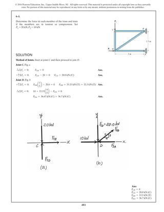
- 63. 543 © 2016 Pearson Education, Inc., Upper Saddle River, NJ. All rights reserved. This material is protected under all copyright laws as they currently exist. No portion of this material may be reproduced, in any form or by any means, without permission in writing from the publisher. SOLUTION Support Reactions. Referring to the FBD of the entire truss shown in Fig. a, ΣFx = 0; Dx - Bx - Ex + 2 = 0 (1) ΣFy = 0; Ay - 3 = 0 (2) ΣFz = 0; Dz + Bz - 4 = 0 (3) ΣMx = 0; 4(1.5) + 3(3 sin 60°) - Dz(3) = 0 (4) ΣMy = 0; 2(3 sin 60°) + 4(5) - Dz (5) - Ex (3 sin 60°) = 0 (5) ΣMz = 0; Dx (3) + Ay (5) - Ex (1.5) + 2(1.5) - 3(5) = 0 (6) Solving Eqs. (1) to (6) Ay = 3.00 kN Dz = 4.5981 kN Bz = -0.5981 kN Ex = 0.8490 kN Dx = -0.5755 kN Bx = 0.5755 kN Method of Joints. We will analyse the equilibrium of the joint at joint D first and then proceed to joint F. Joint D. Fig. b + cΣFz = 0; 4.5981 - FDF sin 60° = 0 FDF = 5.3094 kN (C) = 5.31 kN (C) Ans. 6–55. Determine the force in members EF, AF, and DF of the space truss and state if the members are in tension or compression. The truss is supported by short links at A, B, D, and E. z x y 3 m 3 m 4 kN 2 kN 3 kN 3 m 5 m F A E D B C
- 64. 544 © 2016 Pearson Education, Inc., Upper Saddle River, NJ. All rights reserved. This material is protected under all copyright laws as they currently exist. No portion of this material may be reproduced, in any form or by any means, without permission in writing from the publisher. Joint F. Fig. c ΣFx = 0; 2 - FEF - 5 234 FCF = 0 (7) ΣFy = 0; FAF cos 60° + 5.3094 cos 60° - 3 - FCF a 1.5 234 b = 0 (8) ΣFz = 0; 5.3094 sin 60° - 4 - FAF sin 60° - FCF a 3 sin 60° 234 b = 0 (9) Solving Eqs. (7), (8) and (9) FCF = 0 FEF = 2.00 kN (T) Ans. FAF = 0.6906 kN (T) = 0.691 kN (T) Ans. 6–55. Continued Ans: FDF = 5.31 kN (C) FEF = 2.00 kN (T) FAF = 0.691 kN (T)
- 65. 545 © 2016 Pearson Education, Inc., Upper Saddle River, NJ. All rights reserved. This material is protected under all copyright laws as they currently exist. No portion of this material may be reproduced, in any form or by any means, without permission in writing from the publisher. SOLUTION Support Reactions. Not required Method of Joints. Analysis of joint equilibrium will be in the sequence of joints D, C, B, A and F. Joint D. Fig. a ΣFx = 0; 20 - FDB a 4 5 b = 0 FDB = 25.0 kN (T) Ans. ΣFy = 0; 25.0 a 3 5 b - FDC = 0 FDC = 15.0 kN (T) Ans. ΣFz = 0; FDE - 12 = 0 FDE = 12.0 kN (C) Ans. Joint C. Fig. b ΣFx = 0; FCB = 0 Ans. ΣFy = 0; FCE a 1 25 b + 15.0 = 0 FCE = -1525 kN = 33.5 kN (C) Ans. ΣFz = 0; -FCF - a-1525ba 2 25 b = 0 FCF = 30.0 kN (T) Ans. Joint B. Fig. c ΣFy = 0; FBE a 1.5 215.25 b - 25.0 a 3 5 b = 0 FBE = 10215.25 kN (T) = 39.1 kN (T) Ans. ΣFx = 0; 25.0 a 4 5 b - a10215.25b a 2 215.25 b - FBF a 2 213 b = 0 FBF = 0 Ans. ΣFz = 0; -FBA - a10215.25b a 3 215.25 b = 0 FBA = -30.0 kN = 30.0 kN (C) Ans. *6–56. The space truss is used to support the forces at joints B and D. Determine the force in each member and state if the members are in tension or compression. C D E F B A 12 kN 20 kN 2 m 90Њ 3 m 2.5 m 1.5 m
- 66. 546 © 2016 Pearson Education, Inc., Upper Saddle River, NJ. All rights reserved. This material is protected under all copyright laws as they currently exist. No portion of this material may be reproduced, in any form or by any means, without permission in writing from the publisher. Joint A. Fig. d ΣFy = 0; FAE = 0 Ans. ΣFx = 0; FAF = 0 Ans. Joint F. Fig. e ΣFy = 0; FFE = 0 Ans. *6–56. Continued Ans: FDB = 25.0 kN (C) FDC = 15.0 kN (T) FDE = 12.0 kN (C) FCE = 33.5 kN (C) FCF = 30.0 kN (T) FBE = 39.1 kN (T) FBF = 0 FBA = 30.0 kN (C) FAE = 0 FAF = 0 FFE = 0
- 67. 547 © 2016 Pearson Education, Inc., Upper Saddle River, NJ. All rights reserved. This material is protected under all copyright laws as they currently exist. No portion of this material may be reproduced, in any form or by any means, without permission in writing from the publisher. 6–57. The space truss is supported by a ball-and-socket joint at D and short links at C and E. Determine the force in each member and state if the members are in tension or compression.Take and F2 = 5400j6 lb.F1 = 5-500k6 lb SOLUTION Joint F: Ans. Joint B: Ans. Ans. Ans. Joint A: Ans. Ans. Ans. Joint E: Ans. Ans.FEF = 300 lb (C) ©Fx = 0; FEF - 3 5 (500) = 0 ©Fz = 0; FDE = 0 FAE = 667 lb (C) ©Fy = 0; FAE - 4 5 (333.3) - 4 234 (583.1) = 0 FAD = 333 lb (T) ©Fz = 0; 3 234 (583.1) - 500 + 3 5 FAD = 0 FAC = 583.1 = 583 lb (T) ©Fx = 0; 300 - 3 234 FAC = 0 FAB = 300 lb (C) ©Fx = 0; FAB - 3 5 (500) = 0 FBE = 500 lb (T) ©Fy = 0; 400 - 4 5 FBE = 0 ©Fz = 0; FBC = 0 ©Fy = 0; FBF = 0 ©My = 0; Cz = 0 ©Fx = 0; Dx = 0 Cy = -400 lb ©Mz = 0; -Cy (3) - 400(3) = 0 3 ft4 ft 3 ft x y z C D E A B F F2 F1
- 68. 548 © 2016 Pearson Education, Inc., Upper Saddle River, NJ. All rights reserved. This material is protected under all copyright laws as they currently exist. No portion of this material may be reproduced, in any form or by any means, without permission in writing from the publisher. 6–57. Continued Joint C: ΣFx = 0; 3 234 (583.1) - FCD = 0 FCD = 300 lb (C) Ans. ΣFz = 0; FCF - 3 234 (583.1) = 0 FCF = 300 lb (C) Ans. ΣFy = 0; 4 234 (583.1) - 400 = 0 Check! Joint F: ΣFx = 0; 3 218 FDF - 300 = 0 FDF = 424 lb (T) Ans. ΣFz = 0; 3 218 (424.3) - 300 = 0 Check! Ans: FBF = 0 FBC = 0 FBE = 500 lb (T) FAB = 300 lb (C) FAC = 583 lb (T) FAD = 333 lb (T) FAE = 667 lb (C) FDE = 0 FEF = 300 lb (C) FCD = 300 lb (C) FCF = 300 lb (C) FDF = 424 lb (T)
- 69. 549 © 2016 Pearson Education, Inc., Upper Saddle River, NJ. All rights reserved. This material is protected under all copyright laws as they currently exist. No portion of this material may be reproduced, in any form or by any means, without permission in writing from the publisher. 6–58. SOLUTION Joint F: Ans. Joint B: Ans. Ans. Ans. Joint A: Ans. Ans. Ans. Joint E: Ans. Ans.FEF = 300 lb (C) ©Fx = 0; FEF - 3 5 (500) = 0 ©Fz = 0; FDE = 0 FAE = 367 lb (C) ©Fy = 0; FAE + 300 - 4 234 (971.8) = 0 FAD = 0 ©Fz = 0; 3 234 (971.8) - 500 + 3 5 FAD = 0 FAC = 971.8 = 972 lb (T) ©Fx = 0; 300 + 200 - 3 234 FAC = 0 FAB = 300 lb (C) ©Fx = 0; FAB - 3 5 (500) = 0 FBE = 500 lb (T) ©Fy = 0; 400 - 4 5 FBE = 0 ©Fz = 0; FBC = 0 FBF = 0 Cz = 200 lb ©My = 0; Cz (3) - 200(3) = 0 Cy = - 666.7 lb ©Mz = 0; -Cy (3) - 400(3) - 200(4) = 0 Dx = - 200 lb ©Fx = 0; Dx + 200 = 0 The space truss is supported by a ball-and-socket joint at D and short links at C and E. Determine the force in each member and state if the members are in tension or compression. Take and F2 = 5400j6 lb. F1 = 5200i + 300j - 500k6lb 3 ft4 ft 3 ft x y z C D E A B F F2 F1
- 70. 550 © 2016 Pearson Education, Inc., Upper Saddle River, NJ. All rights reserved. This material is protected under all copyright laws as they currently exist. No portion of this material may be reproduced, in any form or by any means, without permission in writing from the publisher. Joint C: Ans. Ans. Joint F: Ans.FDF = 424 lb (T) ©Fx = 0; 3 218 FDF - 300 = 0 ©Fy = 0; 4 234 (971.8) - 666.7 = 0 Check! FCF = 300 lb (C) ©Fz = 0; FCF - 3 234 (971.8) + 200 = 0 FCD = 500 lb (C) ©Fx = 0; 3 234 (971.8) - FCD = 0 6–58. Continued Ans: FBF = 0 FBC = 0 FBE = 500 lb (T) FAB = 300 lb (C) FAC = 972 lb (T) FAD = 0 FAE = 367 lb (C) FDE = 0 FEF = 300 lb (C) FCD = 500 lb (C) FCF = 300 lb (C) FDF = 424 lb (T)
- 71. 551 © 2016 Pearson Education, Inc., Upper Saddle River, NJ. All rights reserved. This material is protected under all copyright laws as they currently exist. No portion of this material may be reproduced, in any form or by any means, without permission in writing from the publisher. 6–59. Determine the force in each member of the space truss and state if the members are in tension or compression. The The truss is supported by ball-and-socket joints at A, B, and E. Set . Hint: The support reaction at E acts along member EC.Why? F = 5800j6 N F D A z 2 m x y B C E 5 m 1 m 2 m 1.5 m Ans: FAD = 686 N (T) FBD = 0 FCD = 615 N (C) FBC = 229 N (T) FAC = 343 N (T) FEC = 457 N (C)
- 72. 552 © 2016 Pearson Education, Inc., Upper Saddle River, NJ. All rights reserved. This material is protected under all copyright laws as they currently exist. No portion of this material may be reproduced, in any form or by any means, without permission in writing from the publisher. *6–60. Determine the force in each member of the space truss and state if the members are in tension or compression. The truss is supported by ball-and-socket joints at A, B, and E. Set . Hint: The support reaction at E acts along member EC.Why? F = 5-200i + 400j6 N F D A z 2 m x y B C E 5 m 1 m 2 m 1.5 m SOLUTION Joint D: Ans. Ans. Ans. Joint C: Ans. Ans. Ans.FEC = 295 N (C) ©Fz = 0; FEC - 2 27.25 (397.5) = 0 FAC = 221 N (T) ©Fy = 0; 1.5 27.25 (397.5) - FAC = 0 FBC = 148 N (T) ©Fx = 0; FBC - 1 27.25 (397.5) = 0 FCD = 397.5 = 397 N (C) FBD = 186 N (T) FAD = 343 N (T) ©Fz = 0; - 2 3 FAD - 2 231.25 FBD + 2 27.25 FCD = 0 ©Fy = 0; - 2 3 FAD + 1.5 231.25 FBD - 1.5 27.25 FCD + 400 = 0 ©Fx = 0; - 1 3 FAD + 5 231.25 FBD + 1 27.25 FCD - 200 = 0
- 73. 553 © 2016 Pearson Education, Inc., Upper Saddle River, NJ. All rights reserved. This material is protected under all copyright laws as they currently exist. No portion of this material may be reproduced, in any form or by any means, without permission in writing from the publisher. 6–61. Determine the force required to hold the 100-lb weight in equilibrium. P SOLUTION Equations of Equilibrium: Applying the force equation of equilibrium along the y axis of pulley A on the free - body diagram, Fig. a, Applying to the free - body diagram of pulley B, Fig. b, From the free - body diagram of pulley C, Fig. c, Ans.+ c©Fy = 0; 2P - 25 = 0 P = 12.5 lb + c©Fy = 0; 2TB - 50 = 0 TB = 25 lb ©Fy = 0 + c ©Fy = 0; 2TA - 100 = 0 TA = 50 lb P A B C D Ans: P = 12.5 lb
- 74. 554 © 2016 Pearson Education, Inc., Upper Saddle River, NJ. All rights reserved. This material is protected under all copyright laws as they currently exist. No portion of this material may be reproduced, in any form or by any means, without permission in writing from the publisher. 6–62. SOLUTION Equations of Equilibrium: a) Ans. b) Ans. c) Ans.P = 11.1 lb 3P - 33.33 = 0+ c ©Fy = 0; P¿ = 33.33 lb 3P¿ - 100 = 0+ c ©Fy = 0; P = 33.3 lb 3P - 100 = 0+ c ©Fy = 0; P = 25.0 lb 4P - 100 = 0+ c ©Fy = 0; In each case, determine the force P required to maintain equilibrium.The block weighs 100 lb. P (a) (b) (c) P P Ans: P = 25.0 lb P = 33.3 lb P = 11.1 lb
- 75. 555 © 2016 Pearson Education, Inc., Upper Saddle River, NJ. All rights reserved. This material is protected under all copyright laws as they currently exist. No portion of this material may be reproduced, in any form or by any means, without permission in writing from the publisher. 6–63. Determine the force required to hold the 50-kg mass in equilibrium. P SOLUTION Equations of Equilibrium: Applying the force equation of equilibrium along the y axis of each pulley. Ans. Substituting Eqs.(1) and (2) into Eq.(3) and solving for P, Ans.P = 18.9 N 2P + 2(3P) + 2(9P) = 50(9.81) + c©Fy = 0; 2P + 2R + 2T - 50(9.81) = 0 + c©Fy = 0; T - 3R = 0; T = 3R = 9P + c©Fy = 0; R - 3P = 0; R = 3P P A B C Ans: P = 18.9 N
- 76. 556 © 2016 Pearson Education, Inc., Upper Saddle River, NJ. All rights reserved. This material is protected under all copyright laws as they currently exist. No portion of this material may be reproduced, in any form or by any means, without permission in writing from the publisher. *6–64. SOLUTION Equations of Equilibrium: Applying the force equation of equilibrium along the y axis of pulley A on the free - body diagram, Fig. a, Using the above result and writing the force equation of equilibrium along the axis of pulley C on the free - body diagram in Fig. b, Ans.©Fy¿ = 0; 735.75 - 2P = 0 P = 367.88 N = 368 N y¿ + c ©Fy = 0; 2TA - 150(9.81) = 0 TA = 735.75 N Determine the force required to hold the 150-kg crate in equilibrium. P P A B C Ans: P = 368 N
- 77. 557 © 2016 Pearson Education, Inc., Upper Saddle River, NJ. All rights reserved. This material is protected under all copyright laws as they currently exist. No portion of this material may be reproduced, in any form or by any means, without permission in writing from the publisher. SOLUTION Free Body Diagram. The frame will be dismembered into members BC and AC. The solution will be very much simplified if one recognizes that member AC is a two force member. The FBDs of member BC and pin A are shown in Figs. a and b, respectively. Equations of Equilibrium. Consider the equilibrium of member BC, Fig. a, a+ΣMB = 0; 2(4)(2) - FAC a 3 5 b(4) = 0 FAC = 6.6667 kN a+ΣMC = 0; Bx (4) - 2(4)(2) = 0 Bx = 4.00 kN Ans. + cΣFy = 0; 6.6667 a 4 5 b - By = 0 By = 5.333 kN = 5.33 kN Ans. Then, the equilibrium of pin A gives S+ ΣFx = 0; Ax - 6.6667 a 3 5 b = 0 Ax = 4.00 kN Ans. + cΣFy = 0; Ay - 6.6667 a 4 5 b = 0 Ay = 5.333 kN = 5.33 kN Ans. 6–65. Determine the horizontal and vertical components of force that pins A and B exert on the frame. 4 m 3 m 2 kN/m A C B Ans: Bx = 4.00 kN By = 5.33 kN Ax = 4.00 kN Ay = 5.33 kN
- 78. 558 © 2016 Pearson Education, Inc., Upper Saddle River, NJ. All rights reserved. This material is protected under all copyright laws as they currently exist. No portion of this material may be reproduced, in any form or by any means, without permission in writing from the publisher. SOLUTION Free Body Diagram. The assembly will be dismembered into member AC, BD and pulley E. The solution will be very much simplified if one recognizes that member BD is a two force member.The FBD of pulley E and member AC are shown in Fig. a and b respectively. Equations of Equilibrium. Consider the equilibrium of pulley E, Fig. a, + cΣFy = 0; 2T - 12 = 0 T = 6.00 kN Then, the equilibrium of member AC gives a+ΣMA = 0; FBD a 4 5 b(1.5) + 6(0.3) - 6(3) - 6(3.3) = 0 FBD = 30.0 kN S+ ΣFx = 0; Ax - 30.0 a 3 5 b - 6 = 0 Ax = 24.0 kN Ans. + cΣFy = 0; 30.0 a 4 5 b - 6 - 6 - Ay = 0 Ay = 12.0 kN Ans. Thus, FA = 2Ax 2 + Ay 2 = 224.02 + 12.02 = 26.83 kN = 26.8 kN FB = FBD = 30.0 kN Dx = 3 5 (30) = 18.0 kN Ans. Dy = 4 5 (30) = 24.0 kN Ans. 6–66. Determine the horizontal and vertical components of force at pins A and D. 1.5 m D A B C E 1.5 m 0.3 m 12 kN 2 m Ans: Ax = 24.0 kN Ay = 12.0 kN Dx = 18.0 kN Dy = 24.0 kN
- 79. 559 © 2016 Pearson Education, Inc., Upper Saddle River, NJ. All rights reserved. This material is protected under all copyright laws as they currently exist. No portion of this material may be reproduced, in any form or by any means, without permission in writing from the publisher. 6–67. SOLUTION a Ans. Ans. a Ans.NC = 15.0 lb +©MB = 0; -NC (4) + 120(0.5) = 0 + c©Fy = 0; Ay = 0 :+ ©Fx = 0; Ax = 120 lb Dx = 120 lb +©MA = 0; -60 + Dx (0.5) = 0 Determine the force that the smooth roller C exerts on member AB. Also, what are the horizontal and vertical components of reaction at pin A? Neglect the weight of the frame and roller. C 0.5 ft 3 ft A 60 lb ft 4 ft B D Ans: Ax = 120 lb Ay = 0 NC = 15.0 lb
- 80. 560 © 2016 Pearson Education, Inc., Upper Saddle River, NJ. All rights reserved. This material is protected under all copyright laws as they currently exist. No portion of this material may be reproduced, in any form or by any means, without permission in writing from the publisher. *6–68. SOLUTION For segment BD: a Ans. Ans. Ans. For segment ABC: a Ans. Ans. Ans. For segment DEF: a Ans. Ans. Ans.+ c©Fy = 0; -Ey + 135 - 2(15) - 30 = 0 Ey = 75 kip :+ ©Fx = 0; Ex = 0 + ©Mg = 0; -Fy(5) + 2(15)(7.5) + 30(15) = 0 Fy = 135 kip + c©Fy = 0; -Ay + 135 - 2(15) - 30 = 0 Ay = 75 kip :+ ©Fx = 0; Ax = 0 + ©MA = 0; Cy (5) - 2(15)(7.5) - 30(15) = 0 Cy = 135kip + c©Fy = 0; Dy + 30 - 2(30) = 0 Dy = 30 kip :+ ©Fx = 0; Dx = 0 + ©MD = 0; 2(30)(15) - By (30) = 0 By = 30 kip The bridge frame consists of three segments which can be considered pinned at A, D, and E, rocker supported at C and F, and roller supported at B. Determine the horizontal and vertical components of reaction at all these supports due to the loading shown. 15 ft 20 ft 5 ft 5 ft 15 ft 2 kip/ft 30 ft A B C F D E Ans: By = 30 kip Dx = 0 Dy = 30 kip Cy = 135 kip Ay = 75 kip Fy = 135 kip Ex = 0 Ey = 75 kip
- 81. 561 © 2016 Pearson Education, Inc., Upper Saddle River, NJ. All rights reserved. This material is protected under all copyright laws as they currently exist. No portion of this material may be reproduced, in any form or by any means, without permission in writing from the publisher. 6–69. Determine the reactions at supports A and B. SOLUTION Member DB: a Ans. Ans. Member AC: Ans. Ans. a Ans.MA = 43.2 kip # ft +©MA = 0; MA - 3(6) - 3.50 a 3 5 b(12) = 0 Ay = 5.10 kip + c ©Fy = 0; Ay - 3 - 3.50 a 3 5 b = 0 Ax = 2.80 kip :+ ©Fx = 0; Ax - 3.50a 4 5 b = 0 By = 1.05 kip + c ©Fy = 0; By - 3.15 + 3.50a 3 5 b = 0 Bx = 2.80 kip :+ ©Fx = 0; -Bx + 3.50a 4 5 b = 0 FCD = 3.50 kip +©MB = 0; 3.15 (6) - FCDa 3 5 b (9) = 0 6 ft 500 lb/ft 6 ft 8 ft 9 ft 700 lb/ft 6 ft A C D B Ans: Bx = 2.80 kip By = 1.05 kip Ax = 2.80 kip Ay = 5.10 kip MA = 43.2 kip # ft
- 82. 562 © 2016 Pearson Education, Inc., Upper Saddle River, NJ. All rights reserved. This material is protected under all copyright laws as they currently exist. No portion of this material may be reproduced, in any form or by any means, without permission in writing from the publisher. SOLUTION Free Body Diagram. The solution will be very much simplified if one realizes that member AB is a two force member. Also, the tension in the cable is equal to the weight of the cylinder and is constant throughout the cable. Equations of Equilibrium. Consider the equilibrium of member BC by referring to its FBD, Fig. a, a+ΣMC = 0; FAB a 3 5 b(2) + 75(9.81)(0.3) - 75(9.81)(2.8) = 0 FAB = 1532.81 N a+ΣMB = 0; Cy (2) + 75(9.81)(0.3) - 75(9.81)(0.8) = 0 Cy = 183.94 N = 184 N Ans. S+ ΣFx = 0; 1532.81a 4 5 b - 75(9.81) - Cx = 0 Cx = 490.5 N Ans. Thus, FB = FAB = 1532.81 N Bx = 4 5 (1532.81) = 1226.25 N = 1.23 kN Ans. By = 3 5 (1532.81) = 919.69 N = 920 kN Ans. 6–70. Determine the horizontal and vertical components of force at pins B and C.The suspended cylinder has a mass of 75 kg. A BC 1.5 m 0.3 m 2 m 0.5 m Ans: Cy = 184 N Cx = 490.5 N Bx = 1.23 kN By = 920 kN
- 83. 563 © 2016 Pearson Education, Inc., Upper Saddle River, NJ. All rights reserved. This material is protected under all copyright laws as they currently exist. No portion of this material may be reproduced, in any form or by any means, without permission in writing from the publisher. SOLUTION Free Body Diagram. The compound beam is being dismembered into members AB, BD and DE of which their respective FBDs are shown in Fig. a, b and c. Equations of Equilibrium. Equilibrium of member DE will be considered first by referring to Fig. c. a+ΣMD = 0; NE(6) - 12(9) = 0 NE = 18.0 kN Ans. a+ΣME = 0; Dy(6) - 12(3) = 0 Dy = 6.00 kN S+ ΣFx = 0; Dx = 0 Next, member BD, Fig. b. a+ΣMC = 0; 6.00(2) + 3(6)(1) - By(4) = 0 By = 7.50 kN a+ΣMB = 0; NC(4) + 6.00(6) - 3(6)(3) = 0 NC = 4.50 kN Ans. S+ ΣFx = 0; Bx = 0 Finally, member AB, Fig. a S+ ΣFx = 0; Ax = 0 Ans. + cΣFy = 0; Ay - 7 -50 = 0 Ay = 7.50 kN Ans. a+ΣMA = 0; MA - 7.50(3) = 0 MA = 22.5 kN # m Ans. 6–71. Determine the reactions at the supports A, C, and E of the compound beam. 4 m 3 m3 m 6 m 2 m A DB EC 3 kN/m 12 kN Ans: NE = 18.0 kN NC = 4.50 kN Ax = 0 Ay = 7.50 kN MA = 22.5 kN # m
- 84. 564 © 2016 Pearson Education, Inc., Upper Saddle River, NJ. All rights reserved. This material is protected under all copyright laws as they currently exist. No portion of this material may be reproduced, in any form or by any means, without permission in writing from the publisher. SOLUTION Free Body Diagram. The frame is being dismembered into members AC and BC of which their respective FBDs are shown in Fig. a and b. Equations of Equilibrium. Write the moment equation of equilibrium about point A for member AC, Fig. a and point B for member BC, Fig. b. a+ΣMA = 0; Cy a 2 tan 60° b + Cx (2) - 200 a 2 sin 60° ba 1 sin 60° b = 0 (1) a+ΣMB = 0; Cy(2) - Cx(2) + 800(2) = 0 (2) Solving Eqs. (1) and (2) Cy = -338.12 N Cx = 461.88 N The negative sign indicates that Cy acts in the sense opposite to that shown in the FBD write the force equation of equilibrium for member AC, Fig. a, S+ ΣFx = 0; Ax + 200 a 2 sin 60° b sin 60° - 461.88 = 0 Ax = 61.88 N + cΣFy = 0; Ay + (-338.12) - 200 a 2 sin 60° b cos 60° = 0 Ay = 569.06 N Also, for member BC, Fig. b S+ ΣFx = 0; Bx + 461.88 - 800 = 0 Bx = 338.12 N + cΣFy = 0; -By - (-338.12) = 0 By = 338.12 N Thus, FC = 2Cx 2 + Cy 2 = 2461.882 + (-338.12)2 = 572.41 N = 572 N Ans. FA = 2Ax 2 + Ay 2 = 261.882 + 569.062 = 572.41 N = 572 N Ans. FB = 2Bx 2 + By 2 = 2338.122 + 338.122 = 478.17 N = 478 N Ans. *6–72. Determine the resultant force at pins A, B, and C on the three-member frame. 200 N/ m 60Њ 2 m 800 N 2 m B C A Ans: FC = 572 N FA = 572 N FB = 478 N
- 85. 565 © 2016 Pearson Education, Inc., Upper Saddle River, NJ. All rights reserved. This material is protected under all copyright laws as they currently exist. No portion of this material may be reproduced, in any form or by any means, without permission in writing from the publisher. SOLUTION Free Body Diagram. The solution will be very much simplified if one realizes that member CD is a two force member. Equation of Equilibrium. Consider the equilibrium of member BD, Fig. b S+ ΣFx = 0; FCD = 0 a+ΣMB = 0; 1 2 (900)(6)(4) - NE (3) = 0 NE = 3600 N = 3.60 kN Ans. a+ΣME = 0; 1 2 (900)(6)(1) - NB (3) = 0 NB = 900 N Ans. Then the equilibrium of member AC gives S+ ΣFx = 0; Ax = 0 Ans. + cΣFy = 0; Ay - 1 2 (900)(6) = 0 Ay = 2700 N = 2.70 kN Ans. a+ΣMA = 0; MA - 1 2 (900)(6)(3) = 0 MA = 8100 N # m = 8.10 kN # m Ans. 6–73. Determine the reactions at the supports at A, E, and B of the compound beam. 3 m 900 N/m 900 N/m 4 m3 m A C D B 3 m 3 m E Ans: NE = 3.60 kN NB = 900 N Ax = 0 Ay = 2.70 kN MA = 8.10 kN # m
- 86. 566 © 2016 Pearson Education, Inc., Upper Saddle River, NJ. All rights reserved. This material is protected under all copyright laws as they currently exist. No portion of this material may be reproduced, in any form or by any means, without permission in writing from the publisher. 6–74. The wall crane supports a load of 700 lb. Determine the horizontal and vertical components of reaction at the pins A and D. Also, what is the force in the cable at the winch W? SOLUTION Pulley E: Ans. Member ABC: a Ans. Ans. At D: Ans. Ans.Dy = 2409 sin 45° = 1.70 kip Dx = 2409 cos 45° = 1703.1 lb = 1.70 kip Ax = 1.88 kip -Ay - 2409 cos 45° - 350 cos 60° + 350 - 350 = 0+ : ©Fx = 0; Ay = 700 lb -Ay + 2409 sin 45° - 350 sin 60° - 700 = 0+ c©Fy = 0; TBD = 2409 lb TBD sin 45°(4) - 350 sin 60°(4) # 700 (8) = 0+©MA = 0; T = 350 lb 2T - 700 = 0+ c©Fy = 0; 4 ft D A B C E W 4 ft 700 lb 60 4 ft Ans: T = 350 lb Ay = 700 lb Ax = 1.88 kip Dx = 1.70 kip Dy = 1.70 kip
- 87. 567 © 2016 Pearson Education, Inc., Upper Saddle River, NJ. All rights reserved. This material is protected under all copyright laws as they currently exist. No portion of this material may be reproduced, in any form or by any means, without permission in writing from the publisher. 6–75. The wall crane supports a load of 700 lb. Determine the horizontal and vertical components of reaction at the pins A and D. Also, what is the force in the cable at the winch W? The jib ABC has a weight of 100 lb and member BD has a weight of 40 lb. Each member is uniform and has a center of gravity at its center. 4 ft D A B C E W 4 ft 700 lb 60 4 ft SOLUTION Pulley E: Ans. Member ABC: a Ans. (1) Member DB: a Ans. Ans. From Eq. (1) Ans.Ax = 2.00 kip Dy = 1843.1 = 1.84 kip + c ©Fy = 0; Dy - 40 - 1803.1 = 0 Dx = 1.82 kip :+ ©Fx = 0; -Dx + 1823.1 = 0 Bx = 1823.1 lb + ©MD = 0; -40 (2) - 1803.1 (4) + Bx (4) = 0 Ax = Bx + 175 :+ ©Fx = 0; Ax - 350 cos 60° - Bx + 350 - 350 = 0 Ay = 700 lb + c©Fy = 0; -Ay - 350 sin 60° - 100 - 700 + 1803.1 = 0 By = 1803.1 lb + ©MA = 0; By (4) - 700(8) - 100(4) - 350 sin 60° (4) = 0 T = 350 lb + c ©Fy = 0; 2T - 700 = 0 Ans: T = 350 lb Ay = 700 lb Dx = 1.82 kip Dy = 1.84 kip Ax = 2.00 kip
- 88. 568 © 2016 Pearson Education, Inc., Upper Saddle River, NJ. All rights reserved. This material is protected under all copyright laws as they currently exist. No portion of this material may be reproduced, in any form or by any means, without permission in writing from the publisher. SOLUTION Free Body Diagram. The frame will be dismembered into members AD, EF, CD and BC. The solution will be very much simplified if one realizes that members CD and EF are two force member. Therefore, only the FBD of members AD and BC, Fig. a and b respectively, need to be drawn Equations of Equilibrium. Write the moment equations of equilibrium about point A for member AD, Fig. a, and point B for member BC, Fig. b. a+ΣMA = 0; FEF a 4 5 b(3) - FCD (4.5) - 400 (4.5)(2.25) = 0 (1) a+ΣMB = 0; -FEF a 4 5 b(1.5) + FCD (4.5) = 0 (2) Solving Eqs. (1) and (2) FEF = 3375 N FCD = 900 N Write the force equation of equilibrium for member AD, Fig. a, S+ ΣFx = 0; Ax + 400(4.5) + 900 - 3375 a 4 5 b = 0 Ax = 0 Ans. + cΣFy = 0; 3375 a 3 5 b - Ay = 0 Ay = 2025 N = 2.025 kN Ans. Also, for member BC, Fig. b S+ ΣFx = 0; 3375a 4 5 b - 900 - Bx = 0 Bx = 1800 N = 1.80 kN Ans. + cΣFy = 0; By - 3375a 3 5 b = 0 By = 2025 N = 2.025 kN Ans. *6–76. Determine the horizontal and vertical components of force which the pins at A and B exert on the frame. 400 N/m 1.5 m 2 m 3 m 3 m 1.5 m A F E D B C Ans: Ax = 0 Ay = 2.025 kN Bx = 1.80 kN By = 2.025 kN
- 89. 569 © 2016 Pearson Education, Inc., Upper Saddle River, NJ. All rights reserved. This material is protected under all copyright laws as they currently exist. No portion of this material may be reproduced, in any form or by any means, without permission in writing from the publisher. 6–77. SOLUTION Member AC: a Ans. Ans. Member BDE: a Ans. Ans. Ans.Ey = 1608 lb = 1.61 kip + c ©Fy = 0; -500 - 120 a 3 5 b + 2180 - Ey = 0 Ex = 96 lb :+ ©Fx = 0; -Ex + 120a 4 5 b = 0 Dy = 2180 lb = 2.18 kip +©Mg = 0; 500 (8) + 120a 3 5 b (5) - Dy (2) = 0 Ay = 72 lb + c ©Fy = 0; -Ay + 120a 3 5 b = 0 Ax = 96 lb :+ ©Fx = 0; Ax - 120a 4 5 b = 0 NC = 120 lb +©MA = 0; NC (5) - 600 = 0 The two-member structure is connected at C by a pin, which is fixed to BDE and passes through the smooth slot in member AC. Determine the horizontal and vertical components of reaction at the supports. 3 ft 3 ft 2 ft 4 ft A B C D E 600 lb ft 500 lb Ans: Ax = 96 lb Ay = 72 lb Dy = 2.18 kip Ex = 96.0 lb Ey = 1.61 kip
- 90. 570 © 2016 Pearson Education, Inc., Upper Saddle River, NJ. All rights reserved. This material is protected under all copyright laws as they currently exist. No portion of this material may be reproduced, in any form or by any means, without permission in writing from the publisher. SOLUTION Free Body Diagram. The compound beam will be dismembered into members ABD and CD of which their respective FBD are shown in Fig. a and b. Equations of Equilibrium. First, consider the equilibrium of member CD, Fig. b, a+ΣMD = 0; NC (3) - 2(3)(1.5) = 0 NC = 3.00 kN Ans. a+ΣMC = 0; 2(3)(1.5) - Dy (3) = 0 Dy = 3.00 kN Ans. S+ ΣFx = 0; Dx = 0 Next, the equilibrium of member ABD gives, a+ΣMB = 0; 2(9)(1.5) - 3.00(3) - NA(6) = 0 NA = 3.00 kN Ans. a+ΣMA = 0; By (6) - 2(9)(4.5) - 3.00(9) = 0 By = 18.0 kN Ans. S+ ΣFx = 0; Bx = 0 Ans. 6–78. The compound beam is pin supported at B and supported by rockers at A and C.There is a hinge (pin) at D.Determine the reactions at the supports. C DB A 6 m 3 m 2 kN/m 3 m Ans: NC = 3.00 kN NA = 3.00 kN By = 18.0 kN Bx = 0
- 91. 571 © 2016 Pearson Education, Inc., Upper Saddle River, NJ. All rights reserved. This material is protected under all copyright laws as they currently exist. No portion of this material may be reproduced, in any form or by any means, without permission in writing from the publisher. 6–79. The toggle clamp is subjected to a force F at the handle. Determine the vertical clamping force acting at E. 1.5 a 1.5 a 60 a/2 a/2 a/2E C D F B A SOLUTION Free Body Diagram: The solution for this problem will be simplified if one realizes that member CD is a two force member. Equations of Equilibrium: From FBD (a), a From (b), a Ans.FE = 3.64F 5.464F1a2 - FE 11.5a2 = 0+ ©MA = 0; Bx = 5.464F Bx - 10.93 sin 30° = 0:+ ©Fx = 0; FCD = 10.93F FCD cos 30°a a 2 b - FCD sin 30°a a 2 b - F12a2 = 0+ ©MB = 0; Ans: NC = ND = 2 lb
- 92. 572 © 2016 Pearson Education, Inc., Upper Saddle River, NJ. All rights reserved. This material is protected under all copyright laws as they currently exist. No portion of this material may be reproduced, in any form or by any means, without permission in writing from the publisher. *6–80. When a force of 2 lb is applied to the handles of the brad squeezer, it pulls in the smooth rod AB. Determine the force P exerted on each of the smooth brads at C and D. SOLUTION Equations of Equilibrium: Applying the moment equation of equilibrium about point E to the free-body diagram of the lower handle in Fig.a,we have Using the result of FAB and considering the free-body diagram in Fig. b, (1) (2) Solving Eqs. (1) and (2) yields Ans.NC = ND = 2 lb 4 - NC - ND = 0©Fx = 0;: + NC = ND NC(1.5) - ND(1.5) = 0+©MB = 0; FAB = 4 lb 2(2) - FAB(1) = 0+©ME = 0; A C D 2 lb 1 in. 2 lb 2 in. 2 in. 0.25 in. 1.5 in. 1.5 in. E B P P Ans: NC = ND = 2 1b