More Related Content
Similar to Beam reactions and structural analysis
Similar to Beam reactions and structural analysis (16)
Beam reactions and structural analysis
- 1. 397
© 2016 Pearson Education, Inc., Upper Saddle River, NJ. All rights reserved. This material is protected under all copyright laws as they currently
exist. No portion of this material may be reproduced, in any form or by any means, without permission in writing from the publisher.
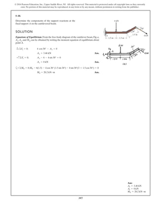
5–10.
Determine the components of the support reactions at the
fixed support A on the cantilevered beam.
1.5 m
1.5 m
30Њ
30Њ
4 kN
6 kN
A
1.5 m
SOLUTION
Equations of Equilibrium: From the free-body diagram of the cantilever beam, Fig. a,
Ax, Ay, and MA can be obtained by writing the moment equation of equilibrium about
point A.
Ans.
Ans.
Ans.MA = 20.2 kN # m
- 4 sin 30°(3 + 1.5 cos 30°) = 0MA - 6(1.5) - 4 cos 30° (1.5 sin 30°)a+ ©MA = 0;
Ay = 8 kN
Ay - 6 - 4 sin 30° = 0+ c©Fy = 0;
Ax = 3.46 kN
4 cos 30° - Ax = 0©Fx = 0;:
+
Ans:
Ax = 3.46 kN
Ay = 8 kN
MA = 20.2 kN # m
- 2. 398
© 2016 Pearson Education, Inc., Upper Saddle River, NJ. All rights reserved. This material is protected under all copyright laws as they currently
exist. No portion of this material may be reproduced, in any form or by any means, without permission in writing from the publisher.
Ans:
NA = 750 N
By = 600 N
Bx = 450 N
Solution
Equations of Equilibrium. NA and By can be determined directly by writing the
moment equations of equilibrium about points B and A, respectively, by referring to
the beam’s FBD shown in Fig. a.
a+ΣMB = 0;
1
2
(400)(6)(3) - NA a
4
5
b(6) = 0
NA = 750 N Ans.
a+ΣMA = 0; By(6) -
1
2
(400)(6)(3) = 0
By = 600 N Ans.
Using the result of NA to write the force equation of equilibrium along the x axis,
S+ ΣFx = 0; 750a
3
5
b - Bx = 0
Bx = 450 N Ans.
5–11.
Determine the reactions at the supports. 400 N/m
3 m
3
4
5
3 m
A
B
- 3. 399
© 2016 Pearson Education, Inc., Upper Saddle River, NJ. All rights reserved. This material is protected under all copyright laws as they currently
exist. No portion of this material may be reproduced, in any form or by any means, without permission in writing from the publisher.
*5–12.
6 m
A
B
4 kN
2 m
30Њ
Determine the horizontal and vertical components of
reaction at the pin A and the reaction of the rocker B on
the beam.
SOLUTION
Equations of Equilibrium: From the free-body diagram of the beam, Fig. a, NB can
be obtained by writing the moment equation of equilibrium about point A.
Ans.
Using this result and writing the force equations of equilibrium along the x and
y axes, we have
Ans.
Ans.Ay = 1.00 kN
Ay + 3.464 cos 30° - 4 = 0+ c ©Fy = 0;
Ax = 1.73 kN
Ax - 3.464 sin 30° = 0©Fx = 0;:
+
NB = 3.464 kN = 3.46 kN
NB cos 30°(8) - 4(6) = 0a+©MA = 0;
Ans:
NB = 3.46 kN
Ax = 1.73 kN
Ay = 1.00 kN
- 4. 400
© 2016 Pearson Education, Inc., Upper Saddle River, NJ. All rights reserved. This material is protected under all copyright laws as they currently
exist. No portion of this material may be reproduced, in any form or by any means, without permission in writing from the publisher.
Ans:
NA = 2.175 kN
By = 1.875 kN
Bx = 0
Solution
Equations of Equilibrium. NA and By can be determined directly by writing the
moment equations of equilibrium about points B and A, respectively, by referring to
the FBD of the beam shown in Fig. a.
a+ΣMB = 0; 600(6)(3) +
1
2
(300)(3)(5) - NA(6) = 0
NA = 2175 N = 2.175 kN Ans.
a+ΣMA = 0; By(6) -
1
2
(300)(3)(1) - 600(6)(3) = 0
By = 1875 N = 1.875 kN Ans.
Also, Bx can be determined directly by writing the force equation of equilibrium
along the x axis.
S+ ΣFx = 0; Bx = 0 Ans.
5–13.
Determine the reactions at the supports.
3 m 3 m
A B
900 N/m
600 N/m
- 5. 401
© 2016 Pearson Education, Inc., Upper Saddle River, NJ. All rights reserved. This material is protected under all copyright laws as they currently
exist. No portion of this material may be reproduced, in any form or by any means, without permission in writing from the publisher.
Ans:
NA = 3.33 kN
Bx = 2.40 kN
By = 133 N
Solution
Equations of Equilibrium. NA can be determined directly by writing the moment
equation of equilibrium about point B by referring to the FBD of the beam shown
in Fig. a.
a+ΣMB = 0; 800(5)(2.5) - NA(3) = 0
NA = 3333.33 N = 3.33 kN Ans.
Using this result to write the force equations of equilibrium along the x and y axes,
S+ ΣFx = 0; Bx - 800(5)a
3
5
b = 0
Bx = 2400 N = 2.40 kN Ans.
+ c ΣFy = 0; 3333.33 - 800(5)a
4
5
b - By = 0
By = 133.33 N = 133 N Ans.
5–14.
Determine the reactions at the supports.
B
A
3 m
800 N/m
3 m
1 m
- 6. 402
© 2016 Pearson Education, Inc., Upper Saddle River, NJ. All rights reserved. This material is protected under all copyright laws as they currently
exist. No portion of this material may be reproduced, in any form or by any means, without permission in writing from the publisher.
Ans:
Ay = 5.00 kN
NB = 9.00 kN
Ax = 5.00 kN
Solution
Equations of Equilibrium. Ay and NB can be determined by writing the moment
equations of equilibrium about points B and A, respectively, by referring to the FBD
of the truss shown in Fig. a.
a+ΣMB = 0; 8(2) + 6(4) - 5(2) - Ay(6) = 0
Ay = 5.00 kN Ans.
a+ΣMA = 0; NB(6) - 8(4) - 6(2) - 5(2) = 0
NB = 9.00 kN Ans.
Also, Ax can be determined directly by writing the force equation of equilibrium
along x axis.
S+ ΣFx = 0; 5 - Ax = 0 Ax = 5.00 kN Ans.
5–15.
Determine the reactions at the supports.
A B
2 m 2 m 2 m
2 m
6 kN
5 kN
8 kN
- 7. 403
© 2016 Pearson Education, Inc., Upper Saddle River, NJ. All rights reserved. This material is protected under all copyright laws as they currently
exist. No portion of this material may be reproduced, in any form or by any means, without permission in writing from the publisher.
*5–16.
Determine the tension in the cable and the horizontal and
vertical components of reaction of the pin A. The pulley at
D is frictionless and the cylinder weighs 80 lb.
SOLUTION
Equations of Equilibrium: The tension force developed in the cable is the same
throughout the whole cable. The force in the cable can be obtained directly by
summing moments about point A.
a
Ans.
Ans.
Ans.Ay = 61.3 lb
74.583 + 74.583
2
25
- 80 - By = 0+ c ©Fy = 0;
Ax = 33.4 lb
Ax - 74.583¢
1
25
≤ = 0:+ ©Fx = 0;
T = 74.583 lb = 74.6 lb
T152 + T¢
2
25
≤1102 - 801132 = 0+ ©MA = 0;
BA
D
C
5 ft 5 ft
2
1
3 ft
Ans:
T = 74.6 lb
Ax = 33.4 lb
Ay = 61.3 lb
- 8. 404
© 2016 Pearson Education, Inc., Upper Saddle River, NJ. All rights reserved. This material is protected under all copyright laws as they currently
exist. No portion of this material may be reproduced, in any form or by any means, without permission in writing from the publisher.
5–17.
The man attempts to support the load of boards having a
weight W and a center of gravity at G. If he is standing on a
smooth floor, determine the smallest angle at which he can
hold them up in the position shown. Neglect his weight.
u
SOLUTION
a
As becomes smaller, so that,
Ans.u = 41.4°
W(3 - 4 cos u) = 0
NA : 0u
+©MB = 0; -NA (3.5) + W(3 - 4 cos u) = 0
A B
G
4 ft
4 ft
3 ft0.5 ft
u
Ans:
u = 41.4°
- 9. 405
© 2016 Pearson Education, Inc., Upper Saddle River, NJ. All rights reserved. This material is protected under all copyright laws as they currently
exist. No portion of this material may be reproduced, in any form or by any means, without permission in writing from the publisher.
5–18.
Determine the components of reaction at the supports A and
B on the rod.
A
B
P
L––
2
L––
2
SOLUTION
Equations of Equilibrium: Since the roller at offers no resistance to vertical
movement, the vertical component of reaction at support is equal to zero. From
the free-body diagram, , , and can be obtained by writing the force
equations of equilibrium along the and axes and the moment equation of
equilibrium about point , respectively.
Ans.
Ans.
Ans.MA =
PL
2
Pa
L
2
b - MA = 0a+ ©MB = 0;
By = P
By - P = 0+c ©Fy = 0;
Ax = 0©Fx = 0;:
+
B
yx
MAByAx
A
A
Ans:
Ax = 0
By = P
MA =
PL
2
- 10. 406
© 2016 Pearson Education, Inc., Upper Saddle River, NJ. All rights reserved. This material is protected under all copyright laws as they currently
exist. No portion of this material may be reproduced, in any form or by any means, without permission in writing from the publisher.
5–19.
The man has a weight W and stands at the center of the
plank. If the planes at A and B are smooth, determine the
tension in the cord in terms of W and u.
SOLUTION
a
(1)
(2)
Solving Eqs. (1) and (2) yields:
Ans.
NB =
W
2
cos u
T =
W
2
sin u
+ c©Fy = 0; Tsin u+NB cos u +
W
2
- W= 0
:+ ©Fx = 0; Tcos u-NB sin u = 0
+©MB = 0; Wa
L
2
cos f b -NA(Lcos f ) = 0 NA =
W
2 A
B
L
uf
Ans:
T =
W
2
sin u
- 11. 407
© 2016 Pearson Education, Inc., Upper Saddle River, NJ. All rights reserved. This material is protected under all copyright laws as they currently
exist. No portion of this material may be reproduced, in any form or by any means, without permission in writing from the publisher.
*5–20.
A uniform glass rod having a length L is placed in the smooth
hemispherical bowl having a radius r. Determine the angle of
inclination for equilibrium.u
SOLUTION
By observation .
Equilibrium:
a
Take the positive root
Ans.u = cos-1
¢
L + 2L2
+ 128r2
16r
≤
cos u =
L + 2L2
+ 128r2
16r
cos u =
L ; 2L2
+ 128r2
16r
2 cos2
u -
L
4r
cos u - 1 = 0
(1 - cos2
u) - cos2
u +
L
4r
cos u = 0
sin2
u - cos2
u +
L
4r
cos u = 0
+a©Fy = 0; (W tan u) sin u +
WL
4r
- W cos u = 0
+Q ©Fx = 0; NA cos u - W sin u = 0 NA = W tan u
+©MA = 0; NB (2rcos u) - Wa
L
2
cos ub = 0 NB =
WL
4r
f = u
B
r
A
u
Ans:
u = cos-1
a
L + 2L2
+ 12r2
16r
b
- 12. 408
© 2016 Pearson Education, Inc., Upper Saddle River, NJ. All rights reserved. This material is protected under all copyright laws as they currently
exist. No portion of this material may be reproduced, in any form or by any means, without permission in writing from the publisher.
Ans:
TBC = 113 N
Solution
Equations of Equilibrium. TBC can be determined by writing the moment equation
of equilibrium about point O by referring to the FBD of the rod shown in Fig. a.
a+ΣMO = 0; 40(9.81)(1.5 cos 600°) - TBC(3 sin 60°) = 0
TBC = 113.28 N = 113 N Ans.
5–21.
The uniform rod AB has a mass of 40 kg. Determine the
force in the cable when the rod is in the position shown.
There is a smooth collar at A.
A
60Њ
3 m
C
B
- 13. 409
© 2016 Pearson Education, Inc., Upper Saddle River, NJ. All rights reserved. This material is protected under all copyright laws as they currently
exist. No portion of this material may be reproduced, in any form or by any means, without permission in writing from the publisher.
Ans:
NA = 3.71 kN
Bx = 1.86 kN
By = 8.78 kN
Solution
Equations of Equilibrium. NA can be determined directly by writing the moment
equation of equilibrium about point B by referring to the FBD of the beam shown
in Fig. a.
a+ΣMB = 0; 3(4)(2) - NA sin 30° (3 sin 30°) - NA cos 30° (3 cos 30° + 4) = 0
NA = 3.713 kN = 3.71 kN Ans.
Using this result to write the force equation of equilibrium along the x and y axes,
S+ ΣFx = 0; 3.713 sin 30° - Bx = 0
Bx = 1.856 kN = 1.86 kN Ans.
+ c ΣFy = 0; By + 3.713 cos 30° - 3(4) = 0
By = 8.7846 kN = 8.78 kN Ans.
5–22.
If the intensity of the distributed load acting on the beam
is w = 3 kNm, determine the reactions at the roller A and
pin B.
A
B
w
3 m
30Њ
4 m
- 14. 410
© 2016 Pearson Education, Inc., Upper Saddle River, NJ. All rights reserved. This material is protected under all copyright laws as they currently
exist. No portion of this material may be reproduced, in any form or by any means, without permission in writing from the publisher.
Ans:
w = 2.67 kNm
Solution
Equations of Equilibrium. NA can be determined directly by writing the moment
equation of equilibrium about point B by referring to the FBD of the beam shown
in Fig. a.
a+ΣMB = 0; w(4)(2) - NA sin 30° (3 sin 30°) - NA cos 30° (3 cos 30° + 4) = 0
NA = 1.2376 w
Using this result to write the force equation of equilibrium along x and y axes,
S+ ΣFx = 0; 1.2376w sin 30° - Bx = 0 Bx = 0.6188w
+ c ΣFy = 0; By + 1.2376w cos 30° - w(4) = 0 By = 2.9282w
Thus,
FB = 2Bx
2
+ By
2
= 2(0.6188 w)2
+ (2.9282 w)2
= 2.9929 w
It is required that
FB 6 8 kN; 2.9929 w 6 8 w 6 2.673 kNm
And
NA 6 4 kN; 1.2376 w 6 4 w 6 3.232 kNm
Thus, the maximum intensity of the distributed load is
w = 2.673 kNm = 2.67 kNm Ans.
5–23.
If the roller at A and the pin at B can support a load up
to 4 kN and 8 kN, respectively, determine the maximum
intensity of the distributed load w, measured in kNm, so
that failure of the supports does not occur.
A
B
w
3 m
30Њ
4 m
- 15. 411
© 2016 Pearson Education, Inc., Upper Saddle River, NJ. All rights reserved. This material is protected under all copyright laws as they currently
exist. No portion of this material may be reproduced, in any form or by any means, without permission in writing from the publisher.
*5–24.
The relay regulates voltage and current.Determine the force
in the spring CD, which has a stiffness of k 120 N m, so
that it will allow the armature to make contact atA in figure
(a) with a vertical force of 0.4 N. Also, determine the force
in the spring when the coil is energized and attracts the
armature to E, figure (b), thereby breaking contact at A.
50 mm50 mm 30 mm
10°
)b()a(
D
D
kk
CC BB EA
A
SOLUTION
From Fig. (a):
a
Ans.
From Fig (b), energizing the coil requires the spring to be stretched an additional
amount
.
Thus
Ans.Fs = 120 (0.01632) = 1.96 N
x¿ = 11.11 + 5.209 = 16.32 mm
¢x = 30 sin 10° = 5.209 mm
x = 0.01111 m = 11.11 mm
Fs = kx; 1.333 = 120 x
Fs = 1.333 N = 1.33 N
+ ©MB = 0; 0.4(100 cos 10°) - Fs (30 cos 10°) = 0
Ans:
Fs = 1.33 N
Fs = 1.96 N
- 16. 412
© 2016 Pearson Education, Inc., Upper Saddle River, NJ. All rights reserved. This material is protected under all copyright laws as they currently
exist. No portion of this material may be reproduced, in any form or by any means, without permission in writing from the publisher.
5–25.
Determine the reactions on the bent rod which is supported
by a smooth surface at B and by a collar at A, which is fixed
to the rod and is free to slide over the fixed inclined rod. 3 ft3 ft
3
45
100 lb
200 lb и ft
2 ft
B 12
5
13
A
SOLUTION
a
Solving,
Ans.
Ans.
Ans.MA = 106 lb # ft
NB = 82.5 lb
NA = 39.7 lb
+ c©Fy = 0; NA a
3
5
b + NB a
12
13
b - 100 = 0
:+ ©Fx = 0; NA a
4
5
b - NB a
5
13
b = 0
+©MA = 0; MA - 100 (3) - 200 + NB a
12
13
b (6) - NB a
5
13
b (2) = 0
Ans:
NA = 39.7 lb
NB = 82.5 lb
MA = 106 lb # ft
- 17. 413
© 2016 Pearson Education, Inc., Upper Saddle River, NJ. All rights reserved. This material is protected under all copyright laws as they currently
exist. No portion of this material may be reproduced, in any form or by any means, without permission in writing from the publisher.
5–26.
The mobile crane is symmetrically supported by two
outriggers at A and two at B in order to relieve the
suspension of the truck upon which it rests and to provide
greater stability. If the crane and truck have a mass of
18 Mg and center of mass at , and the boom has a mass
of 1.8 Mg and a center of mass at , determine the vertical
reactions at each of the four outriggers as a function of the
boom angle when the boom is supporting a load having a
mass of 1.2 Mg. Plot the results measured from to
the critical angle where tipping starts to occur.
u = 0°
u
G2
G1
G2
G1
A B
1 m
6.25 m
1 m2 m
6 m
θ
SOLUTION
Tipping occurs when , or
Ans.
Since there are two outriggers on each side of the crane,
Ans.
Ans.N¿
B =
NB
2
= (73.6 + 31.3 sinu) kN
N¿
A =
NA
2
= (29.4 - 31.3 sinu) kN
NB = 147 150 + 62 539 sinu
+ c ©Fy = 0; NB + 58 860 - 62 539 sinu - (18 + 1.8 + 1.2) A103
B (9.81) = 0
u = 70.3°
NA = 0
NA = 58 860 - 62 539 sinu
+ 1.2 A103
B (9.81) (2 - 12.25 sinu) = 0
+©MB = 0; -NA (4) + 18A103
B (9.81)(1) + 1.8 A103
B (9.81) (2 - 6 sinu)
Ans:
u = 70.3°
N=
A = (29.4 - 31.3 sin u) kN
N=
B = (73.6 + 31.3 sin u) kN
- 18. 414
© 2016 Pearson Education, Inc., Upper Saddle River, NJ. All rights reserved. This material is protected under all copyright laws as they currently
exist. No portion of this material may be reproduced, in any form or by any means, without permission in writing from the publisher.
Ans:
NB = 98.1 N
Ax = 85.0 N
Ay = 147 N
Solution
Equations of Equilibrium. NB can be determined directly by writing the moment
equation of equilibrium about point A by referring to the FBD of the bar shown in
Fig. a.
a+ΣMA = 0; NB cos 30°(4) - 20(9.81) cos 30°(2) = 0
NB = 98.1 N Ans.
Using this result to write the force equation of equilibrium along the x and y axes,
S+ ΣFx = 0; Ax - 98.1 sin 60° = 0 Ax = 84.96 N = 85.0 N Ans.
+ c ΣFy = 0; Ay + 98.1 cos 60° - 20(9.81) = 0
Ay = 147.15 N = 147 N Ans.
5–27.
Determine the reactions acting on the smooth uniform bar,
which has a mass of 20 kg.
4 m
30ºA
B
60º
- 19. 415
© 2016 Pearson Education, Inc., Upper Saddle River, NJ. All rights reserved. This material is protected under all copyright laws as they currently
exist. No portion of this material may be reproduced, in any form or by any means, without permission in writing from the publisher.
*5–28.
A linear torsional spring deforms such that an applied couple
moment M is related to the spring’s rotation u in radians by
the equation M = (20 u) N # m. If such a spring is attached to
the end of a pin-connected uniform 10-kg rod, determine
the angle u for equilibrium. The spring is undeformed
when u = 0°.
Solution
a+ΣMA = 0; -98.1 (0.25 cos u) + 20(u) = 0
Solving for u,
u = 47.5° Ans.
A
0.5 m
u
M ϭ (20 u) N и m
Ans:
u = 47.5°
- 20. 416
© 2016 Pearson Education, Inc., Upper Saddle River, NJ. All rights reserved. This material is protected under all copyright laws as they currently
exist. No portion of this material may be reproduced, in any form or by any means, without permission in writing from the publisher.
Ans:
P = 272 N
Solution
Equations of Equilibrium. P can be determined directly by writing the moment equation of
Equilibrium about point B, by referring to the FBD of the roller shown in Fig. a.
a+ΣMB = 0; P cos 30°(0.25) + P sin 30° (20.32
- 0.252
2 - 50(9.81)20.32
- 0.252
= 0
P = 271.66 N = 272 N Ans.
5–29.
Determine the force P needed to pull the 50-kg roller over
the smooth step.Take u = 30°.
A
B
P
300 mm
50 mm
u
- 21. 417
© 2016 Pearson Education, Inc., Upper Saddle River, NJ. All rights reserved. This material is protected under all copyright laws as they currently
exist. No portion of this material may be reproduced, in any form or by any means, without permission in writing from the publisher.
Ans:
Pmin = 271 N
Solution
Equations of Equilibrium. P will be minimum if its orientation produces the greatest
moment about point B. This happens when it acts perpendicular to AB as shown in
Fig. a.Thus
u = f = cos-1
a
0.25
0.3
b = 33.56° = 33.6° Ans.
Pmin can be determined by writing the moment equation of equilibrium about point
B by referring to the FBD of the roller shown in Fig. b.
a+ΣMB = 0; Pmin(0.3) - 50(9.81)(0.3 sin 33.56°) = 0
Pmin = 271.13 N = 271 N Ans.
5–30.
Determine the magnitude and direction u of the minimum
force P needed to pull the 50-kg roller over the smooth step.
A
B
P
300 mm
50 mm
u
- 22. 418
© 2016 Pearson Education, Inc., Upper Saddle River, NJ. All rights reserved. This material is protected under all copyright laws as they currently
exist. No portion of this material may be reproduced, in any form or by any means, without permission in writing from the publisher.
5–31.
The operation of the fuel pump for an automobile depends
on the reciprocating action of the rocker arm ABC, which
is pinned at B and is spring loaded at A and D. When the
smooth cam C is in the position shown, determine the
horizontal and vertical components of force at the pin and
the force along the spring DF for equilibrium. The vertical
force acting on the rocker arm at A is , and at C
it is .FC = 125 N
FA = 60 N
30°
50 mm
FA = 60 N
10 mm
C
D
B
A
F
E
20 mm
FC = 125 N
SOLUTION
a
Ans.
Ans.
Ans.By = 110 N
+ c©Fy = 0; 60 - By - 86.6025 cos 30° + 125 = 0
Bx = 43.3 N
:+ ©Fx = 0; -Bx + 86.6025 sin 30° = 0
FB = 86.6025 = 86.6 N
+ ©MB = 0; - 60(50) - FB cos 30°(10) + 125(30) = 0
Ans:
FB = 86.6 N
Bx = 43.3 N
By = 110 N
- 23. 419
© 2016 Pearson Education, Inc., Upper Saddle River, NJ. All rights reserved. This material is protected under all copyright laws as they currently
exist. No portion of this material may be reproduced, in any form or by any means, without permission in writing from the publisher.
*5–32.
Determine the magnitude of force at the pin and in the
cable needed to support the 500-lb load. Neglect the
weight of the boom .
SOLUTION
Equations of Equilibrium: The force in cable can be obtained directly by
summing moments about point .
Ans.
Thus, Ans.FA = Ax = 2060.9 lb = 2.06 kip
Ay = 0
Ay + 1820.7 sin 13° - 500 cos 35° = 0a+ ©Fy = 0;
Ax = 2060.9 lb
Ax - 1820.7 cos 13° - 500 sin 35° = 0
+
Q ©Fx = 0;
FBC = 1820.7 lb = 1.82 kip
FBC sin 13°(8) - 500 cos 35°(8) = 0a +©MA = 0;
A
BC
AB
BC
A
35Њ22Њ
8 ft
C
B
A
Ans:
FBC = 1.82 kip
FA = 2.06 kip
- 24. 420
© 2016 Pearson Education, Inc., Upper Saddle River, NJ. All rights reserved. This material is protected under all copyright laws as they currently
exist. No portion of this material may be reproduced, in any form or by any means, without permission in writing from the publisher.
5–33.
SOLUTION
a
Ans.
Ans.
Ans.Bx = 25.4 kN
:+ ©Fx = 0; Bx - 25.4 = 0
By = 22.8 kN
+ c©Fy = 0; By - 800 (9.81) - 15 000 = 0
Ax = 25.4 kN
+ ©MB = 0; Ax (2) - 800 (9.81) (0.75) - 15 000(3) = 0
The dimensions of a jib crane, which is manufactured by the
Basick Co., are given in the figure. If the crane has a mass of
800 kg and a center of mass at G, and the maximum rated
force at its end is F 15 kN, determine the reactions at its
bearings. The bearing at A is a journal bearing and supports
only a horizontal force, whereas the bearing at B is a thrust
bearing that supports both horizontal and vertical components.
F
G
A
3 m
2 m
B
0.75 m
Ans:
Ax = 25.4 kN
By = 22.8 kN
Bx = 25.4 kN
- 25. 421
© 2016 Pearson Education, Inc., Upper Saddle River, NJ. All rights reserved. This material is protected under all copyright laws as they currently
exist. No portion of this material may be reproduced, in any form or by any means, without permission in writing from the publisher.
5–34.
The dimensions of a jib crane, which is manufactured by the
Basick Co., are given in the figure. The crane has a mass of
800 kg and a center of mass at G.The bearing at A is a journal
bearing and can support a horizontal force, whereas the
bearing at B is a thrust bearing that supports both horizontal
and vertical components.Determine the maximum load F that
can be suspended from its end if the selected bearings at A
and B can sustain a maximum resultant load of 24 kN and
34 kN, respectively.
SOLUTION
a
Assume .
Solving,
Ans.
OKFB = (24)2
+ (21.9)2
= 32.5 kN 6 34 kN
F = 14.0 kN
By = 21.9 kN
Bx = 24 kN
Ax = 24 000 N
:+ ©Fx = 0; Bx - Ax = 0
+ c©Fy = 0; By - 800 (9.81) - F = 0
+©MB = 0; Ax (2) - 800 (9.81) (0.75) - F (3) = 0
F
G
A
3 m
2 m
B
0.75 m
Ans:
F = 14.0 kN
- 26. 422
© 2016 Pearson Education, Inc., Upper Saddle River, NJ. All rights reserved. This material is protected under all copyright laws as they currently
exist. No portion of this material may be reproduced, in any form or by any means, without permission in writing from the publisher.
Ans:
NA = 173 N
NC = 416 N
NB = 69.2 N
Solution
Equations of Equilibrium. NA can be determined directly by writing the force equation of
equilibrium along the x axis by referring to the FBD of the pipe shown in Fig. a.
S+ ΣFx = 0; NA cos 30° - 300 sin 30° = 0 NA = 173.21 N = 173 N Ans.
Using this result to write the moment equations of equilibrium about points B and C,
a+ΣMB = 0; 300 cos 30°(1) - 173.21 cos 30°(0.26) - 173.21 sin 30°(0.15) - NC(0.5) = 0
NC = 415.63 N = 416 N Ans.
a+ΣMC = 0; 300 cos 30°(0.5) - 173.21 cos 30°(0.26) - 173.21 sin 30°(0.65) - NB(0.5) = 0
NB = 69.22 N = 69.2 N Ans.
5–35.
The smooth pipe rests against the opening at the points of
contact A, B, and C. Determine the reactions at these points
needed to support the force of 300 N. Neglect the pipe’s
thickness in the calculation.
30Њ
30Њ
300 N
B
A
C
0.5 m 0.5 m
0.26 m
0.15 m
- 27. 423
© 2016 Pearson Education, Inc., Upper Saddle River, NJ. All rights reserved. This material is protected under all copyright laws as they currently
exist. No portion of this material may be reproduced, in any form or by any means, without permission in writing from the publisher.
Ans:
u = 3.82°
Solution
Equations of Equilibrium. FA and FB can be determined directly by writing the
moment equations of equilibrium about points B and A, respectively, by referring to
the FBD of the beam shown in Fig. a.
Assuming that the angle of tilt is small,
a+ΣMA = 0; FB(6) -
1
2
(600)(3)(2) = 0 FB = 300 N
a+ΣMB = 0;
1
2
(600)(3)(4) - FA(6) = 0 FA = 600 N
Thus, the stretches of springs A and B can be determined from
FA = kAxA; 600 = 1000xA xA = 0.6 m
FB = kB xB; 300 = 1500xB xB = 0.2 m
From the geometry shown in Fig. b
u = sin-1
a
0.4
6
b = 3.82° Ans.
The assumption of small u is confirmed.
*5–36.
The beam of negligible weight is supported horizontally by
two springs. If the beam is horizontal and the springs are
unstretched when the load is removed, determine the angle
of tilt of the beam when the load is applied.
3 m 3 m
A
kA kB
B
C D
600 N/m
= 1 kN/m = 1.5 kN/m
- 28. 424
© 2016 Pearson Education, Inc., Upper Saddle River, NJ. All rights reserved. This material is protected under all copyright laws as they currently
exist. No portion of this material may be reproduced, in any form or by any means, without permission in writing from the publisher.
5–37.
The cantilevered jib crane is used to support the load of
780 lb. If , determine the reactions at the supports.
Note that the supports are collars that allow the crane to
rotate freely about the vertical axis.The collar at B supports a
force in the vertical direction, whereas the one at A does not.
x = 5 ft
8 ft
4 ft
780 lb
x
T
B
A
SOLUTION
Equations of Equilibrium: Referring to the of the jib crane shown in Fig. a, we
notice that and can be obtained directly by writing the moment equation of
equilibrium about point B and force equation of equilibrium along the y axis,
respectively.
Ans.
Ans.
Using the result of to write the force equation of equilibrium along x axis,
Ans.Bx = 975 lb975 - Bx = 0+
: ©Fx = 0;
NA
By = 780By - 780 = 0+ c©Fy = 0;
NA = 975 lbNA(4) - 780(5) = 0a+ ©MB = 0;
ByNA
FBD
Ans:
NA = 975 lb
Bx = 975 lb
By = 780 lb
- 29. 425
© 2016 Pearson Education, Inc., Upper Saddle River, NJ. All rights reserved. This material is protected under all copyright laws as they currently
exist. No portion of this material may be reproduced, in any form or by any means, without permission in writing from the publisher.
5–38.
The cantilevered jib crane is used to support the load of
780 lb. If the trolley T can be placed anywhere between
determine the maximum magnitude of
reaction at the supports A and B. Note that the supports
are collars that allow the crane to rotate freely about the
vertical axis.The collar at B supports a force in the vertical
direction, whereas the one at A does not.
1.5 ft … x … 7.5 ft,
SOLUTION
Require
a
Ans.
Ans.= 1657.5 lb = 1.66 kip
FB = 2(1462.5)2
+ (780)2
By = 780 lb
+ c©Fy = 0; By - 780 = 0
Ax = 1462.5 = 1462 lb
:+ ©Fx = 0; Ax - 1462.5 = 0
Bx = 1462.5 lb
+©MA = 0; -780(7.5) + Bx (4) = 0
x = 7.5 ft
8 ft
4 ft
780 lb
x
T
B
A
Ans:
Ax = 1.46 kip
FB = 1.66 kip
- 30. 426
© 2016 Pearson Education, Inc., Upper Saddle River, NJ. All rights reserved. This material is protected under all copyright laws as they currently
exist. No portion of this material may be reproduced, in any form or by any means, without permission in writing from the publisher.
Solution
Equations of Equilibrium. FA and FB can be determined directly by writing the
moment equation of equilibrium about points B and A respectively by referring to
the FBD of the bar shown in Fig. a.
a+ΣMB = 0; 30(1) - FA(2) = 0 FA = 15 N
a+ΣMA = 0; 30(3) - FB(2) = 0 FB = 45 N
Thus, the stretches of springs A and B can be determined from
FA = kxA; 15 = 100xA xA = 0.15 m
FB = kxB; 45 = 100xB xB = 0.45 m
From the geometry shown in Fig. b,
d
0.45
=
2 - d
0.15
; d = 1.5 m
Thus
u = sin-1
a
0.45
1.5
b = 17.46° = 17.5° Ans.
Note: The moment equations are set up assuming small u, but even with non-small
u the reactions come out with the same FA, FB, and then the rest of the solution goes
through as before.
5–39.
The bar of negligible weight is supported by two springs,
each having a stiffness k = 100 Nm. If the springs are
originally unstretched, and the force is vertical as shown,
determine the angle u the bar makes with the horizontal,
when the 30-N force is applied to the bar. 2 m1 m
A
BC
30 N
k
k
Ans:
u = 17.5°
- 31. 427
© 2016 Pearson Education, Inc., Upper Saddle River, NJ. All rights reserved. This material is protected under all copyright laws as they currently
exist. No portion of this material may be reproduced, in any form or by any means, without permission in writing from the publisher.
Ans:
k = 116 Nm
Solution
Equations of Equilibrium. FA and FB can be determined directly by writing the
moment equation of equilibrium about points B and A respectively by referring to
the FBD of the bar shown in Fig. a.
a+ΣMB = 0; 30(1) - FA(2) = 0 FA = 15 N
a+ΣMA = 0; 30(3) - FB(2) = 0 FB = 45 N
Thus, the stretches of springs A and B can be determined from
FA = kxA; 15 = kxA xA =
15
k
FB = kxB; 45 = kxB xB =
45
k
From the geometry shown in Fig. b
d
45k
=
2 - d
15k
; d = 1.5 m
Thus,
sin 15° =
45k
1.5
k = 115.91 Nm = 116 Nm Ans.
Note: The moment equations are set up assuming small u, but even with non-small
u the reactions come out with the same FA, FB, and then the rest of the solution goes
through as before.
*5–40.
Determine the stiffness k of each spring so that the 30-N
force causes the bar to tip u = 15° when the force is applied.
Originally the bar is horizontal and the springs are
unstretched. Neglect the weight of the bar.
2 m1 m
A
BC
30 N
k
k
- 32. 428
© 2016 Pearson Education, Inc., Upper Saddle River, NJ. All rights reserved. This material is protected under all copyright laws as they currently
exist. No portion of this material may be reproduced, in any form or by any means, without permission in writing from the publisher.
5–41.
The bulk head AD is subjected to both water and soil-
backfill pressures. Assuming AD is “pinned” to the
ground at A, determine the horizontal and vertical
reactions there and also the required tension in the
ground anchor BC necessary for equilibrium. The bulk
head has a mass of 800 kg.
6 m
4 m
310 kN/m118 kN/m
0.5 m
C F
A
B
D
SOLUTION
Equations of Equilibrium: The force in ground anchor BC can be obtained directly
by summing moments about point A.
a
Ans.
Ans.
Ans.Ay - 7.848 = 0 Ay = 7.85 kN+ c ©Fy = 0;
Ax = 460 kN
Ax + 311.375 + 236 - 1007.5 = 0:+ ©Fx = 0;
F = 311.375 kN = 311 kN
1007.512.1672 - 23611.3332 - F162 = 0+ ©MA = 0;
Ans:
F = 311 kN
Ax = 460 kN
Ay = 7.85 kN
- 33. 429
© 2016 Pearson Education, Inc., Upper Saddle River, NJ. All rights reserved. This material is protected under all copyright laws as they currently
exist. No portion of this material may be reproduced, in any form or by any means, without permission in writing from the publisher.
5–42.
SOLUTION
a
Ans.
Ans.
Ans.Ay = 681 N
+ c©Fy = 0; Ay - 800 - 350 +
3
5
(781.6) = 0
Ax = 625 N
:+ ©Fx = 0; Ax -
4
5
(781.6) = 0
FCB = 781.6 = 782 N
+
4
5
FCB (2.5 sin 30°) +
3
5
FCB(2.5 cos 30°) = 0
+©MA = 0; -800(1.5 cos 30°) - 350(2.5 cos 30°)
The boom supports the two vertical loads. Neglect the size
of the collars at D and B and the thickness of the boom,
and compute the horizontal and vertical components of
force at the pin A and the force in cable CB. Set
and F2 = 350 N.F1 = 800 N
1.5 m
30Њ
3
C
B
F1
F2
D
A
4
5
1 m
Ans:
FCB = 782 N
Ax = 625 N
Ay = 681 N
- 34. 430
© 2016 Pearson Education, Inc., Upper Saddle River, NJ. All rights reserved. This material is protected under all copyright laws as they currently
exist. No portion of this material may be reproduced, in any form or by any means, without permission in writing from the publisher.
5–43.
The boom is intended to support two vertical loads, and
If the cable CB can sustain a maximum load of 1500 N before
it fails, determine the critical loads if Also, what is
the magnitude of the maximum reaction at pin A?
F1 = 2F2.
F2.F1
SOLUTION
a
Ans.
Ans.
Ans.FA = 2(1200)2
+ (1272)2
= 1749 N = 1.75 kN
Ay = 1272 N
+ c©Fy = 0; Ay - 724 - 1448 +
3
5
(1500) = 0
Ax = 1200 N
:+ ©Fx = 0; Ax -
4
5
(1500) = 0
F1 = 1.45 kN
F1 = 2F2 = 1448 N
F2 = 724 N
+
4
5
(1500)(2.5 sin 30°) +
3
5
(1500)(2.5 cos 30°) = 0
+©MA = 0; -2F2(1.5 cos 30°) - F2(2.5 cos 30°)
1.5 m
30
3
C
B
F1
F2
D
A
4
5
1 m
Ans:
F2 = 724 N
F1 = 1.45 kN
FA = 1.75 kN
- 35. 431
© 2016 Pearson Education, Inc., Upper Saddle River, NJ. All rights reserved. This material is protected under all copyright laws as they currently
exist. No portion of this material may be reproduced, in any form or by any means, without permission in writing from the publisher.
Ans:
u = 24.6°
*5–44.
The 10-kg uniform rod is pinned at end A. If it is also
subjected to a couple moment of 50 N # m, determine the
smallest angle u for equilibrium. The spring is unstretched
when u = 0, and has a stiffness of k = 60 Nm.
0.5 m
2 m
50 N и m
k ϭ 60 N/m
B
A
u
Solution
Equations of Equilibrium. Here the spring stretches x = 2 sin u. The force in the
spring is Fsp = kx = 60 (2 sin u) = 120 sin u. Write the moment equation of
equilibrium about point A by referring to the FBD of the rod shown in Fig. a,
a+ΣMA = 0; 120 sin u cos u(2) - 10(9.81) sin u (1) - 50 = 0
240 sin u cos u - 98.1 sin u - 50 = 0
Solve numerically
u = 24.598° = 24.6° Ans.
- 36. 432
© 2016 Pearson Education, Inc., Upper Saddle River, NJ. All rights reserved. This material is protected under all copyright laws as they currently
exist. No portion of this material may be reproduced, in any form or by any means, without permission in writing from the publisher.
Ans:
P = 660 N
NA = 442 N
u = 48.0° b
Solution
Equations of Equilibriums. Py can be determined directly by writing the force
equation of equilibrium along y axis by referring to the FBD of the hand truck
shown in Fig. a.
+ c ΣFy = 0; Py - 50(9.81) = 0 Py = 490.5 N
Using this result to write the moment equation of equilibrium about point A,
a+ΣMA = 0; Px sin 60°(1.3) - Px cos 60°(0.1) - 490.5 cos 30°(0.1)
-490.5 sin 30°(1.3) - 50(9.81) sin 60°(0.5)
+50(9.81) cos 60°(0.4) = 0
Px = 442.07 N
Thus, the magnitude of minimum force P, Fig. b, is
P = 2Px
2
+ Py
2
= 2442.072
+ 490.52
= 660.32 N = 660 N Ans.
and the angle is
u = tan-1
a
490.5
442.07
b = 47.97° = 48.0° b Ans.
Write the force equation of equilibrium along x axis,
S+ ΣFx = 0; NA - 442.07 = 0 NA = 442.07 N = 442 N Ans.
5–45.
The man uses the hand truck to move material up the step.
If the truck and its contents have a mass of 50 kg with center
of gravity at G, determine the normal reaction on both
wheels and the magnitude and direction of the minimum
force required at the grip B needed to lift the load.
A
B
60Њ
0.4 m
0.5 m
0.4 m
0.4 m
0.1 m
0.2 m G
- 37. 433
© 2016 Pearson Education, Inc., Upper Saddle River, NJ. All rights reserved. This material is protected under all copyright laws as they currently
exist. No portion of this material may be reproduced, in any form or by any means, without permission in writing from the publisher.
5–46.
Three uniform books, each having a weight W and length a,
are stacked as shown. Determine the maximum distance d
that the top book can extend out from the bottom one so
the stack does not topple over.
SOLUTION
Equilibrium: For top two books, the upper book will topple when the center of
gravity of this book is to the right of point A.Therefore, the maximum distance from
the right edge of this book to point A is a/2.
Equation of Equilibrium: For the entire three books, the top two books will topple
about point B.
a
Ans.d =
3a
4
+©MB = 0; W(a-d)-Wad-
a
2
b = 0
a d
Ans:
d =
3a
4
- 38. 434
© 2016 Pearson Education, Inc., Upper Saddle River, NJ. All rights reserved. This material is protected under all copyright laws as they currently
exist. No portion of this material may be reproduced, in any form or by any means, without permission in writing from the publisher.
5–47.
Determine the reactions at the pin A and the tension in cord
BC. Set F = 40 kN. Neglect the thickness of the beam.
Solution
a+ΣMA = 0; -26a
12
13
b(2) - 40(6) +
3
5
FBC(6) = 0
FBC = 80 kN Ans.
S+ ΣFx = 0; 80a
4
5
b - Ax - 26a
5
13
b = 0
Ax = 54 kN Ans.
+ c ΣFy = 0; Ay - 26a
12
13
b - 40 + 80a
3
5
b = 0
Ay = 16 kN Ans.
C
A
F26 kN
13 12
5
5
3
4
B
4 m2 m
Ans:
FBC = 80 kN
Ax = 54 kN
Ay = 16 kN
- 39. 435
© 2016 Pearson Education, Inc., Upper Saddle River, NJ. All rights reserved. This material is protected under all copyright laws as they currently
exist. No portion of this material may be reproduced, in any form or by any means, without permission in writing from the publisher.
*5–48.
If rope BC will fail when the tension becomes 50 kN,
determine the greatest vertical load F that can be applied to
the beam at B. What is the magnitude of the reaction at A
for this loading? Neglect the thickness of the beam.
Solution
a+ΣMA = 0; -26a
12
13
b(2) - F(6) +
3
5
(50)(6) = 0
F = 22 kN Ans.
S+ ΣFx = 0; 50a
4
5
b - Ax - 26a
5
13
b = 0
Ax = 30 kN Ans.
+ c ΣFy = 0; Ay - 26a
12
13
b - 22 + 50a
3
5
b = 0
Ay = 16 kN Ans.
C
A
F26 kN
13 12
5
5
3
4
B
4 m2 m
Ans:
F = 22 kN
Ax = 30 kN
Ay = 16 kN
- 40. 436
© 2016 Pearson Education, Inc., Upper Saddle River, NJ. All rights reserved. This material is protected under all copyright laws as they currently
exist. No portion of this material may be reproduced, in any form or by any means, without permission in writing from the publisher.
5–49.
The rigid metal strip of negligible weight is used as part of an
electromagnetic switch. If the stiffness of the springs at A
and B is and the strip is originally horizontal
when the springs are unstretched, determine the smallest
force needed to close the contact gap at C.
k = 5 Nm,
SOLUTION
(1)
(2)
Substituting into Eq. (1):
Set , then
From Eq. (2),
Ans.FC = FA = kyA = (5)(0.002) = 10 mN
yB = 4 mm
yA = 2 mm
x = 16.67
x
yA
=
100 - x
10
x =
50
3
= 16.67 mm
2x = 50 - x
x
yA
=
50 - x
2yA
2yA = yB
2F
F
=
kyB
kyA
x
yA
=
50-x
yB
©Fy = 0; FB = 2F
©MB = 0; FA = FC = F
50 mm 50 mm
10 mm
A
B
C
k
k
Ans:
FC = 10 mN
- 41. 437
© 2016 Pearson Education, Inc., Upper Saddle River, NJ. All rights reserved. This material is protected under all copyright laws as they currently
exist. No portion of this material may be reproduced, in any form or by any means, without permission in writing from the publisher.
5–50.
SOLUTION
(1)
(2)
Substituting into Eq. (1):
Set , then
From Eq. (2),
Ans.k = 250 N/m
0.5 = k(0.002)
FC = FA = kyA
yB = 4 mm
yA = 2 mm
x = 16.67
x
yA
=
100 - x
10
x =
50
3
= 16.67 mm
2x = 50 - x
x
yA
=
50 - x
2yA
2yA = yB
2F
F
=
kyB
kyA
x
yA
=
50 - x
yB
©Fy = 0; FB = 2F
©MB = 0; FA = FC = F
The rigid metal strip of negligible weight is used as part
of an electromagnetic switch. Determine the maximum
stiffness k of the springs at A and B so that the contact at C
closes when the vertical force developed there is 0.5 N.
Originally the strip is horizontal as shown.
50 mm 50 mm
10 mm
A
B
C
k
k
Ans:
k = 250 Nm
- 42. 438
© 2016 Pearson Education, Inc., Upper Saddle River, NJ. All rights reserved. This material is protected under all copyright laws as they currently
exist. No portion of this material may be reproduced, in any form or by any means, without permission in writing from the publisher.
5–51.
The cantilever footing is used to support a wall near its
edge A so that it causes a uniform soil pressure under the
footing. Determine the uniform distribution loads and
, measured in lb ft at pads A and B, necessary to support
the wall forces of 8 000 lb and 20 000 lb.
wB
wA
wA
A B
wB
8 ft2 ft 3 ft
1.5 ft
8000 lb
20 000 lb
0.25 ft
SOLUTION
a
Ans.
Ans.wA = 10.7 kip/ft
+ c©Fy = 0; 2190.5 (3) - 28 000 + wA (2) = 0
wB = 2190.5 lb/ft = 2.19 kip/ft
+©MA = 0; -8000 (10.5) + wB (3)(10.5) + 20 000 (0.75) = 0
Ans:
wB = 2.19 kipft
wA = 10.7 kipft
- 43. 439
© 2016 Pearson Education, Inc., Upper Saddle River, NJ. All rights reserved. This material is protected under all copyright laws as they currently
exist. No portion of this material may be reproduced, in any form or by any means, without permission in writing from the publisher.
*5–52.
SOLUTION
a
Ans.
Using the result
Ans.
Ans.Ay =
W1sin f cos u - 2 cos f sin u2
2 sin f - u
Ay + a
W cos u
2 sin 1f - u2
bsin f - W = 0+ c ©Fy = 0;
Ax =
W cos f cos u
2 sin 1f - u2
a
W cos u
2 sin 1f - u2
bcos f - Ax = 0:+ ©Fx = 0;
T =
W cos u
2 sin 1f - u2
T =
W cos u
2 sin 1f - u2
T sin 1f - u2l - W cos ua
l
2
b = 0+ ©MA = 0;
The uniform beam has a weight W and length l and is
supported by a pin at A and a cable BC. Determine the
horizontal and vertical components of reaction at A and
the tension in the cable necessary to hold the beam in the
position shown.
C
B
A
l
Equations of Equilibrium: The tension in the cable can be obtained directly by
summing moments about point A.
Ans:
T =
W cos u
2 sin(f - u)
Ax =
Wcos f cos u
2 sin(f - u)
Ay =
W(sin f cos u - 2 cos f sin u)
2 sin (f - u)
- 44. 440
© 2016 Pearson Education, Inc., Upper Saddle River, NJ. All rights reserved. This material is protected under all copyright laws as they currently
exist. No portion of this material may be reproduced, in any form or by any means, without permission in writing from the publisher.
5–53.
SOLUTION
Equations of Equilibrium: The spring force at A and B can be obtained directly by
summing moments about points B and A, respectively.
a
a
Spring Formula: Applying , we have
Geometry: The angle of tilt is
Ans.a = tan-1
a
0.10464 + 0.07848
1
b = 10.4°
a
¢A =
1177.2
15(103
)
= 0.07848 m ¢B =
1569.6
15(103
)
= 0.10464 m
¢ =
F
k
+©MA = 0; FB (1) - 392.4(4) = 0 FB = 1569.6 N
+©MB = 0; FA (1) - 392.4(3) = 0 FA = 1177.2 N
BA
1 m 3 m
A boy stands out at the end of the diving board, which is
supported by two springs A and B, each having a stiffness of
k = 15kNm. In the position shown the board is horizontal.
If the boy has a mass of 40 kg, determine the angle of tilt
which the board makes with the horizontal after he jumps
off. Neglect the weight of the board and assume it is rigid.
Ans:
a = 10.4°
- 45. 441
© 2016 Pearson Education, Inc., Upper Saddle River, NJ. All rights reserved. This material is protected under all copyright laws as they currently
exist. No portion of this material may be reproduced, in any form or by any means, without permission in writing from the publisher.
5–54.
h
s
C
B
A
l
The uniform rod has a length of . If ,
determine the distance h of placement at the end A along the
smooth wall for equilibrium.
SOLUTION
Equations of Equilibrium: Referring to the FBD of the rod shown in Fig. a, write
the moment equation of equilibrium about point A.
a
Using this result to write the force equation of equilibrium along y axis,
(1)
Geometry: Applying the sine law with by referring to Fig. b,
(2)
Substituting Eq. (2) into (1) yields
since , then
(3)
Again, applying law of cosine by referring to Fig. b,
(4)
Equating Eqs. (3) and (4) yields
Ans.h = 0.645 m
3h2
= 1.25
4
3
h =
h2
+ 1.25
3h
cos (u - f) =
h2
+ 1.25
3h
l2
= h2
+ 1.52
- 2(h)(1.5) cos (u - f)
cos (u - f) = (43)hcos (u - f) - (43)h
sin u Z 0
sin u[cos (u - f) -
4
3
h] = 0
sin u = a
h
1.5
b sin u
sin f
h
=
sin u
1.5
;
sin (180° - u) = sin u
sin u cos (u - f) - 2 sin f = 0
a
15 sin u
sin f
b cos (u - f) - 3 = 0+ c©Fy = 0;
T =
1.5 sin u
sin f
T sin f(1) - 3 sin u(0.5) = 0+©MA = 0;
s = 1.5 ml = 1 m30-N
Ans:
h = 0.645 m
- 46. 442
© 2016 Pearson Education, Inc., Upper Saddle River, NJ. All rights reserved. This material is protected under all copyright laws as they currently
exist. No portion of this material may be reproduced, in any form or by any means, without permission in writing from the publisher.
5–55.
SOLUTION
Equations of Equilibrium: The tension in the cable can be obtained directly by
summing moments about point A.
a
Using the result ,
(1)
Geometry: Applying the sine law with , we have
(2)
Substituting Eq. (2) into (1) yields
(3)
Using the cosine law,
(4)
Equating Eqs. (3) and (4) yields
Ans.h =
A
s2
- l2
3
2h
s
=
h2
+ s2
- l2
2hs
cos (u - f) =
h2
+ s2
- l2
2hs
l2
= h2
+ s2
- 2hs cos (u - f)
cos (u - f) =
2h
s
sin f
h
=
sin u
s
sin f =
h
s
sin u
sin (180° - u) = sin u
sin u cos (u - f) - 2 sin f = 0
+ c©Fy = 0;
W sin u
2 sin f
cos (u - f) - W = 0
T =
W sin u
2 sin f
T =
W sin u
2 sin f
+©MA = 0; T sin f(l) - W sin ua
l
2
b = 0
h
s
C
B
A
l
The uniform rod has a length l and weight W. It is supported
at one end A by a smooth wall and the other end by a cord
of length s which is attached to the wall as shown. Determine
the placement h for equilibrium.
Ans:
h =
A
s2
- l2
3
- 47. 443
© 2016 Pearson Education, Inc., Upper Saddle River, NJ. All rights reserved. This material is protected under all copyright laws as they currently
exist. No portion of this material may be reproduced, in any form or by any means, without permission in writing from the publisher.
*5–56.
SOLUTION
a
(1)
(2)
(3)
Substituting Eqs. (1) and (3) into Eq. (2):
Ans.u = tan-1
a
1
2
cot c -
1
2
cot fb
tan u =
sin f - cos ftan c
2 sin f tan c
sin u(2 sin f tan c) - cos u (sin f - cos ftan c) = 0
2 cos (f - u) tan c - cos u tan c cos f - cos u sin f = 0
aW -
W cos u cos f
2 cos (f - u)
b tan c -
W cos u sin f
2 cos (f - u)
= 0
NB =
W - NA cos f
cos c
+ c ©Fy = 0; NB cos c + NA cos f - W = 0
:+ ©Fx = 0; NB sin c - NA sin f = 0
NA =
W cos u
2 cos (f - u)
+©MB = 0; -Wa
L
2
cos ub + NA cos f (L cos u) + NA sin f(L sin u) = 0
The uniform rod of length L and weight W is supported on
the smooth planes. Determine its position for equilibrium.
Neglect the thickness of the rod.
u
L
u
f
c
Ans:
u = tan-1
a
1
2
cot c -
1
2
cot fb
- 48. 444
© 2016 Pearson Education, Inc., Upper Saddle River, NJ. All rights reserved. This material is protected under all copyright laws as they currently
exist. No portion of this material may be reproduced, in any form or by any means, without permission in writing from the publisher.
5–57.
The beam is subjected to the two concentrated loads.
Assuming that the foundation exerts a linearly varying load
distribution on its bottom, determine the load intensities
and for equilibrium if and .L = 12 ftP = 500 lbw2
w1
P 2P
w2
w1
L––
3
L––
3
L––
3
SOLUTION
Equations of Equilibrium: Referring to the FBD of the beam shown in Fig. a, we
notice that can be obtained directly by writing moment equations of equilibrium
about point A.
Ans.
Using this result to write the force equation of equilibrium along y axis,
Ans.W2 = 166.67 lbft = 167 lbft
83.33(12) +
1
2
(W2 - 83.33)(12) - 500 - 1000 = 0+ c©Fy = 0;
W1 = 83.33 lbft = 83.3 lbft
500(4) - W1(12)(2) = 0a+ ©MA = 0;
W1
Ans:
w1 = 83.3 lbft
w2 = 167 lbft
- 49. 445
© 2016 Pearson Education, Inc., Upper Saddle River, NJ. All rights reserved. This material is protected under all copyright laws as they currently
exist. No portion of this material may be reproduced, in any form or by any means, without permission in writing from the publisher.
5–58.
SOLUTION
Equations of Equilibrium: The load intensity can be determined
directly by summing moments about point A.
a
Ans.
Ans.w2 =
4P
L
1
2
aw2 -
2P
L
bL +
2P
L
1L2 - 3P = 0+ c ©Fy = 0;
w1 =
2P
L
Pa
L
3
b - w1La
L
6
b = 0+©MA = 0;
w1
P 2P
w2
w1
L––
3
L––
3
L––
3
The beam is subjected to the two concentrated loads.
Assuming that the foundation exerts a linearly varying load
distribution on its bottom, determine the load intensities w1
and w2 for equilibrium in terms of the parameters shown.
Ans:
w1 =
2P
L
, w2 =
4P
L
- 50. 446
© 2016 Pearson Education, Inc., Upper Saddle River, NJ. All rights reserved. This material is protected under all copyright laws as they currently
exist. No portion of this material may be reproduced, in any form or by any means, without permission in writing from the publisher.
5–59.
SOLUTION
a
Solving by trial and error,
Ans.u = 23.2° and u = 85.2°
cos u - 1.5 sin 2u + 0.1667 = 0
100 + 600 cos u - 1800 sin u cos u = 0
Fs = kx; Fs = 50 (6 sin u)
+©MA = 0; 100 + 200 (3 cos u) - Fs (6 cos u) = 0
3 ft
3 ft
2 ft100 lb ft
k 50 lb/ft
B
A
u
The rod supports a weight of 200 lb and is pinned at its
end A. If it is also subjected to a couple moment of
100 lb # ft, determine the angle u for equilibrium. The
spring has an unstretched length of 2 ft and a stiffness
of k = 50 lb/ft.
Ans:
u = 23.2°
85.2°
- 51. 447
© 2016 Pearson Education, Inc., Upper Saddle River, NJ. All rights reserved. This material is protected under all copyright laws as they currently
exist. No portion of this material may be reproduced, in any form or by any means, without permission in writing from the publisher.
*5–60.
Determine the distance d for placement of the load P for
equilibrium of the smooth bar in the position as shown.
Neglect the weight of the bar.
u
SOLUTION
a
Ans.
Also;
Require forces to be concurrent at point O.
Thus,
Ans.d =
a
cos3
u
AO = d cos u =
acosu
cos u
d =
a
cos3
u
Rd cos2
u = Ra
a
cos u
b
+©MA = 0; -P(d cos u) + Ra
a
cos u
b = 0
+ c©Fy = 0; R cos u - P = 0
d
a
u
P
Ans:
d =
a
cos3
u
- 52. 448
© 2016 Pearson Education, Inc., Upper Saddle River, NJ. All rights reserved. This material is protected under all copyright laws as they currently
exist. No portion of this material may be reproduced, in any form or by any means, without permission in writing from the publisher.
5–61.
If , and , determine the normal reaction at
the smooth supports and the required distance a for the
placement of the roller if . Neglect the weight of
the bar.
SOLUTION
Equations of Equilibrium: Referring to the of the rod shown in Fig. a,
(1)
(2)
Ans. .
Substitute this result into Eq (2),
Ans. .
Substitute this result into Eq (1),
Ans. .= 0.650 ma a= 0.6495 m
692.82 =
450
a
N = 693 NNB = 692.82
NB - 0.5(346.41) = 600 cos 30°
NA = 346.41 N = 346 N
NA cos 30° - 600 sin 30° = 0+Q©Fx¿ = 0;
NB - 0.5NA = 600 cos 30°
NB - NA sin 30° - 600 cos 30° = 0a+ ©Fy¿ = 0;
NB =
450
a
NB = a
a
cos 30°
b - 600 cos 30°(1) = 0a+©MA = 0;
FBD
P = 600 N
u = 30°d = 1 m
P
d
a
u
Ans:
NA = 346 N
NB = 693 N
a = 0.650 m
- 53. 449
© 2016 Pearson Education, Inc., Upper Saddle River, NJ. All rights reserved. This material is protected under all copyright laws as they currently
exist. No portion of this material may be reproduced, in any form or by any means, without permission in writing from the publisher.
5–62.
The uniform load has a mass of 600 kg and is lifted using a
uniform 30-kg strongback beam BAC and four wire ropes
as shown. Determine the tension in each segment of rope
and the force that must be applied to the sling at A.
SOLUTION
Equations of Equilibrium: Due to symmetry, all wires are subjected to the same
tension. This condition statisfies moment equilibrium about the x and y axes and
force equilibrium along y axis.
Ans.
The force F applied to the sling A must support the weight of the load and
strongback beam. Hence
Ans.F = 6180.3 N = 6.18 kN
F - 60019.812 - 3019.812 = 0©Fz = 0;
T = 1839.375 N = 1.84 kN
4Ta
4
5
b - 5886 = 0©Fz = 0;
2 m
1.5 m
1.25 m
1.5 m
1.25 m
F
A
B C
Ans:
T = 1.84 kN
F = 6.18 kN
- 54. 450
© 2016 Pearson Education, Inc., Upper Saddle River, NJ. All rights reserved. This material is protected under all copyright laws as they currently
exist. No portion of this material may be reproduced, in any form or by any means, without permission in writing from the publisher.
5–63.
8 ft
20 ft
A
BD
E
F
8 ft
6 ft
6 ft
4 ft
3 ft
z
x
y
C
SOLUTION
Solving,
Ans.
Ans.
Ans.RF = 13.7 kip
RE = 22.6 kip
RD = 22.6 kip
©Fz = 0; RD + RE + RF - 8000 - 6000 - 45 000 = 0
©My = 0; 8000(4) + 45 000(7) + 6000(4) - RF (27) = 0
©Mx = 0; 8000(6) - RD (14) - 6000(8) + RE (14) = 0
Due to an unequal distribution of fuel in the wing tanks, the
centers of gravity for the airplane fuselage A and wings B
and C are located as shown. If these components have
weights and
determine the normal reactions of the wheels D, E, and F
on the ground.
WC = 6000 lb,WB = 8000 lb,WA = 45 000 lb,
Ans:
RD = 22.6 kip
RE = 22.6 kip
RF = 13.7 kip
- 55. 451
© 2016 Pearson Education, Inc., Upper Saddle River, NJ. All rights reserved. This material is protected under all copyright laws as they currently
exist. No portion of this material may be reproduced, in any form or by any means, without permission in writing from the publisher.
Ans:
Ax = 400 N
Ay = 500 N
Az = 600 N
(MA)x = 1.225 kN # m
(MA)y = 750 N # m
(MA)z = 0
*5–64.
Determine the components of reaction at the fixed
support A. The 400 N, 500 N, and 600 N forces are parallel
to the x, y, and z axes, respectively.
Solution
Equations of Equilibrium. Referring to the FBD of the rod shown in Fig. a
ΣFx = 0; Ax - 400 = 0 Ax = 400 N Ans.
ΣFy = 0; 500 - Ay = 0 Ay = 500 N Ans.
ΣFz = 0; Az - 600 = 0 Az = 600 N Ans.
ΣMx = 0; (MA)x - 500(1.25) - 600(1) = 0
(MA)x = 1225 N # m = 1.225 kN # m Ans.
ΣMy = 0; (MA)y - 400(0.75) - 600(0.75) = 0
(MA)y = 750 N # m Ans.
ΣMz = 0; (MA)z = 0 Ans.
y
400 N
600 N
500 N
1 m
0.5 m
0.75 m
z
x
A
0.75 m
- 56. 452
© 2016 Pearson Education, Inc., Upper Saddle River, NJ. All rights reserved. This material is protected under all copyright laws as they currently
exist. No portion of this material may be reproduced, in any form or by any means, without permission in writing from the publisher.
5–65.
The 50-lb mulching machine has a center of gravity at G.
Determine the vertical reactions at the wheels C and B and
the smooth contact point A.
x
y
z
G
1.25 ft
1.25 ft
1.5 ft
2 ft
4 ft
C
BA
SOLUTION
Equations of Equilibrium: From the free-body diagram of the mulching machine,
Fig. a, NA can be obtained by writing the moment equation of equilibrium about the
y axis.
Ans.
Using the above result and writing the moment equation of equilibrium about the
x axis and the force equation of equilibrium along the z axis, we have
(1)
(2)
Solving Eqs. (1) and (2) yields
Ans.
Note: If we write the force equation of equilibrium and
the moment equation of equilibrium This indicates that equilibrium is
satisfied.
©Mz = 0.
©Fx = 0 and ©Fy = 0
NB = NC = 10.71 lb = 10.7 lb
©Fz = 0; NB + NC + 28.57 - 50 = 0
©Mx = 0; NB(1.25) - NC(1.25) = 0
NA = 28.57 lb = 28.6 lb
©My = 0; 50(2) - NA(1.5 + 2) = 0
Ans:
NA = 28.6 lb
NB = 10.7 lb, NC = 10.7 lb
- 57. 453
© 2016 Pearson Education, Inc., Upper Saddle River, NJ. All rights reserved. This material is protected under all copyright laws as they currently
exist. No portion of this material may be reproduced, in any form or by any means, without permission in writing from the publisher.
Solution
Force And Position Vectors. The coordinates of points A, B and G are A(1.5, 0, 0) m,
B(0, 1, 2) m, C(0, 0, 2.5) m and G(0.75, 0.5, 1) m
FA = -Axi + Ayj + Azk
TBC = TBC a
rBC
rBC
b = TBC c
(0 - 1)j + (2.5 - 2)k
2(0 - 1)2
+ (2.5 - 2)2
= -
1
11.25
TBC j +
0.5
11.25
TBC k
NB = NBi
W = {-20(9.81)k} N
rAG = (0.75 - 1.5)i + (0.5 - 0)j + (1 - 0)k = {-0.75i + 0.5j + k} m
rAB = (0 - 1.5)i + (1 - 0)j + (2 - 0)k = {-1.5i + j + 2k} m
Equations of Equilibrium. Referring to the FBD of the rod shown in Fig. a, the force
equation of equilibrium gives
ΣF = 0; FA + TBC + NB + W = 0
(-Ax + NB)i + aAy -
1
11.25
TBCbj + c Az +
0.5
11.25
TBC - 20 (9.81)d k = 0
Equating i, j and k components,
-Ax + NB = 0 (1)
Ay -
1
11.25
TBC = 0 (2)
Az +
0.5
11.25
TBC - 20(9.81) = 0 (3)
The moment equation of equilibrium gives
ΣMA = 0; rAG * W + rAB * (TBC + NB) = 0
†
i j k
-0.75 0.5 1
0 0 -20(9.81)
† + †
i j k
-1.5 1 2
NB - 1
11.25
TBC
0.5
11.25
TBC
† = 0
a
0.5
11.25
TBC +
2
11.25
TBC - 98.1bi + a
0.75
11.25
TBC + 2NB - 147.15bj + a
1.5
11.25
TBC - NBbk = 0
5–66.
The smooth uniform rod AB is supported by a ball-and-socket
joint at A, the wall at B, and cable BC. Determine the
components of reaction at A, the tension in the cable, and the
normal reaction at B if the rod has a mass of 20 kg.
y
z
x
A
B
1 m
2 m
0.5 m
1.5 m
C
- 58. 454
© 2016 Pearson Education, Inc., Upper Saddle River, NJ. All rights reserved. This material is protected under all copyright laws as they currently
exist. No portion of this material may be reproduced, in any form or by any means, without permission in writing from the publisher.
Equating i, j and k Components
0.5
11.25
TBC +
2
11.25
TBC - 98.1 = 0 (4)
0.75
11.25
TBC + 2NB - 147.15 = 0 (5)
1.5
11.25
TBC - NB = 0 (6)
Solving Eqs. (1) to (6)
TBC = 43.87 N = 43.9 N Ans.
NB = 58.86 N = 58.9 N Ans.
Ax = 58.86 N = 58.9 N Ans.
Ay = 39.24 N = 39.2 N Ans.
Az = 176.58 N = 177 N Ans.
Note: One of the equations (4), (5) and (6) is redundant that will be satisfied
automatically.
5–66. Continued
Ans:
TBC = 43.9 N
NB = 58.9 N
Ax = 58.9 N
Ay = 39.2 N
Az = 177 N
- 59. 455
© 2016 Pearson Education, Inc., Upper Saddle River, NJ. All rights reserved. This material is protected under all copyright laws as they currently
exist. No portion of this material may be reproduced, in any form or by any means, without permission in writing from the publisher.
Ans:
TC = 14.8 kN
TB = 16.5 kN
TA = 7.27 kN
Solution
Equations of Equilibrium. Referring to the FBD of the slab shown in Fig.a,we notice
that TC can be obtained directly by writing the moment equation of equilibrium
about the x axis.
ΣMx = 0; TC (2.5) - 2400(9.81)(1.25) - 15(103
)(0.5) = 0
TC = 14,772 N = 14.8 kN Ans.
Using this result to write moment equation of equilibrium about y axis and force
equation of equilibrium along z axis,
ΣMy = 0; TB (2) + 14,772(4) - 2400(9.81)(2) - 15(103
)(3) = 0
TB = 16,500 N = 16.5 kN Ans.
ΣFz = 0; TA + 16,500 + 14,772 - 2400(9.81) - 15(103
) = 0
TA = 7272 N = 7.27 kN Ans.
5–67.
The uniform concrete slab has a mass of 2400 kg. Determine
the tension in each of the three parallel supporting cables
when the slab is held in the horizontal plane as shown.
x
A
C
B
TC
TB
TA
y
z
2 m
1 m
1 m
2 m
0.5 m
15 kN
- 60. 456
© 2016 Pearson Education, Inc., Upper Saddle River, NJ. All rights reserved. This material is protected under all copyright laws as they currently
exist. No portion of this material may be reproduced, in any form or by any means, without permission in writing from the publisher.
*5–68.
The 100-lb door has its center of gravity at G. Determine the
components of reaction at hinges A and B if hinge B resists
only forces in the x and y directions and A resists forces in
the x, y, z directions.
SOLUTION
Equations of Equilibrium: From the free-body diagram of the door, Fig. a, By, Bx,
and Az can be obtained by writing the moment equation of equilibrium about the
and axes and the force equation of equilibrium along the z axis.
Ans.
Ans.
Ans.
Using the above result and writing the force equations of equilibrium along the
x and y axes, we have
Ans.
Ans.
The negative sign indicates that acts in the opposite sense to that shown on the
free-body diagram. If we write the moment equation of equilibrium it
shows that equilibrium is satisfied.
©Mz = 0,
By
Ay = 37.5 lb
©Fy = 0; Ay + (-37.5) = 0
©Fx = 0; Ax = 0
Az = 100 lb-100 + Az = 0;©Fz = 0;
Bx = 0©My¿ = 0;
By = -37.5 lb
-By(48) - 100(18) = 0©Mx¿ = 0;
y¿
x¿
A
B
G
z
yx
18 in.
24 in.
24 in.
30Њ
18 in.
Ans:
By = -37.5 lb
Bx = 0
Az = 100 lb
Ax = 0
Ay = 37.5 lb
- 61. 457
© 2016 Pearson Education, Inc., Upper Saddle River, NJ. All rights reserved. This material is protected under all copyright laws as they currently
exist. No portion of this material may be reproduced, in any form or by any means, without permission in writing from the publisher.
Solution
Force And Position Vectors. The coordinates of points A, B, and C are A(6, 0, 0) m,
B(0, -3, 2) m and C(0, 0, 2) m respectively.
FAB = FAB a
rAB
rAB
b = FAB c
(0 - 6)i + (-3 - 0)j + (2 - 0)k
1(0 - 6)2 + (-3 - 0)2 + (2 - 0)2
d = -
6
7
FABi -
3
7
FAB j +
2
7
FABk
FAC = FAC a
rAC
rAC
b = FAC c
(0 - 6)i + (2 - 0)k
1(0 - 6)2 + (2 - 0)2
d = -
6
140
FAC i +
2
140
FAC k
F = 400 (sin 30°j - cos 30°k) = {200j - 346.41k}N
FD = Dxi + Dy j + Dzk
rDA = {6i} m
Referring to the FBD of the rod shown in Fig. a, the force equation of equilibrium
gives
ΣF = 0; FAB + FAC + F + FD = 0
a-
6
7
FAB -
6
140
FAC + Dxbi + a-
3
7
FAB + Dy + 200bj
+ a
2
7
FAB +
2
140
FAC + Dz - 346.41bk = 0
5–69.
Determine the tension in each cable and the components of
reaction at D needed to support the load.
C
z
B
x
y
3 m
2 m
6 m
400 N
30Њ
A
D
- 62. 458
© 2016 Pearson Education, Inc., Upper Saddle River, NJ. All rights reserved. This material is protected under all copyright laws as they currently
exist. No portion of this material may be reproduced, in any form or by any means, without permission in writing from the publisher.
Equating i, j and k components,
-
6
7
FAB -
6
140
FAC + Dx = 0 (1)
-
3
7
FAB + Dy + 200 = 0 (2)
2
7
FAB +
2
140
FAC + Dz - 346.41 = 0 (3)
Moment equation of equilibrium gives
ΣMD = 0; rDA * (FAB + FAC + F) = 0
5
i j k
6 0 0
a-
6
7
FAB -
6
140
FACb a-
3
7
FAB + 200b a
2
7
FAB +
2
140
FAC - 346.41b
5 = 0
-6a
2
7
FAB +
2
140
FAC - 346.41bj + 6a-
3
7
FAB + 200b k = 0
Equating j and k Components,
-6a
2
7
FAB +
2
140
FAC - 346.41b = 0 (4)
6a-
3
7
FAB + 200b = 0 (5)
Solving Eqs. (1) to (5)
FAB = 466.67 N = 467 N Ans.
FAC = 673.81 N = 674 N Ans.
Dx = 1039.23 N = 1.04 kN Ans.
Dy = 0 Ans.
Dz = 0 Ans.
5–69. Continued
Ans:
FAB = 467 N
FAC = 674 N
Dx = 1.04 kN
Dy = 0
Dz = 0
- 63. 459
© 2016 Pearson Education, Inc., Upper Saddle River, NJ. All rights reserved. This material is protected under all copyright laws as they currently
exist. No portion of this material may be reproduced, in any form or by any means, without permission in writing from the publisher.
5–70.
The stiff-leg derrick used on ships is supported by a ball-and-
socket joint at D and two cables BA and BC. The cables are
attached to a smooth collar ring at B, which allows rotation
of the derrick about z axis. If the derrick supports a crate
having a mass of 200 kg, determine the tension in the cables
and the x, y, z components of reaction at D.
z
y
x
3 m
B
D
7.5 m
4 m
6 m
6 m
2 m
A
C
1 m
Solution
ΣFx = 0; Dx +
2
7
TBA -
6
9
TBC = 0
ΣFy = 0; Dy -
3
7
TBA -
3
9
TBC = 0
ΣFz = 0; Dz -
6
7
TBA -
6
9
TBC - 200(9.81) = 0
ΣMx = 0;
3
7
TBA(6) +
3
9
TBC(6) - 200(9.81)(4) = 0
ΣMy = 0;
2
7
TBA(6) -
6
9
TBC(6) + 200(9.81)(1) = 0
TBA = 2.00 kN Ans.
TBC = 1.35 kN Ans.
Dx = 0.327 kN Ans.
Dy = 1.31 kN Ans.
Dz = 4.58 kN Ans.
Ans:
TBA = 2.00 kN
TBC = 1.35 kN
Dx = 0.327 kN
Dy = 1.31 kN
Dz = 4.58 kN
- 64. 460
© 2016 Pearson Education, Inc., Upper Saddle River, NJ. All rights reserved. This material is protected under all copyright laws as they currently
exist. No portion of this material may be reproduced, in any form or by any means, without permission in writing from the publisher.
Solution
Force And Position Vectors. The coordinates of points A, B, C, D and E are
A(0, 0, 0), B(6, 0, 0), C(0, -2, 3) m, D(0, 2, 3) m and E(3, 0, 0) m respectively.
FBC = FBC a
rBC
rBC
b = FBC £
(0 - 6)i + (-2 - 0)j + (3 - 0)k
2(0 - 6)2
+ (-2 - 0)2
+ (3 - 0)2
§ = -
6
7
FBCi -
2
7
FBC j +
3
7
FBCk
FBD = FBD a
rBD
rBD
b = FBD £
(0 - 6)i + (2 - 0)j + (3 - 0)k
2(0 - 6)2
+ (2 - 0)2
+ (3 - 0)2
§ = -
6
7
FBDi +
2
7
FBD j +
3
7
FBDk
FA = Axi + Ay j + Azk
F = {-600k} N
rAB = {6i} m rAE = {3i} m
Equations of Equilibrium. Referring to the FBD of the rod shown in Fig. a, the force
equation of equilibrium gives
ΣF = 0; FBC + FBD + FA + F = 0
a-
6
7
FBC -
6
7
FBD + Axbi + a
2
7
FBD -
2
7
FBC + Ayb j + a
3
7
FBC +
3
7
FBD + Az - 600bk = 0
5–71.
Determine the components of reaction at the ball-and-socket
joint A and the tension in each cable necessary for
equilibrium of the rod.
z
x
y
A
D
E
C
3 m
600 N
3 m
3 m
2 m
2 m
B
- 65. 461
© 2016 Pearson Education, Inc., Upper Saddle River, NJ. All rights reserved. This material is protected under all copyright laws as they currently
exist. No portion of this material may be reproduced, in any form or by any means, without permission in writing from the publisher.
Equating i, j and k components,
-
6
7
FBC -
6
7
FBD + Ax = 0 (1)
2
7
FBD -
2
7
FBC + Ay = 0 (2)
3
7
FBC +
3
7
FBD + Az - 600 = 0 (3)
The moment equation of equilibrium gives
ΣMA = 0; rAE * F + rAB * (FBC + FBD) = 0
†
i j k
3 0 0
0 0 -600
† + 5
i j k
6 0 0
-
6
7
(FBC + FBD)
2
7
(FBD - FBC)
3
7
(FBC + FBD)
5 = 0
c 1800 -
18
7
(FBC + FBD) d j +
12
7
(FBD - FBC)k = 0
Equating j and k components,
1800 -
18
7
(FBC + FBD) = 0 (4)
12
7
(FBD - FBC) = 0 (5)
Solving Eqs. (1) to (5),
FBD = FBC = 350 N Ans.
Ax = 600 N Ans.
Ay = 0 Ans.
Az = 300 N Ans.
5–71. Continued
Ans:
FBD = FBC = 350 N
Ax = 600 N
Ay = 0
Az = 300 N
- 66. 462
© 2016 Pearson Education, Inc., Upper Saddle River, NJ. All rights reserved. This material is protected under all copyright laws as they currently
exist. No portion of this material may be reproduced, in any form or by any means, without permission in writing from the publisher.
*5–72.
Determine the components of reaction at the ball-and-
socket joint A and the tension in the supporting cables DB
and DC.
Solution
Force And Position Vectors. The coordinates of points A, B, C, and D
are A(0, 0, 0), B(0, -1.5, 3) m, C(0, 1.5, 3) m and D(1, 0, 1) m, respectively.
FDC = FDC a
rDC
rDC
b = FDC £
(0 - 1)i + (1.5 - 0)j + (3 - 1)k
2(0 - 1)2
+ (1.5 - 0)2
+ (3 - 1)2
§
= -
1
17.25
FCDi +
1.5
17.25
FDC j +
2
17.25
FDC k
FDB = FDB a
rDB
rDB
b = FDB £
(0 - 1)i + (-1.5 - 0)j + (3 - 1)k
2(0 - 1)2
+ (-1.5 - 0)2
+ (3 - 1)2
§
= -
1
17.25
FDBi +
1.5
17.25
FDB j +
2
17.25
FDBk
FA = Axi + Ay j + Azk
F = {-2400k} N
rAD = (1 - 0)i + (1 - 0)k = {i + k} m
rF = {4i} m
y
1.5 m
800 N/m
1 m
1.5 m
3 m
1 m
1.5 m
1.5 m
3 m
B
z
C
A
D
x
- 67. 463
© 2016 Pearson Education, Inc., Upper Saddle River, NJ. All rights reserved. This material is protected under all copyright laws as they currently
exist. No portion of this material may be reproduced, in any form or by any means, without permission in writing from the publisher.
Ans:
FDC = FDB = 4.31 kN
Ax = 3.20 kN
Ay = 0
Az = -4 kN
*5–72. Continued
Equations of Equilibrium. Referring to the FBD of the assembly shown in Fig. a.
Force equation of equilibrium gives
ΣF = 0; FDC + FDB + FA + F = 0
a-
1
17.25
FDC -
1
17.25
FDB + Axbi + a
1.5
17.25
FDC -
1.5
17.25
FDB + Aybj
+ a
2
17.25
FDC +
2
17.25
FDB + Az - 2400bk = 0
Equating i, j and k components,
-
1
17.25
FDC -
1
17.25
FDB + Ax = 0 (1)
1.5
17.25
FDC -
1.5
7.25
FDB + Ay = 0 (2)
2
17.25
FDC +
2
17.25
FDB + Az - 2400 = 0 (3)
Moment equation of equilibrium gives
ΣMA = 0; rF * F + rAD * (FDB + FDC) = 0
†
i j k
4 0 0
0 0 -2400
† + 5
i j k
1 0 1
-
1
17.25
(FDB + FDC)
1.5
17.25
(FDC - FDB)
2
17.25
(FDC + FDB)
5 = 0
-
1.5
17.25
(FDC - FDB)i + c 9600 -
3
17.25
(FDC + FDB) d j +
1.5
17.25
(FDC + FDB)k = 0
Equating i, j and k Components
-
1.5
17.25
(FDC - FDB) = 0 (4)
9600 -
3
17.25
(FDC + FDB) = 0 (5)
1.5
17.25
(FDC - FDB) = 0 (6)
Solving Eqs. (1) to (6)
FDC = FDB = 4308.13 N = 4.31 kN Ans.
Ax = 3200 N = 3.20 kN Ans.
Ay = 0 Ans.
Az = -4000 N = -4 kN Ans.
Negative sign indicates that Az directed in the sense opposite to that shown in FBD.
- 68. 464
© 2016 Pearson Education, Inc., Upper Saddle River, NJ. All rights reserved. This material is protected under all copyright laws as they currently
exist. No portion of this material may be reproduced, in any form or by any means, without permission in writing from the publisher.
Ans:
Cy = 800 N
Bz = 107 N
By = 600 N
Cx = 53.6 N
Ax = 400 N
Az = 800 N
5–73.
The bent rod is supported at A, B, and C by smooth journal
bearings.Determine the components of reaction at the bearings
if the rod is subjected to the force F = 800 N.The bearings are
in proper alignment and exert only force reactions on the rod.
z
y
2 m
2 m
0.75 m1 m
F
30Њ
60Њ
C
A
B
x
Solution
Equations of Equilibrium. The x, y and z components of force F are
Fx = 800 cos 60° cos 30° = 346.41 N
Fy = 800 cos 60° sin 30° = 200 N
Fz = 800 sin 60° = 692.82 N
Referring to the FBD of the bent rod shown in Fig. a,
ΣMx = 0; -Cy(2) + Bz(2) - 692.82 (2) = 0 (1)
ΣMy = 0; Bz(1) + Cx(2) = 0 (2)
ΣMz = 0; -Cy(1.75) - Cx(2) - By(1) - 346.41(2) = 0 (3)
ΣFx = 0; Ax + Cx + 346.41 = 0 (4)
ΣFy = 0; 200 + By + Cy = 0 (5)
ΣFz = 0; Az + Bz - 692.82 = 0 (6)
Solving Eqs. (1) to (6)
Cy = 800 N Bz = -107.18 N = 107 N By = 600 N Ans.
Cx = 53.59 N = 53.6 N Ax = 400 N Az = 800 N Ans.
The negative signs indicate that Cy, Bz and Az are directed in the senses opposite to
those shown in FBD.
- 69. 465
© 2016 Pearson Education, Inc., Upper Saddle River, NJ. All rights reserved. This material is protected under all copyright laws as they currently
exist. No portion of this material may be reproduced, in any form or by any means, without permission in writing from the publisher.
Ans:
F = 746 N
5–74.
The bent rod is supported at A, B, and C by smooth journal
bearings. Determine the magnitude of F which will cause the
positivexcomponentofreactionatthebearingCtobeCx = 50 N.
The bearings are in proper alignment and exert only force
reactions on the rod.
z
y
2 m
2 m
0.75 m1 m
F
30Њ
60Њ
C
A
B
xSolution
Equations of Equilibrium. The x, y and z components of force F are
Fx = F cos 60° cos 30° = 0.4330 F
Fy = F cos 60° sin 30° = 0.25 F
Fz = F sin 60° = 0.8660 F
Here, it is required that Cx = 50. Thus, by referring to the FBD of the beat rod
shown in Fig. a,
ΣMx = 0; -Cy(2) + Bz(2) - 0.8660 F(2) = 0 (1)
ΣMy = 0; Bz(1) + 50(2) = 0 (2)
ΣMz = 0; -Cy(1.75) - 50(2) - By(1) - 0.4330 F(2) = 0 (3)
ΣFy = 0; 0.25 F + By + Cy = 0 (4)
Solving Eqs. (1) to (4)
F = 746.41 N = 746 N Ans.
Cy = -746.41 N
Bz = -100 N
By = 559.81 N
- 70. 466
© 2016 Pearson Education, Inc., Upper Saddle River, NJ. All rights reserved. This material is protected under all copyright laws as they currently
exist. No portion of this material may be reproduced, in any form or by any means, without permission in writing from the publisher.
5–75.
Member AB is supported by a cable BC and at A by a
square rod which fits loosely through the square hole in the
collar fixed to the member as shown. Determine the
components of reaction at A and the tension in the cable
needed to hold the rod in equilibrium.
B
1.5 m
400 N
200 N
1 m
3 m
C
z
x
y
A
Solution
Force And Position Vectors. The coordinates of points B and C are
B(3, 0, -1) m C(0, 1.5, 0) m, respectively.
TBC = TBC a
rBC
rBC
b = TBC •
(0 - 3)i + (1.5 - 0)j + [0 - (-1)]k
2(0 - 3)2
+ (1.5 - 0)2
+ [0 - (-1)]2
¶
= -
6
7
TBC i +
3
7
TBC j +
2
7
TBC k
F = {200j - 400k} N
FA = Ax i + Ay j
MA = (MA)x i + (MA)y j + (MA)z k
r1{3 i} m r2 = {1.5 j} m
Equations of Equilibrium. Referring to the FBD of member AB shown in Fig. a, the
force equation of equilibrium gives
ΣF = 0; TBC + F + FA = 0
a-
6
7
TBC + Axbi + a
3
7
TBC + 200 + Ayb j + a
2
7
TBC - 400bk = 0
Equating i, j and k components
-
6
7
TBC + Ax = 0 (1)
3
7
TBC + 200 + Ay = 0 (2)
2
7
TBC - 400 = 0 (3)
- 71. 467
© 2016 Pearson Education, Inc., Upper Saddle River, NJ. All rights reserved. This material is protected under all copyright laws as they currently
exist. No portion of this material may be reproduced, in any form or by any means, without permission in writing from the publisher.
Ans:
TBC = 1.40 kN
Ay = 800 N
Ax = 1.20 kN
(MA)x = 600 N # m
(MA)y = 1.20 kN # m
(MA)z = 2.40 kN # m
5–75. Continued
The moment equation of equilibrium gives
ΣMA = O; MA + r1 * F + r2 * TBC = 0
(MA)x i + (MA)y j + (MA)zk + †
i j k
3 0 0
0 200 -400
† + 5
i j k
0 1.5 0
-
6
7
TBC
3
7
TBC
2
7
TBC
5 = 0
c (MA)x +
3
7
TBC d i + 3(MA)y + 12004j + c (MA)z +
9
7
TBC + 600d k = 0
Equating i, j, and k components,
(MA)x +
3
7
TBC = 0 (4)
(MA)y + 1200 = 0 (5)
(MA)z +
9
7
TBC + 600 = 0 (6)
Solving Eqs. (1) to (6),
TBC = 1400 N = 1.40 kN Ans.
Ay = 800 N Ans.
Ax = 1200 N = 1.20 kN Ans.
(MA)x = 600 N # m Ans.
(MA)y = -1200 N # m = 1.20 kN # m Ans.
(MA)z = -2400 N # m = 2.40 kN # m Ans.
The negative signs indicate that Ay, (MA)x, (MA)y and (MA)z are directed in sense
opposite to those shown in FBD.
- 72. 468
© 2016 Pearson Education, Inc., Upper Saddle River, NJ. All rights reserved. This material is protected under all copyright laws as they currently
exist. No portion of this material may be reproduced, in any form or by any means, without permission in writing from the publisher.
*5–76.
The member is supported by a pin at A and cable BC.
Determine the components of reaction at these supports if
the cylinder has a mass of 40 kg.
Solution
ForceAnd PositionVectors.The coordinates of points B,C and D are B(0, -0.5, 1) m,
C(3, 1, 0) m and D(3, -1, 0) m, respectively.
FCB = FCB a
rCB
rCB
b = FCB c
(0 - 3)i + (-0.5 - 1)j + (1 - 0)k
2(0 - 3)2
+ (-0.5 - 1)2
+ (1 - 0)2
d
= -
6
7
FCBi -
3
7
FCBj +
2
7
FCBk
W = {-40(9.81)k} N = {-392.4k} N.
FA = Ax i + Ay j + Azk
MA = (MA)x i + (MA)zk
rAC = {3i + j} m rAD = {3i - j} m
Equations of Equilibrium. Referring to the FBD of the assembly shown in Fig. a. the
force equation of equilibrium gives
ΣF = 0; FCB + W + FA = 0;
a-
6
7
FCB + Axbi + a-
3
7
FCB + Aybj + a
2
7
FCB + Az - 392.4bk = 0
Equating i, j and k components
-
6
7
FCB + Ax = 0 (1)
-
3
7
FCB + Ay = 0 (2)
2
7
FCB + Az - 392.4 = 0 (3)
The moment equation of equilibrium gives
ΣMA = 0; rAC * FCB + rAD * W + MA = 0
5
i j k
3 1 0
-
6
7
FCB -
3
7
FCB
2
7
FCB
5 + †
i j k
3 -1 0
0 0 -392.4
† + (MA)x i + (MA)Z k = 0
c
2
7
FCB + 392.4 + (MA)x d i + a-
6
7
FCB + 1177.2bj + c -
9
7
FCB +
6
7
FCB + (MA)z d k = 0
C
0.5 m
z
A
B
D
x
3 m
1 m
1 m
1 m
y
- 73. 469
© 2016 Pearson Education, Inc., Upper Saddle River, NJ. All rights reserved. This material is protected under all copyright laws as they currently
exist. No portion of this material may be reproduced, in any form or by any means, without permission in writing from the publisher.
*5–76. Continued
Equating i, j and k components,
2
7
FCB + 392.4 + (MA)x = 0 (4)
-
6
7
FCB + 1177.2 = 0 (5)
-
9
7
FCB +
6
7
FCB + (MA)z = 0 (6)
Solving Eqs (1) to (6),
FCB = 1373.4 N = 1.37 kN Ans.
(MA)x = -784.8 N # m = 785 N # m Ans.
(MA)z = 588.6 N # m = 589 N # m Ans.
Ax = 1177.2 N = 1.18 kN Ans.
Ay = 588.6 N = 589 N Ans.
Az = 0 Ans.
Ans:
FCB = 1.37 kN
(MA)x = 785 N # m
(MA)z = 589 N # m
Ax = 1.18 kN
Ay = 589 N
Az = 0
- 74. 470
© 2016 Pearson Education, Inc., Upper Saddle River, NJ. All rights reserved. This material is protected under all copyright laws as they currently
exist. No portion of this material may be reproduced, in any form or by any means, without permission in writing from the publisher.
5–77.
The member is supported by a square rod which fits loosely
through the smooth square hole of the attached collar at A
and by a roller at B. Determine the components of reaction
at these supports when the member is subjected to the
loading shown.
y
z
x
A
B
1 m 2 m
2 m
300 N
400 N
500 N
CSolution
Force And Position Vectors. The coordinates of points B and C are
B(2,0,0) m and C(3,0,-2) m.
FA = -Ax i - Ay j
F = {300i + 500j - 400k} N
NB = NB k
MA = - (MA)x i + (MA)y j - (MA)zk
rAB = {2i} m rAC = {3i - 2k} m
Equations of Equilibrium. Referring to the FBD of the member shown in Fig. a, the
force equation of equilibrium gives
ΣF = 0; FA + F + NB = 0
(300 - Ax)i + (500 - Ay)j + (NB - 400)k = 0
- 75. 471
© 2016 Pearson Education, Inc., Upper Saddle River, NJ. All rights reserved. This material is protected under all copyright laws as they currently
exist. No portion of this material may be reproduced, in any form or by any means, without permission in writing from the publisher.
Ans:
Ax = 300 N
Ay = 500 N
NB = 400 N
(MA)x = 1.00 kN # m
(MA)y = 200 N # m
(MA)z = 1.50 kN # m
5–77. Continued
Equating i, j and k components,
300 - Ax = 0 Ax = 300 N Ans.
500 - Ay = 0 Ay = 500 N Ans.
NB - 400 = 0 NB = 400 N Ans.
The moment equation of equilibrium gives
ΣMA = 0; MA + rAB * NB + rAC * F = 0
- (MA)x i + (MA)y j - (MA)z k + †
i j k
2 0 0
0 0 400
† + †
i j k
3 0 -2
300 500 -400
† = 0
31000 - (MA)x4i + 3(MA)y - 2004j + 31500 - (MA)z4k = 0
Equating i, j and k components,
1000 - (MA)x = 0 (MA)x = 1000 N # m = 1.00 kN # m Ans.
(MA)y - 200 = 0 (MA)y = 200 N # m Ans.
1500 - (MA)z = 0 (MA)z = 1500 N # m = 1.50 kN # m Ans.
- 76. 472
© 2016 Pearson Education, Inc., Upper Saddle River, NJ. All rights reserved. This material is protected under all copyright laws as they currently
exist. No portion of this material may be reproduced, in any form or by any means, without permission in writing from the publisher.
5–78.
The bent rod is supported at A, B, and C by smooth journal
bearings. Compute the x, y, z components of reaction at the
bearings if the rod is subjected to forces and
lies in the y–z plane. The bearings are in
proper alignment and exert only force reactions on the rod.
F1F2 = 250 lb.
F1 = 300 lb
SOLUTION
Ans.
Ans.
Ans.
Ans.
Ans.
Ans.Cz = -506 lb
Cy = 200 lb
Bz = 895 lb
Bx = -721 lb
Ay = - 141 lb
Ax = 633 lb
©Mz = 0; Ax (5) + Bx (3) - Cy (5) = 0
©My = 0; Cz (5) + Ax (4) = 0
©Mx = 0; -Bz (3) - Ay (4) + 212.1(5) + 212.1(5) = 0
©Fz = 0; Bz + Cz - 212.1 - 176.8 = 0
©Fy = 0; Ay + Cy - 212.1 + 153.1 = 0
©Fx = 0; Ax + Bx + 88.39 = 0
= {88.39i + 153.1j - 176.8k}lb
F2 = (250 cos 45° sin 30°i + 250 cos 45° cos 30°j - 250 sin 45°k)
= {-212.1j - 212.1k}lb
F1 = (-300 cos 45°j - 300 sin 45°k)
z
y3 ft
5 ft
F2
45
30
45
F1
C
4 ft
1 ft
A
2 ft
B
x
Ans:
Ax = 633 lb
Ay = -141 lb
Bx = -721 lb
Bz = 895 lb
Cy = 200 lb
Cz = -506 lb
- 77. 473
© 2016 Pearson Education, Inc., Upper Saddle River, NJ. All rights reserved. This material is protected under all copyright laws as they currently
exist. No portion of this material may be reproduced, in any form or by any means, without permission in writing from the publisher.
5–79.
SOLUTION
Ans.F = 674 lb
Cz = -286 lb
Bz = 974 lb
Bx = -595 lb
Ay = -200 lb
Ax = 357 lb
©Mz = 0; Ax (5) + Bx(3) = 0
©My = 0; Cz (5) + Ax (4) = 0
©Mx = 0; -Bz (3) - Ay (4) + 212.1(5) + 212.1(5) = 0
©Fz = 0; Bz + Cz - 0.7071F2 - 212.1 = 0
©Fy = 0; Ay + 0.6124F2 - 212.1 = 0
©Fx = 0; Ax + Bx + 0.3536F2 = 0
= {0.3536F2 i + 0.6124F2 j - 0.7071F2 k}lb
F2 = (F2 cos 45° sin 30°i + F2 cos 45° cos 30°j - F2 sin 45°k)
= {-212.1j - 212.1k}lb
F1 = (-300 cos 45°j - 300 sin 45°k)
The bent rod is supported at A, B, and C by smooth journal
bearings. Determine the magnitude of which will cause
the reaction at the bearing C to be equal to zero. The
bearings are in proper alignment and exert only force
reactions on the rod. Set F1 = 300 lb.
Cy
F2
z
y3 ft
5 ft
F2
45
30
45
F1
C
4 ft
1 ft
A
2 ft
B
x
2
Ans:
F2 = 674 lb
- 78. 474
© 2016 Pearson Education, Inc., Upper Saddle River, NJ. All rights reserved. This material is protected under all copyright laws as they currently
exist. No portion of this material may be reproduced, in any form or by any means, without permission in writing from the publisher.
*5–80.
The bar AB is supported by two smooth collars. At A the
connection is with a ball-and-socket joint and at B it is a
rigid attachment. If a 50-lb load is applied to the bar,
determine the x, y, z components of reaction at A and B.
z
y
x
50 lb
A
C
B
D
E
F
6 ft
3 ft
4 ft
5 ft
6 ft
Solution
Ax + Bx = 0 (1)
By + 50 = 0
By = -50 lb Ans.
Az + Bz = 0 (2)
MBz
= 0 Ans.
MBx
+ 50(6) = 0
MBx
= -300 lb # ft Ans.
BCD
= -9i + 3j
BCD
= -0.94868i + 0.316228j
Require
FB
# uCD = 0
(Bxi - 50j + Bzk) # (-0.94868i + 0.316228j) = 0
-0.94868Bx - 50(0.316228) = 0
Bx = -16.667 = -16.7 lb Ans.
From Eq. (1);
Ax = 16.7 lb Ans.
Require
MB
# uCD = 0
(-300i + MByj) # (-0.94868i + 0.316228j) = 0
300(0.94868) + MBy(0.316228) = 0
MBy
= -900 lb # ft Ans.
Ans:
By = -50 lb
MBz
= 0
MBx
= -300 lb # ft
Bx = -16.7 lb
Ax = 16.7 lb
- 79. 475
© 2016 Pearson Education, Inc., Upper Saddle River, NJ. All rights reserved. This material is protected under all copyright laws as they currently
exist. No portion of this material may be reproduced, in any form or by any means, without permission in writing from the publisher.
5–81.
The rod has a weight of 6 lbft. If it is supported by a ball-
and-socket joint at C and a journal bearing at D, determine
the x, y, z components of reaction at these supports and the
moment M that must be applied along the axis of the rod to
hold it in the position shown.
z
y
A
D
C
M
0.5 ft
1 ft
B
1 ft
x
60Њ
45Њ
Solution
ΣFx = 0; Cx + Dx - 15 sin 45° = 0 (1)
ΣFy = 0; Cy + Dy = 0 (2)
ΣFz = 0; Cz - 15 cos 45° = 0
Cz = 10.6 lb Ans.
ΣMx = 0; -3 cos 45°(0.25 sin 60°) - Dy(2) = 0
Dy = -0.230 lb Ans.
From Eq. (2);
Cy = 0.230 lb Ans.
ΣMy = 0; -(12 sin 45°)(1) - (3 sin 45°)(1) + (3 cos 45°)(0.25 cos 60°)
+ Dx(2) = 0
Dx = 5.17 lb Ans.
From Eq. (1);
Cx = 5.44 lb Ans.
ΣMz = 0; -M + (3 sin 45°)(0.25 sin 60°) = 0
M = 0.459 lb # ft Ans.
Ans:
Cz = 10.6 lb
Dy = -0.230 lb
Cy = 0.230 lb
Dx = 5.17 lb
Cx = 5.44 lb
M = 0.459 lb # ft
- 80. 476
© 2016 Pearson Education, Inc., Upper Saddle River, NJ. All rights reserved. This material is protected under all copyright laws as they currently
exist. No portion of this material may be reproduced, in any form or by any means, without permission in writing from the publisher.
5–82.
The sign has a mass of 100 kg with center of mass at G.
Determine the x, y, z components of reaction at the ball-and-
socket joint A and the tension in wires BC and BD.
SOLUTION
Equations of Equilibrium: Expressing the forces indicated on the free-body
diagram, Fig. a, in Cartesian vector form, we have
Applying the forces equation of equilibrium, we have
Equating i, j, and k components, we have
(1)
(2)
(3)
In order to write the moment equation of equilibrium about point A, the position
vectors and must be determined first.
rAB = {2j} m
rAG = {1j} m
rABrAG
Az +
1
3
FBD +
2
3
FBC - 981 = 0
Ay -
2
3
FBD -
2
3
FBC = 0
Ax -
2
3
FBD +
1
3
FBC = 0
aAx -
2
3
FBD +
1
3
FBCbi + aAy -
2
3
FBD -
2
3
FBCbj + aAz +
1
3
FBD +
2
3
FBC - 981bk = 0
(Axi + Ayj + Azk) + a -
2
3
FBDi -
2
3
FBDj +
1
3
FBDkb + a
1
3
FBCi -
2
3
FBCj +
2
3
FBCkb + ( - 981 k) = 0
©F = 0; FA + FBD + FBC + W = 0
FBC = FBCuBC = FBC≥
(1 - 0)i + (0 - 2)j + (2 - 0)k
2(1 - 0)2
+ (0 - 2)2
+ (2 - 0)2
¥ = a
1
3
FBCi -
2
3
FBCj +
2
3
FBCkb
FBD = FBDuBD = FBD≥
(-2 - 0)i + (0 - 2)j + (1 - 0)k
2(-2 - 0)2
+ (0 - 2)2
+ (1 - 0)2
¥ = a-
2
3
FBDi -
2
3
FBDj +
1
3
FBDkb
W = {-100(9.81)k} N = {-981k} N
FA = Axi + Ayj + Azk
x yB
1 m
z
1 m
D
C
1 m
A
2 m
1 m
2 m
G
- 81. 477
© 2016 Pearson Education, Inc., Upper Saddle River, NJ. All rights reserved. This material is protected under all copyright laws as they currently
exist. No portion of this material may be reproduced, in any form or by any means, without permission in writing from the publisher.
5–82. Continued
Thus,
Equating i, j, and k components we have
(4)
(5)
4
3
FBC -
2
3
FBC = 0
4
3
FBC +
2
3
FBC - 981 = 0
a
4
3
FBC +
2
3
FBD - 981bi + a
4
3
FBD -
2
3
FBCbk = 0
(2j) * c a
1
3
FBC -
2
3
FBDbi - a
2
3
FBC +
2
3
FBDbj + a
2
3
FBC +
1
3
FBDbkd + (1j) * (- 981k) = 0
©MA = 0; rAB * (FBC + FBD) + (rAG * W) = 0
Ans:
FBD = 294 N
FBC = 589 N
Ax = 0
Ay = 589N
Az = 490.5 N
- 82. 478
© 2016 Pearson Education, Inc., Upper Saddle River, NJ. All rights reserved. This material is protected under all copyright laws as they currently
exist. No portion of this material may be reproduced, in any form or by any means, without permission in writing from the publisher.
5–83.
Both pulleys are fixed to the shaft and as the shaft turns
with constant angular velocity, the power of pulley A is
transmitted to pulley B. Determine the horizontal tension T
in the belt on pulley B and the x, y, z components of
reaction at the journal bearing C and thrust bearing D if
The bearings are in proper alignment and exert only
force reactions on the shaft.
u = 0°.
SOLUTION
Equations of Equilibrium:
Ans.
Ans.
Ans.
Ans.
Ans.
Ans.Dz = 58.0 N
Dz + 87.0 - 80 - 65 = 0©Fz = 0;
Dy = 79.2 N
Dy + 28.8 - 50 - 58.0 = 0©Fy = 0;
Dx = 0©Fx = 0;
Cy = 28.8 N
150 + 58.0210.22 - Cy 10.752 = 0©Mz = 0;
Cz = 87.0 N
165 + 80210.452 - Cz 10.752 = 0©My = 0;
T = 58.0 N
6510.082 - 8010.082 + T10.152 - 5010.152 = 0©Mx = 0;
300 mm
250 mm
150 mm
80 mm
200 mm
T
50 N
z
y
A
BC
D
x
80 N
65 N
u
Ans:
T = 58.0 N
Cz = 87.0 N
Cy = 28.8 N
Dx = 0
Dy = 79.2 N
Dz = 58.0 N
- 83. 479
© 2016 Pearson Education, Inc., Upper Saddle River, NJ. All rights reserved. This material is protected under all copyright laws as they currently
exist. No portion of this material may be reproduced, in any form or by any means, without permission in writing from the publisher.
*5–84.
Both pulleys are fixed to the shaft and as the shaft turns
with constant angular velocity, the power of pulley A is
transmitted to pulley B. Determine the horizontal tension T
in the belt on pulley B and the x, y, z components of
reaction at the journal bearing C and thrust bearing D if
The bearings are in proper alignment and exert
only force reactions on the shaft.
u = 45°.
SOLUTION
Equations of Equilibrium:
Ans.
Ans.
Ans.
Ans.
Ans.
Ans.Dz = 32.1 N
Dz + 77.57 + 50 sin 45° - 80 - 65 = 0©Fz = 0;
Dy = 68.5 N
Dy + 24.89 - 50 cos 45° - 58.0 = 0©Fy = 0;
Dx = 0©Fx = 0;
Cy = 24.89 N = 24.9 N
58.010.22 + 50 cos 45°10.22 - Cy 10.752 = 0©Mz = 0;
Cz = 77.57 N = 77.6 N
165 + 80210.452 - 50 sin 45°10.22 - Cz 10.752 = 0©My = 0;
T = 58.0 N
6510.082 - 8010.082 + T10.152 - 5010.152 = 0©Mx = 0;
300 mm
250 mm
150 mm
80 mm
200 mm
T
50 N
z
y
A
BC
D
x
80 N
65 N
u
Ans:
T = 58.0 N
Cz = 77.6 N
Cy = 24.9 N
Dy = 68.5 N
Dz = 32.1 N
- 84. 480
© 2016 Pearson Education, Inc., Upper Saddle River, NJ. All rights reserved. This material is protected under all copyright laws as they currently
exist. No portion of this material may be reproduced, in any form or by any means, without permission in writing from the publisher.
5–85.
Member AB is supported by a cable BC and at A by a square
rod which fits loosely through the square hole at
the end joint of the member as shown. Determine the
components of reaction at A and the tension in the cable
needed to hold the 800-lb cylinder in equilibrium.
SOLUTION
Ans.
Ans.
Ans.
Ans.
Ans.
Ans.©Mz = 0; (MA)z = 0
©My = 0; (MA)y = 0
(MA)x = 4.80 kip # ft
©Mx = 0; (MA)x - 800(6) = 0
©Fz = 0; Az = 800 lb
©Fy = 0; Ay = 0
FBC = 0
©Fx = 0; FBCa
3
7
b = 0
FBC = FBCa
3
7
i -
6
7
j +
2
7
kb
B
3 ft
6 ft
2 ft
C
z
x
y
A
Ans:
FBC = 0
Ay = 0
Az = 800 lb
(MA)x = 4.80 kip # ft
(MA)y = 0
(MA)z = 0