1. The author proposes modifications to the roof bar (girder) design used for strata control in underground mines extracting thick coal seams via the blasting gallery method.
2. The existing roof bar design fails prematurely due to bending stresses, as support resistance from props is transferred to the roof bar rather than the roof.
3. The author's modified design places wooden lagging directly above props to transfer support resistance to the roof, eliminating bending of the roof bar. The web thickness and dimensions are also increased to strengthen the roof bar against failure.
Subsidence is one of the major environmental issues related to underground mining industry. This presentation gives an insight to causes, nature, effect of subsidence and some mitigation measures.
pillar design in coal mines, different pillar design approaches, salmon versus sheorey formulae, panel stability, diffrent approaches, local mine stiffness
Definition of Open pit Mining Parameters, Open pit Mining method, Bench, Open Pit Bench Terminology; Bench height; Cutoff grade; Open Pit Stability, Pit slope, Pit wall stability, Rock strength, Pit Depth, Pit diameter, Water Damage, Strip Ratio, Open-pit mining sequence, Various open-pit and orebody configurations; Ultimate Pit Definition, Manual Design, Computer Methods, Lerchs-Grossman method, Floating cone method; Open pit Optimization, The management of pit optimization, A simple example; The effects of scheduling on the optimal outline ; Optimum production scheduling; Materials handling Ex-Mine; Waste disposal; Dump design; Stability of mine waste dumps; Mine reclamation; Example of Open Pit Mining Methods
ground control in coal mines, stress regime, pressure arch concept, ground reaction curve, mechanics of strata failure, caving mechanism in bord & pillar, longwalls, roof falls, cavability, ground control practices or techniques in coal mines or metal mines
Room and Pillar mining method is one of the oldest existing mining methods. This system in which the mined material is extracted across a horizontal plane, creating horizontal arrays of rooms and pillars. Usually those room and pillars are uniform size. Pillars may or may not be removed after extraction.
Used for soft as well as hard rock mining and is commonly associated with coal, potash, uranium, and other industrial materials.
openings design in underground mines, different approaches, kirscha formulae for circular opening, plastic xzone effect on stability of opening, radial and tangential stresses distribution
subsidence, upsidence, subsidence limits, components of subsidence, prediction of subsidence, analysis of subsidence, coal mines, control of subsidence, subsidence trough, harmonic extraction, abandoned mines subsidence prevention, subsidence prevention in working coal mines, factors affecting subsidence
Longwall; Longwall in coal; Longwall in Hard Rock; Sublevel Caving; Characteristics of the ore body and mining method; Development; Production; Equipments Used; Block Caving, Introduction, Historical evolution of the method, Condition deposit; Principles of the method; Methodology of block caving; Basic issues of geomechanical to the black caving method; Caveability;Mine design Block caving; Fragmentation and extraction control; Subsidence associated; Advantages and Disadvantages of Block Caving
Reinforced concrete Course Assignments, 2023.
Educational material for the RCS course. Design examples for reinforced concrete structures regarding beams and mast columns.
information on types of beams, different methods to calculate beam stress, design for shear, analysis for SRB flexure, design for flexure, Design procedure for doubly reinforced beam,
Design of Beam- RCC Singly Reinforced BeamSHAZEBALIKHAN1
Concrete beams are an essential part of civil structures. Learn the design basis, calculations for sizing, tension reinforcement, and shear reinforcement for a concrete beam.
Reinforced concrete special moment frames • are used as part of seismic force-resisting systems in buildings that are designed to resist earthquakes. • Beams, columns, and beam-column joints in moment frames are prop... more abstract
Welcome to TechSoup New Member Orientation and Q&A (May 2024).pdfTechSoup
In this webinar you will learn how your organization can access TechSoup's wide variety of product discount and donation programs. From hardware to software, we'll give you a tour of the tools available to help your nonprofit with productivity, collaboration, financial management, donor tracking, security, and more.
Ethnobotany and Ethnopharmacology:
Ethnobotany in herbal drug evaluation,
Impact of Ethnobotany in traditional medicine,
New development in herbals,
Bio-prospecting tools for drug discovery,
Role of Ethnopharmacology in drug evaluation,
Reverse Pharmacology.
Operation “Blue Star” is the only event in the history of Independent India where the state went into war with its own people. Even after about 40 years it is not clear if it was culmination of states anger over people of the region, a political game of power or start of dictatorial chapter in the democratic setup.
The people of Punjab felt alienated from main stream due to denial of their just demands during a long democratic struggle since independence. As it happen all over the word, it led to militant struggle with great loss of lives of military, police and civilian personnel. Killing of Indira Gandhi and massacre of innocent Sikhs in Delhi and other India cities was also associated with this movement.
The Indian economy is classified into different sectors to simplify the analysis and understanding of economic activities. For Class 10, it's essential to grasp the sectors of the Indian economy, understand their characteristics, and recognize their importance. This guide will provide detailed notes on the Sectors of the Indian Economy Class 10, using specific long-tail keywords to enhance comprehension.
For more information, visit-www.vavaclasses.com
How to Split Bills in the Odoo 17 POS ModuleCeline George
Bills have a main role in point of sale procedure. It will help to track sales, handling payments and giving receipts to customers. Bill splitting also has an important role in POS. For example, If some friends come together for dinner and if they want to divide the bill then it is possible by POS bill splitting. This slide will show how to split bills in odoo 17 POS.
The French Revolution, which began in 1789, was a period of radical social and political upheaval in France. It marked the decline of absolute monarchies, the rise of secular and democratic republics, and the eventual rise of Napoleon Bonaparte. This revolutionary period is crucial in understanding the transition from feudalism to modernity in Europe.
For more information, visit-www.vavaclasses.com
Model Attribute Check Company Auto PropertyCeline George
In Odoo, the multi-company feature allows you to manage multiple companies within a single Odoo database instance. Each company can have its own configurations while still sharing common resources such as products, customers, and suppliers.
This is a presentation by Dada Robert in a Your Skill Boost masterclass organised by the Excellence Foundation for South Sudan (EFSS) on Saturday, the 25th and Sunday, the 26th of May 2024.
He discussed the concept of quality improvement, emphasizing its applicability to various aspects of life, including personal, project, and program improvements. He defined quality as doing the right thing at the right time in the right way to achieve the best possible results and discussed the concept of the "gap" between what we know and what we do, and how this gap represents the areas we need to improve. He explained the scientific approach to quality improvement, which involves systematic performance analysis, testing and learning, and implementing change ideas. He also highlighted the importance of client focus and a team approach to quality improvement.
Palestine last event orientationfvgnh .pptxRaedMohamed3
An EFL lesson about the current events in Palestine. It is intended to be for intermediate students who wish to increase their listening skills through a short lesson in power point.
Thesis Statement for students diagnonsed withADHD.ppt
Strata control
1. 1
Author: Tikeshwar Mahto,
Dy. Director of Mines Safety,
Bilaspur Region (India).
+917898033693
tikeshwarmahto@yahoo.co.in
ECONOMICAL AND SAFE DESIGN OF ROOF BAR (GIRDER) FOR STRATA CONTROL
IN UNDERGROUND MINES TO EXTRACT THICK SEAMS-
-A Case Study of Blasting Gallery- Method
Abstract
Blasting Gallery is a method of working to extract thick seams ( 8m - 15m ) in single lift.
Strata control mechanism is a very critical aspect of BG-method, as the height of working is
more than 10m. Natural support has very important role in overcoming dynamic load created
by the hanging goaf, particularly in case of massive sand stone roof. Artificial supports are
only for resisting separation of immediate roof. Hence, design of natural support as well as
temporary supports are very- very important for the strata control point of view. In this
paper, the author is concentrating on the temporary supports used in Blasting Gallery
Method. The author has critically diagnosed about the drawbacks and failure of existing
supporting system (roof bar) and also suggested a modification for effective utilization of
supports. If, the design of roof bar as suggested by the author is implemented effectively, a
huge amount of rupees will be saved in purchase of roof bar every year and also an effective
support resistance can be developed for the safe working of BG-method.
CRITICAL STUDY OF FAILURE (OR PREMATURE YIELDING) OF ROOF BAR USED IN
BLASTING GALLERY
The roof bar of I- section used in BG working is loaded with different stresses like direct
stress(compressive stress), shear stress, bending stresses etc. and failure of which is
caused by either any one of these or due to combined effect of these stresses. The roof bar
of I – section is made of two different load bearing components, web and flanges. Flanges
are for bearing bending moment and bending stresses and web is for resisting shear stress
and direct stress (compressive stress). Case study made by the author reveals that the
failure of roof bar is due to bending of flanges in centre and failure of web at the edges of the
roof bar. The above-mentioned failures of roof bar are due to faulty design & selection of
roof bar. The author has critically diagnosed about it, and has made some modification in
design of roof bar, which is mentioned below.
2. 2
Failuare of roof bar due to faulty supporting system:
Support assembly being practiced in BG- method is shown here.
Free body load diagram of support assembly of Fig.3 can be drawn in the following
ways for clear representation of diffirent forces acting on support assembly
Where, AB a M.S. roof bar
L1, L2 concentrated reactive forces (loads) on the roof bar, and
R1, R2 support resistances offered by the O.C Props (15-20Tons, )
3. 3
Drawing shear force and bending moment diagram for the normal suppoeting system:
(i) Loaded roof bar
(ii) S.F.Diagram
(iii) B.M. Diagram
X
V
+ve
-ve
A B
A1
B1
R1
R2
+ve
-ve
x
Mb
A
BA1 B1
R1C R1C
4. 4
We can see from the free body load diagram and fig-3 in which the support resistances (R1
& R2) offered by the Open Circuit props are directly acting on the steel roof bar and not on
the roof of the gallery, because there is no contact between roof and roof bar. In this case
total support resistance is utilized for bending the roof bar and not for resisting rock load.
When R1 & R2 increases, L1 & L2 also increases which tries to bend the roof bar.
From, Fig-4, R1 + R2 = L1 + L2
It means total support resistances offered by O.C props are inversely transferred on the roof
bar, which tend to bend the bar. After yielding of roof bar, support resistance decreases and
adverse situations like, bed separation, side spalling, overriding, props dislodgment etc., are
created.
The roof bar assembly in yielded condition is shown in Fig.5
5. 5
Flexural strength calculation
This is for calculation of bending stresses in flanges of the roof bar due to bending moment
as calculated above.
The section of the roof bar and stresses in flanges of the bar can be drawn in the following
ways;
From the theory of simple bending;
M/I = α/y =E/R
Where, b= flange width,
d= distance between the two flanges,
t1= thickness of flange,
t2= thickness of web,
αt = bending stress(tensile),
αc = bending stress (compressive) ,
N1- N2 = neutral line
M = moment of resistance or bending moment,
I = moment of inertia,
y = distance from neutral axis,
E = Young’s modulus, and
R = radius of curvature of internal surface of the deformed beam(roof bar).
Here, M/I = α/y
Or, α = M*y/I
So `α ` will be maximum or minimum when ` y` is maximum or minimum.
Thus , for y= 0 , α = 0 i.e. bending stress at neutral line is zero and bending stresses at
flanges are maximum.
Also ymax = d/2
αmax = (M/I) *ymax , or, αmax = Md/2I
Thus, maximum bending stress is at flanges of the roof bar, as shown in the figure above.
b
d
t1
t2
αc
αt
Neutral line N1-N2
ymax = d/2
6. 6
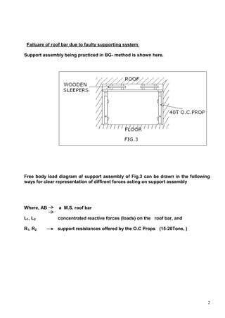
Moment of inertia(I) of I – section beam:
First, we will calculate moment of inertia of rectangular section beam of same dimension.
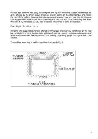
Moment of inertia of rectangular section = b*d3
/12
Where, b= width of section of the rectangular beam,
d = height of section of beam.
t1 = thickness of flange of I- section beam,
t2 = thickness of web of beam.
N1-N2 = neutral line
Now cutting the dotted portion of the rectangular section, as shown in the above figure for
calculating moment of inertia (I) of I- section beam.
Hence, section of cut portion of the rectangular beam will be;
So, M.I. of two cut portions about N1- N2 = 2* (b- t2/2)(d-2t1)3
/12
= (b-t2)(d- 2t1)3
/12
Thus, M. I. of I – section beam (girder) will be;
I = M.I. of rectangular beam – M.I. of cut portions.
Or, I = b*d3
/12 – (b- t2)(d-2t1)3
/12
Or, I = [ b*d3
– ( b- t2)(d-2t1)3
]/12
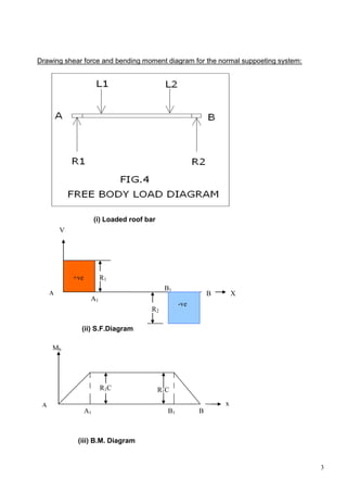
Moment of resistance( bending moment ) can be taken from bending moment
diagram(B.M.D.), as drawn in previous page.
d
b
t2
t1
N2
N1
d - 2t1
b-t2/2
N1
N2
7. 7
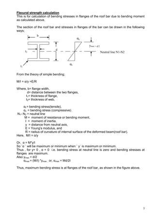
So, maximum bending moment is at centre of the beam(or roof bar );
Or, M = R*C
Where, M = bending moment
R = support resistance by O.C. props, and
C = mid- distance of cogs from the edge of roof bar.
Thickness of web (t2) : 7mm
Cross- section of the web[(d-2t1)*t2)] : 180mm*7mm
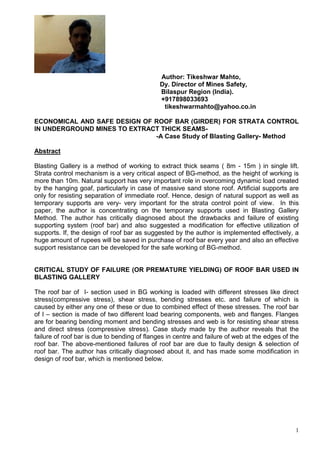
MODIFICATION IN SUPPORTING SYSTEM SUGGESTED BY THE AUTHOR:
The author has done nothing extra, but has made some changes after deep study in BG
method of working. In the changed system of supporting, the wooden lagging are exactly
above the O.C. Props to make direct contact of the O.C. props with the roof of the galleries.
The support capacity or strength of the O.C. props are directly transferred to the roof of the
galleries and not to the roof bar, which eliminates the chances of bending of roof bar and the
O.C. props remain always tightened against the roof. Also, support resistance increases,
which can improve strata condition.
The modified system of support assembly is shown in Fig.6, given below. The support
resistance can further be increased by strengthening roof bars properly at both ends.
Modified supporting system
8. 8
Free body load diagram of the modified system of supporting is shown below in Fig.7
Where,
AB is roof bar
R1 & R2 are support resistances offered by OC props
L1 & L2 are reactive support resistances transferred to the
roof rock, and
L3 , L4 & L5 are concentrated reactive support resistances offered
by roof bar to the roof rock
L1
L3 L4 L5
L2
BA
Fig. 7
R2
R1
9. 9
Drawing shear force and bending moment diagram for modified supporting system:
FREE BODY LOAD DIAGRAM
(i) Loaded beam
(ii) S.F.Diagram
(iii) B.M.Diagram
L1
L3 L4 L5
L2
BA
X
V
A
BA3
A2
A1
+ve
-ve
R1-L1
R2-L2
X
Mb
A
BA1 A2 A3
W (R1-L1)/2 - L3*C
10. 10
Failure of roof bar due to faulty design of roof bar:
The author has studied about the failure of roof bar in the BG- panel, which is only due to
faulty design of roof bar. Roof bar used in early years was of 150mm * 150mm section.
Currently BG- panel is using 200mm*200mm girder of I – section. The thickness of web is
about 7mm. It has become use and throw i.e. after using once; it is being thrown in scrap,
because after failure of web there is no further use in supporting. It has been observed that,
using such type of roof bar is not only wastage of money, but also creating unsafe conditions
and increasing heap of scrap in the mine.
Mode of failure of roof bar observed by the author:
The I-section roof bar( 200mm* 200mm), which is failing in its web due to faulty design of
roof bar and also due to improper strengthening at its ends. The web failure observed by the
author is shown in figure given below.
Section of the failed roof bar (web failure )
11. 11
MODIFICATION IN DESIGN OF ROOF BAR SUGGESTED BY THE AUTHOR
Design of web of roof bar:
Design of web is very important for resisting shear stress and compressive stress. When
roof bar is tightened against the roof, the web is under compression. Therefore, the strength
of web should be such that, it can bear a load upto designed capacity of the O.C. props
(about 30t).
For the designing of web, two things are important. One is web thickness (t2) and another is
its height (h).
So, if we increase the web thickness (t2), the strength of web will increase and, if we
increase the height of web (h), the strength of web will decrease.
Section of web of the roof bar
The strength of web can be expressed mathematically in the following ways;
S α t2, and
S α 1/hn
,so combining these two equations we get;
S α t2/hn
where `α` is proportionality constant.
Or, S =K*t2/hn
where
S = strength of web,
K = proportionality constant,
t2 = web thickness, and
h = height of web.
P = Load on web (value of P
Varies in between 10t and 30t)
n= exponent to `h`
t2
h
P (Load on Web)
P
t2h
12. 12
Here, S should be greater than P, and for this the web shall be strengthened as shown in
figure below.
The author hase observed that the value of web thickness (t2 ) should not be less than
10mm and distance between two flanges (d) not more than 150mm.
Therefore, minimum thickness of web (t2) = 10mm, and
Maximum height of web (h) = d – 2*t1
= (150- 2*10) mm
= 130mm
Design of flanges of roof bar:
As the author has compared the loading parameters of old roof bars and new roof bar, the
bending stresses are less in new type of the bar, which is because of its larger width of
flange.
Design of flange of roof bar includes the design of flange thickness (t1) and width of
flange (b).
Hence, minimum thickness of flange (t1) = 10mm , and
Minimum width of flange (b) = 200mm.
Final design sample of roof bar:
The author has done only thing in modified design, that the web thickness (t2) has been
increased from 7mm to 10mm and distance between two flanges has been decreased from
200mm to 150mm.
Proper Strengthening of Roof Bar:
Strengthening of roof bar is very important and essential for the strata control point of view.
Strata load is transferred vertically on the O.C. props through the roof bar at both ends.
Capacity of the O.C. prop is 40tons; therefore roof bar should be capable to bear the load
coming on the O.C. props. For this the roof bar is to be strengthened properly, otherwise the
roof bar will yield prematurely at the ends and the support assembly will be ineffective.
Thickness of
flange (t1)
b
150mm
200m
m
10mm
10 mm
13. 13
The scheme of proper strengthening of roof bar is shown in the figure given below:
Section of Roof Bar Longitudinal view of the Roof Bar
Section of the strengthened roof bar longitudinal view of the
Strengthened roof bar :
Flange of the bar Web of the girder Edge of the web strengthened
with pieces of C- channel
(2``× 4`` or 3``× 6``)
Plan view of the longitudinal section of the strengthened roof bar
14. 14
COMPAISION OF DESIGN PARAMETERS OF DIFFERENT TYPES OF ROOF BARS
Design
Parameters
Old type of Roof Bars
150mm*150mm 150mm*200mm
Currently using
Roof Bar
200mm*200mm
Modified Roof
Bar
200mm*150mm
Web thickness
(t2)
9 – 10mm 7mm 7mm 10mm
Thickness of
Flange (t1)
10.5mm 10.5mm 10mm 10mm
Width of
Flange (b)
150mm 150mm 200mm 200mm
Distance between
Flanges (d)
150mm 200mm 200mm 150mm
Moment of
Inertia(I) of Roof
Bar
1714.28cm4
3050.2cm4
3953.53cm4
2146.42cm4
Cross- section of
Roof Bar
4525mm2
4403mm2
5260mm2
5300mm2
Cross- section of
Web
1240mm2
1218mm2
1260mm2
1300mm2
15. 15
Advantages of the modified supporting system and modified design of roof bar:
It eliminates the bending of roof bar, which can be re –utilized ;
Strengthened roof bar can bear a minimum of 30t (compressive) load;
fully utilization of strength of OC props, because props are tightened against the roof and not
to the roof bar ;
support resistance offered by OC props are improved tremendously after modification in
supporting system and design of roof bar. Hence less chances of bed separation ;
rock load will be resisted by the OC props and not by the roof bar, hence abutment pressure
at side will be less which will minimize side spalling ;
props will be tightly intact with roof, therefore no chances of props dislodgment by hitting
side spalled boulders ;
overriding of pillars and stooks will be reduced ;
It will provide safe working conditions for men, machinery and property.
It will be very- very economical and purposeful;
Saving of wastage of money in purchasing roof bar every year.
Conclusion:
The author has given valuable suggestion regarding supporting system in BG working After
applying the author’s suggestion, support resistance has improved in BG working. The
improvement in support resistance has decreased the chances of layer separation and over
riding of pillars. It is very economical and purposeful. It can save about Rs. 50 Lacs per
annum on purchase of roof bar.
Declaration:
The above observations and comments are of author and not necessarily to the
organization.
Signature of author
(Tikeshwar Mahto )
Date- 11. 8.15 Dy. Director of Mines Safety,
Bilaspur Region (India)
+917898033693
tikeshwarmahto@yahoo.co.in