Downloaded 491 times

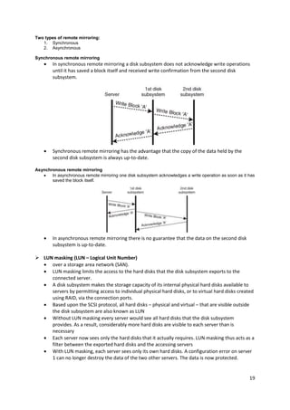

The document discusses intelligent disk subsystems and their caching mechanisms to enhance hard disk access speeds, explaining both write and read caches utilized in disk controllers and RAID systems. It also covers advanced features like instant copies, remote mirroring, and LUN masking, emphasizing their importance in data protection and efficient storage management. Furthermore, it outlines the physical I/O path from CPUs to storage systems, comparing technologies like SCSI and Fibre Channel, and introduces IP storage as a cost-effective alternative for building Storage Area Networks (SANs).


![System simulation & modeling notes[sjbit]](https://cdn.slidesharecdn.com/ss_thumbnails/systemsimulationmodelingnotessjbit-110929031610-phpapp01-thumbnail.jpg?width=640&height=640&fit=bounds)