Downloaded 65 times
![THE JOURNAL TJ
22 SÉBASTIEN JOBERT, KENNETH HANN
Volume 10 | Part 1 - 2016
SYNCHRONISATION AND
TIME DISTRIBUTION
IN MODERN TELECOMMUNICATIONS NETWORKS
SÉBASTIEN
JOBERT,
KENNETH
HANN
The changing
picture
The past decade has witnessed a
race for networks to provide ever
faster communications,
interconnecting people via
applications used every day by
billions of users. Radio spectrum
utilisation and synchronisation
plays a key role here.But now
that Ethernet has won the
bandwidth and cost per bit wars,
how are base stations being
synchronised today?
For many years,synchronisation was a by-
product of the transmission network,but
technology changes in both mobile and fixed
networks has transformed synchronisation
into an essential service.Requirements are
becoming more demanding and the
traditional means of delivering network
synchronisation are evolving.
Time synchronisation enables mobile
techniques such asTime Division Duplex,
Coordinated Multipoint transmission and
reception,and Multicast-Broadcast Single-
Frequency Network.When mobile networks
are precisely synchronised as shown in
Figure 1,performance and throughput can be
increased.
There is a paradox here:while mobile
networks have an increased requirement for
synchronisation,transport networks,that
were once synchronous and therefore
capable of carrying frequency
synchronisation at the physical layer,have
largely lost that capability.So now thatTime
Division Multiplexing (TDM) networks are
replaced by modern,packet-based,
communications networks,how can such a
synchronisation service be arranged?
In addition to mobile networks,accurate
synchronisation is a potential enabler for new
paradigms,such as the Internet ofThings
(IoT) and virtualisation techniques.This
provided motivation to develop new
synchronisation technologies for transport
networks.
Two main candidates were in the starting
blocks ten years ago:
• Synchronous Ethernet [1] A physical layer
technology that inherited the pedigree of
the Synchronous Digital Hierarchy (SDH).
Central
Office
Mobile Backhaul
Network
Common time reference
carried over the network
µs accuracy
µs accuracy
Neighboring cells
need us accuracy
Figure 1:Time synchronisation is essential to some mobile communications technologies.](https://image.slidesharecdn.com/thejournalvol10part122-29-180411075015/75/Synchronisation-and-Time-Distribution-in-Modern-Telecommunications-Networks-1-2048.jpg)
![23
INFORM NETWORK DEVELOP
• IEEE 1588TM
[2] A packet-based protocol
technology using timestamps,a rookie in
telecommunications networks,but a touted
successor to NetworkTime Protocol.
Synchronous Ethernet
WhileTDM networks required a steady rate to
avoid slips (corresponding to a buffer that
empties or overflows),packet networks such
as Ethernet have been designed to work
asynchronously,saving on oscillator cost,and
removing the need for clock selection and
holdover.
Although cost reduction was an important
factor for network operators,the use of
Ethernet broke the timing distribution to the
mobile networks [3].The solution was simple
– make Ethernet synchronous:the so-called
SyncE (Synchronous Ethernet) technology
was born! Carrier Ethernet does not require
synchronisation as such; the key driver for
synchronisation on such networks is only to
carry timing up to mobile cell sites.SyncE
offers continuity in the synchronisation
distribution chain across routers and
switches and operators like to use it
wherever possible.
The standardisation of SyncE was supported
by European operators who saw this
technology as a way to migrate their
networks towards Ethernet while maintaining
a link-by-link timing hierarchy fully
compatible with SDH (see Figure 2).
SyncE ensures that the data bits transmitted
at the physical layer are in step with a
reference rhythm usually derived from a
Primary Reference Clock (PRC).SyncE is
therefore a frequency synchronisation solution
(although there has been a proposal to expand
this to carry also phase/time [4]). Figure 3
illustrates the distinction between frequency
THE JOURNAL TJ
SYNCHRONISATION AND TIME DISTRIBUTION IN MODERN TELECOMMUNICATIONS NETWORKS
In addition to mobile
networks, accurate
synchronisation is a
potential enabler for new
paradigms, such as the
Internet of Things (IoT)
and virtualisation
techniques.
“
”](https://image.slidesharecdn.com/thejournalvol10part122-29-180411075015/75/Synchronisation-and-Time-Distribution-in-Modern-Telecommunications-Networks-2-2048.jpg)
![THE JOURNAL TJ
24 SÉBASTIEN JOBERT, KENNETH HANN
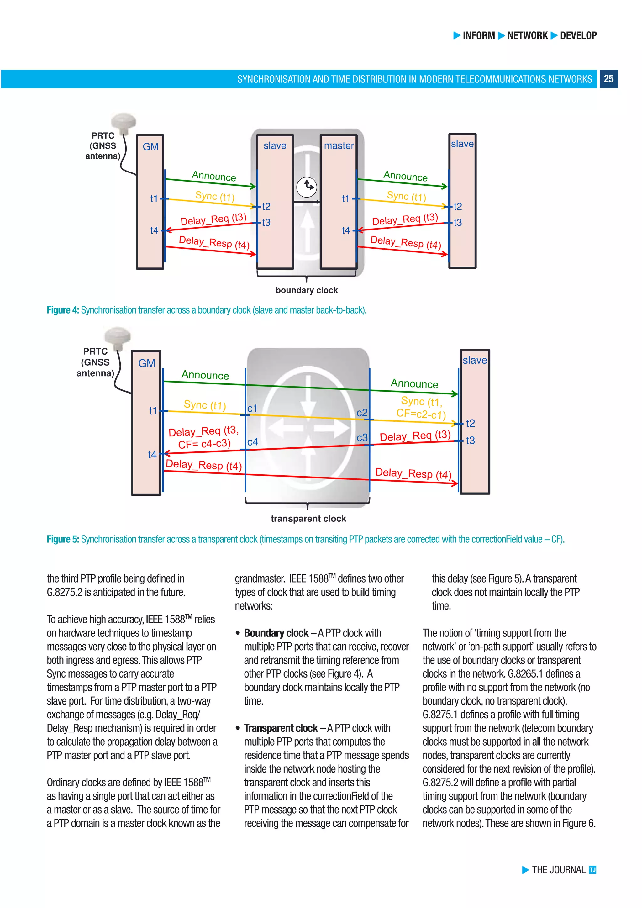
and phase/time synchronisation. The
Synchronisation Status Message that used to
be carried as 4 bits in the SDH overhead,can
be found in the bowels of SyncE carried via a
slow protocol,called Ethernet Synchronisation
Messaging Channel.Synchronisation Status
Messages indicate when there is a failure in
the distribution chain and that the received
physical layer signal is no longer traceable to a
PRC.
Note that,while SyncE does not carry
phase/time synchronisation,it is considered a
useful technique in combination with IEEE
1588TM
in order to maintain phase/time
holdover in case of failure.An example of this
is where time is set via the PrecisionTime
Protocol (PTP) (discussed below),but upon
losing the PTP connection,time is advanced
using ticks from SyncE.Some industries even
combine these two standards to achieve
incredibly high time accuracy [5].
SyncE is widely implemented in Ethernet
telecoms devices and used in many
networks,especially for mobile backhaul.
The standards defining SyncE are stable; one
new performance enhancement to SyncE
clocks is currently being defined in ITU-T to
reflect the fact that SyncE implementations
typically exceed the previous generation of
ITU-T requirements by at least one order of
magnitude.In the race for mobile,SyncE was
first out of the blocks.
IEEE 1588TM
– PTP and telecoms profiles
An alternative to SyncE for delivering both
frequency and phase/time synchronisation
is known as IEEE 1588TM
which defines PTP.
IEEE 1588TM
started out as a mechanism for
forming a synchronisation hierarchy across
an Ethernet network and was developed for
applications ranging from instrumentation
and measurement to power and
automation.Telecoms was not originally
represented. IEEE 1588TM
was first
published in 2002 with a second version
ratified in 2008 [2] that includes options for
telecoms and a mechanism of making
specific industry profiles (telecoms profiles
are based on this version).A third version is
currently under definition.
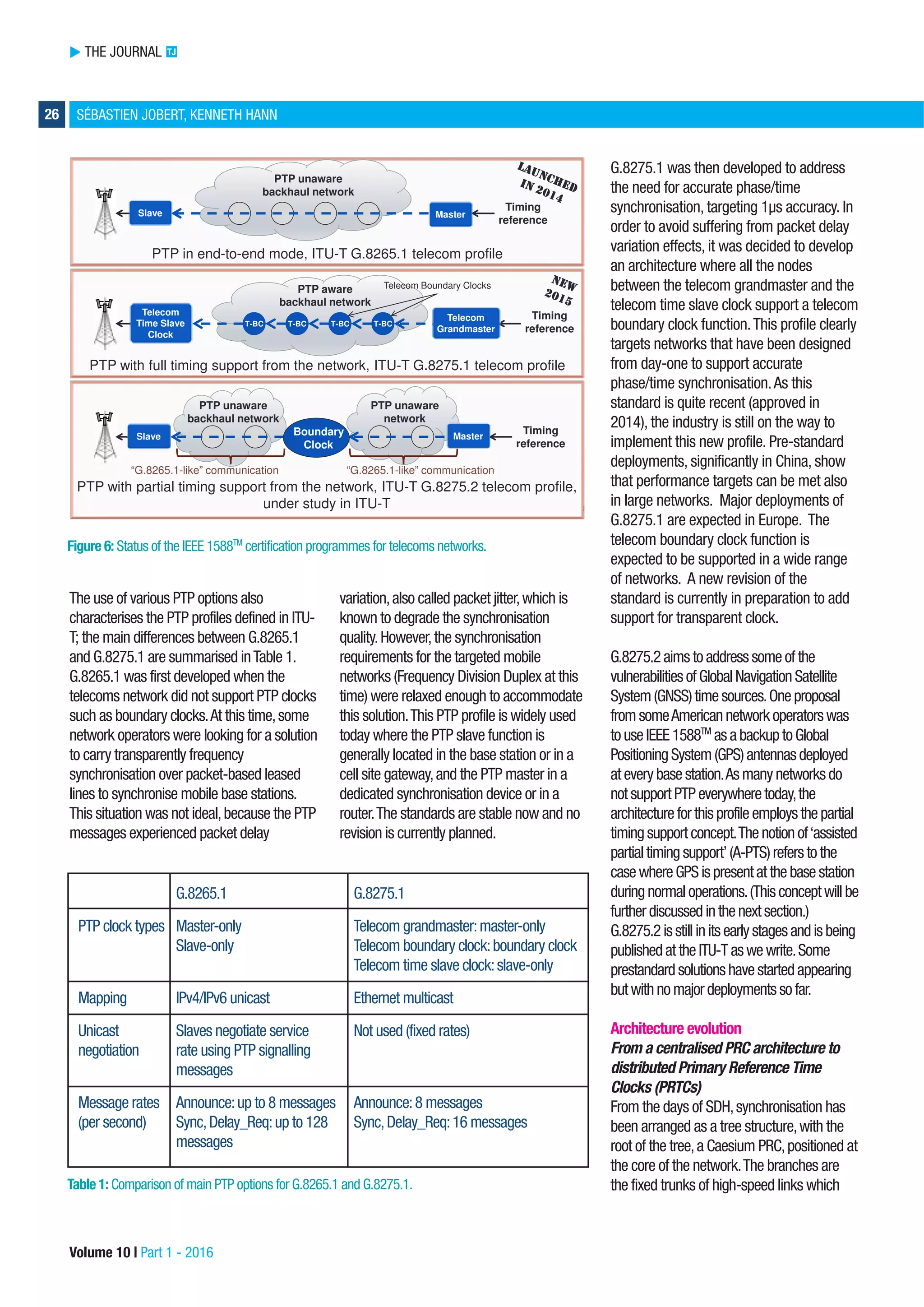
ITU-T decided to define a PTP profile for
frequency distribution in Recommendation
G.8265.1 [6].Later,a second PTP profile was
defined for phase/time synchronisation in
G.8275.1.A third profile is now under
definition in the emerging Recommendation
G.8275.2.
In order to verify that the PTP options are
correctly implemented according to these
profiles,the IEEE recently launched a
certification programme; the first certification
programme in the IEEE’s history [7] and it
aims to help network operators deploy
compliant PTP products.The PTP telecom
profiles G.8265.1 and G.8275.1 are currently
available in the certification programme,and
Volume 10 | Part 1 - 2016
Figure 2: Synchronous Ethernet is a link-by-link solution,all switch and router devices must implement a SyncE clock.
Figure 3: Difference between frequency and phase/time synchronisation.
Switch/RouterSwitch/Router
SyncE aware backhaul network PRC-traceable
frequency reference
SyncE clock
Switch/Router
SyncE clock SyncE clock
ESMC
frames
SyncE signal
Switch/Router
SyncE clock
ESMC: Ethernet Synchronisation Messaging Channel](https://image.slidesharecdn.com/thejournalvol10part122-29-180411075015/75/Synchronisation-and-Time-Distribution-in-Modern-Telecommunications-Networks-3-2048.jpg)

The document discusses the evolution of synchronization technologies in telecommunications, emphasizing the importance of accurate time distribution for mobile networks, the Internet of Things (IoT), and virtualization. It covers the development of Synchronous Ethernet and IEEE 1588 (Precision Time Protocol), detailing their roles in achieving frequency and phase/time synchronization across networks. The document also highlights the challenges and solutions related to implementing partial timing support in legacy networks, aiming to enhance synchronization reliability and performance.