1. IEEE 1588 - Precise Time Synchronization as the Basis for Real Time
Applications in Automation
More and more data can be transferred and processed in shorter and shorter time. This trend is
observed in automation technology. Because of this, Ethernet has been chosen as the transport
technology for the foreseeable future.
Beside speed of transmission and ease of setup, the words “real time” have a special meaning in
this field. A substantial facet is precise time synchronization of different end devices.
With the Precision Time Protocol IEEE 1588 there is now, for the first time, a standard available
which makes it possible to synchronize the clocks of different end devices over a network at speeds
faster than one microsecond.
This article is written to supply answers to several questions: how this protocol works, how to use
and implement it, and what results you can expect.
Real-time
If hard real-time requirements are to be met, then the communication system must be able to guarantee
deterministic behavior. This means always being able to exchange the required amount of data within a
predefined time and the ability to provide mechanisms to synchronize all participants very precisely.
Today only a few special field buses or other proprietary solutions are suitable for achieving cycle times of
less than one millisecond or jitter values in the range of a microsecond. To be able to continue the trend
towards using Ethernet for networking in automation systems, special measures were created whereby
Ethernet can guarantee the required determinism.
There is a degree of variance in Ethernet propagation times during transmission. A solution to guarantee
deterministic system behavior is to have a precise clock in all terminal devices synchronized with all other
systems. If actions are referred to such a high precision clock, then the process can be decoupled from the
propagation times of the communication.
This issue applies particularly to co-operating systems that must start specific actions simultaneously. An
example is several robots that work together on one task, e.g. the transport of heavy objects, something that
can only function if the movements of the robots are very precisely matched to each other.
IEEE1588
The new IEEE Standard Precision Time Protocol (PTP) IEEE1588 is now a very comprehensive solution to
do very precise time synchronization in an Ethernet network.
The protocol was originally developed by Agilent for distributed instrumentation and control tasks. The
technique is based on the work of John Eidson, who, as chairman of the standardization committee, is
largely responsible for the approval of the standard in November 2002.
Using IEEE1588, it is possible for the first time to synchronize, in the sub-microsecond range, the local
clocks in sensors, actuators, and other terminal devices using the same Ethernet network that also
transports the process data.
Without such a standardized synchronization protocol, which is defined to be used with any protocol, not just
Ethernet, it would probably not be possible to synchronize local clocks in terminal devices from different
manufacturers with this precision.
Existing time synchronization protocols such as NTP and SNTP do not achieve the required synchronization
accuracy or the convergence speed. Others, such as SynUTC from the Technical University in Vienna, were
not accepted on the market.
2. Like other protocols, PTP is based on the most precise matching of times when synchronization packets are
transmitted and received possible. Unlike SNTP, the transmission time stamp does not need to be
transmitted in the synchronization packet itself, as described in detail below, but is transmitted in a following
packet. In this way measurement of transmission and reception, and transmission of measured time stamps
can be decoupled.
The protocol was designed for small homogeneous and heterogeneous local networks. The designers paid
particular attention to low resource usage so that the protocol can also be used in low end and low cost
terminal devices. No special requirements are placed on memory or CPU performance, and only minimal
network bandwidth is needed. The low administration effort for this protocol is also significant. As redundant
masters are also supported, a PTP domain automatically configures itself using the best master clock
algorithm and is also fault-tolerant,.
The most important characteristic of the protocol is the synchronism in the microsecond and sub-
microsecond range.
Many groups are interested in IEEE 1588
The biggest interest in determinist Ethernet currently is found in automation; especially motion control
applications. Many drive manufactures are equipping their devices with Ethernet interfaces, but now have
problems synchronizing all connected drives as precisely as possible over the network.
Several groups of this industrial sector have decided to use this protocol in their Ethernet based field busses.
The ODVA has decided to use IEEE1588 for CIPSync, the real-time extension for Ethernet/IP - CIP.
Siemens is working on a modification of IEEE1588 for Profinet V3. Also solutions by Beckhoff and Jetter are
being developed to ensure time synchronization with this protocol or a similar approach. Likewise the EPSG
(Ethernet Powerlink Standardization Group) has planned this protocol as a firm component of the version 3
of their specification.
But interest is not only coming from the automation industry. Increasing demand is growing out of test and
measurement; the origin of this protocol. Also initial projects have been started to use IEEE1588 for military
applications. Other groups which show interest are coming from telecommunications and electrical power
distribution (IEC61850 -Communication networks and systems in substations).
Before we focus on initial results, a short overview of the function of this protocol is given.
How does the IEEE1588 protocol work
The basic function is that the most precise clock on the network synchronizes all other users. A clock with
only one network port is termed an ordinary clock. There are two clocks, Master and Slave. In principle any
clock can perform both the master and slave function.
The precision of a clock, more exactly stated of their time sources, is categorized by the protocol in classes
(stratum). Here the highest class is an atomic clock which has the stratum value 1. The selection of the best
clock in the network is performed automatically using the best master clock algorithm.
The precision of the synchronization depends very heavily on the network and the components used in the
network. For this reason the transition over less deterministic components, e.g. routers and switches, is also
made possible by the protocol using the boundary clock.
For the administration and configuration of clocks in the network, there is also a management protocol
available.
PTP is based on IP multicast communication and is not restricted to Ethernet, but can be used on any bus
system that supports multicasting. Multicast communication offers the advantage of simplicity; IP address
administration does not need to be implemented on the PTP nodes. Furthermore, PTP can thus be scaled
for a large number of PTP nodes.
3. Time synchronization
Every slave synchronizes to its master's clock by exchanging synchronization messages with the master
clock.
The synchronization process is divided into two phases. First the time difference between master and slave
is corrected; this is the offset measurement.
Follow Up
Offset = TS1 - TM1 - Delay
= 1002 - 1051 - 0 = - 49
Adjust Time: Ts - Offset = Ts - (- 49)
Ts = 1001
Ts = 1000sTm = 1050s
TM1 = 1051
TS1 = 1002
Master Slave
Line Delay = 1s
TM1
not known yet
Follow Up
Adjust Time: Ts - Offset = Ts - 0
Ts = 1052TM2 = 1053
TS2 = 1053TM2
Offset = TS2 - TM2 - Delay
= 1053 - 1053 - 0 = 0
Sync
Sync
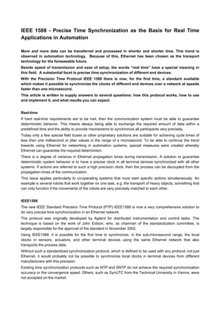
Figure 1 Offset correction
During this offset correction, the master cyclically transmits a unique synchronization (SYNC) message to the
related slave clocks at defined intervals (by default every 2 seconds). This sync message contains an
estimated value for the exact time the message was transmitted.
For highly accurate synchronization a mechanism is now provided that determines the time of transmission
and reception of PTP messages as precisely and as closely as possible to the hardware, best of all directly
on the medium.
The master clock measures the exact time of transmission TM1 and the slave clocks measure the exact
times of reception TS1. The master then sends in a second message, the follow-up message, the exact time
of transmission TM1 of the corresponding sync message to the slave clocks.
On reception of the sync message and, for increased accuracy, on reception of the corresponding follow-up
message, the slave clock calculates the correction (offset) in relation to the master clock taking into account
the reception time stamp of the sync message. The slave clock Ts must then be corrected by this offset. If
there were to be no delay over the transmission path, both clocks would now be synchronous.
The second phase of the synchronization process, the delay measurement, determines the delay or latency
between slave and master. For this purpose the slave clock sends a so-called "delay request" packet to the
master and during this process determines the exact time of transmission of the message TS3. The master
generates a time stamp on reception of the packet and sends the time of reception TM3 back to the slave in
a "delay response" packet.
4. Follow Up
Offset = TS4 - TM4 - Delay
= 1083 - 1083 - 1 = -1
Adjust Time: Ts - Offset = Ts - (- 1)
Ts = 1082
Ts = 1069sTm = 1070s
TM4 = 1083
TS4 = 1083
Master Slave
Line Delay = 1s
TM4
Delay Response
Delay Request
Delay = (TS2- TM2) + (TM3 - TS3) / 2
= 0 + (1082 - 1080 ) / 2 = 1
TS3 = 1080Tm = 1081
TM3 = 1082
synchronous !
TM3
Follow Up
Offset = TS5 - TM5 - Delay
= 1086 - 1085 - 1 = 0
Ts = 1085TM5 = 1085
TS5 = 1086TM5
now knownSync
Sync
Figure 2 Delay measurement
From the local time stamp for transmission TS3 and the time stamp for reception provided by the master
TM3, the slave calculates the delay time between slave and master.
The delay measurement is performed irregularly and at larger time intervals (random value between 4 and
60 seconds by default) than the offset measurement. In this way, the network, and particularly the terminal
devices, are not too heavily loaded. However, a symmetrical delay between master and slave is crucial for
the delay measurement and its precision, i.e. same value for both directions.
Using this synchronization process, timing fluctuations in the PTP elements especially the protocol stack and
the latency time between the master and slave are eliminated.
PTP reference architecture, or how to build a PTP synchronization element
As previously mentioned, what is so special about the architecture is the separation of the time-critical part
which is implemented in hardware and the protocol itself and is decoupled from hard real-time conditions -
the software part. Thus the protocol is running in a low priority process and/or on a processor with low
performance requirements.
The hardware unit consists of a highly precise real-time clock and a time stamp unit (TSU) to generate the
time stamp. The software part implements the actual IEEE1588 protocol with the binding to the real-time
clock and the HW time stamp unit. Figure 3 illustrates a co-operating of the hard and software component of
a IEEE1588 synchronization element.
5. T X
R X
H W
R e a ltim e
C lo ck
T S U
T S U - T im e S ta m p U n it
P H Y
S y n c & D e la y _ R e q
se n d in g a n d re c e ip t tim e
(x )M II
S y n c h ro n iza tio n E le m e n t
S e t/G e t
tim e
I E E E 1 5 8 8
P re c isio n T im e P ro to c o l
T im e S ta m p
In terfa c e
C lo c k
In te rfa c e
P o rt
In te rfa c e
M A C
N e tw o r k
P ro to c o l
sta c k
H W
S W
Figure 3: Synchronization Element
The intention of the presented architecture supports an almost OS independent modeling of the software
component.
In order to reach this, we introduced three layers with different abstraction level. The Protocol Layer
implements the operating system independent Precision Time Protocol. The OS Abstraction Layer forms
the interface between PTP and the selected operating system. The functions made available by the
operating system - tasks/processes, semaphores, timers, sockets, etc. - are merged over the OS Layer. The
following figure shows the interaction of the individual layers.
Protocol Layer,
OS independent
OS Layer
IEEE1588
Precision Time Protocol
call
Dispatcher
protocol
input
PTP
Clock
Interface
PTP
Timestamp
Interface
PTP
Port
Interface
Queue
PTP API
OS abstraction Layer
timer RX/TX
PTP messages
Sync and Delay Request
time stamp
set and read
time
Synchronisation
PTP Management
Dispatcher
Best Master Clock
Algorithm
push
pop
Figure 4: interaction diagram
The highest layer implements PTP for the synchronization of clocks in a network and can be used on
different communication elements (PC, switch, router, etc..). Here is the actual intelligence located for
synchronizing the individual communication elements. Within the Protocol Layer we used only ANSI/ISO C
conformal functions, thus you can easily transfer the protocol without deep interference into the functionality
on different platforms. The protocol dispatchers ensures the atomic execution of functions during an
individual process. Communication between the protocol and the OS Abstraction Layer has been realized by
a queue and three well defined interfaces.
The middle layer encases operating system dependent functions, which one must adapt, if necessary.
The Timestamp Interface provides the Precision Time Protocol with the seized time stamps of the Sync and
Delay-Request messages. However depending upon the stage of development (precision requirement)
6. either a HW unit (TSU) or the software generates the time stamps. The best way to generate "software time
stamps” is in the operating system dependent NIC drivers (RX- ISR, sends process) - as near as possible at
the transportation medium.
Over the Clock Interface you read and modify the local clock. You have also to adapt these functions
depending upon platform. Realizations, which do not have a hard real-time clock, use the system clock of the
operating system or optimized solutions as for example the nano-kernel under UNIX derivatives. Apart from
setting the local clock, this interface contains the control algorithms which are responsible for the quality of
time synchronization [accuracy, stability, transient behavior, etc.].
The Port Interface is used to dispatch and/or receive PTP messages. The IEEE1588 telegrams use
excluding UDP/IP multicast packets and thus make it possible to send and receive them over the
socket interface of the IP protocol stack. One may neglect temporal requirements, since the time stamps are
generated directly at transport medium. The inputs to the protocol (configuration, diagnosis, PTP packets)
run over the PTP API.
This modular software platform made it possible for us to build implementations of this protocol for Linux,
Windows and VxWorks. The implementations in Windows and Linux use time stamping in software. But even
a pure software implementation reaches a precision of about 100 µs, and it seems to be possible to increase
this up to a precision of better than 10 µs.
IEEE1588 and Switches
The precision of the protocol also depends on the latency jitter of the underlying network topology. Point to
point connections provide the highest precision, with hubs imposing very little network jitter. Under very low
or no network load, Layer 2 switches have a very low processing time, typically 2 to 10µs plus packet
reception time. In this case, new switch designs also have low latency jitter e.g. the Hirschmann Switch
RS2-FX/FX with about 0.4 µs latency jitter.
But switches are working with queues and store and forward, so only one queued maximum length packet
imposes a delay for the following packet of about 122µs, and under high load conditions, more than one
packet will be in the queue. The next issue for the precision of the protocol is that latency is completely
symmetric for both directions: from the master to the slave and visa verse. This can nearly never be
guaranteed under higher network loads.
Prioritization of packets e.g. IEEE802.2D/p does not really solve the problem, because at least one long
packet can be in front of a synchronization packet and so will impose up to 122µs to the jitter of transmission.
Currently, available switches show that after the priority scheduler, there is another queue for 2 up to 8
packets, and not only one as expected. This means a jitter from 360µs up to 1ms under heavy load
conditions.
The solution for all these problems is the usage of IEEE 1588 Boundary clocks in switches. In this case you
only have point to point connections and there is nearly no delay jitter between master clock and slave clock
and internal queuing delay/jitter of switches is not relevant any more.
7. M
= SLAVE CLOCK
= MASTER CLOCK
SM M
S
S
S
M
M
S
MASTER CLOCK BOUNDARY CLOCK SLAVE CLOCKS
„1588 Switch“
Figure 5: network with boundary clock
Test results
In the beginning, we directly connected in our test setup two Ordinary Clocks. We used IEEE1588 enhanced
plug-in modules on our modular Ethernet switches (MICE series). To put the protocol through its paces, we
added a high network load with an Ethernet packet generator.
So that we could examine the difference between local clock and reference clock as close-to-applications as
possible, we enhanced both units with a Pulses Per Second (PPS) signal output and connected them to an
oscilloscope. Thus we could seize now very elegantly the deviation of the two signals and also represent the
frequency distribution of the deviation. The synchronization accuracy which we reached lay within ± 100 ns
(max. jitter). The measurement ran for a period of 84 hours.
PPS Out
Fast Ethernet
PPS Out
Grandmaster Slave
synchronizes
Figure 6: test setup
The following figure shows the frequency distribution of the offset values between master clock and slave
clock in nanoseconds. The standard deviation amounts to 23.95 ns and the average value -4.248 ns.