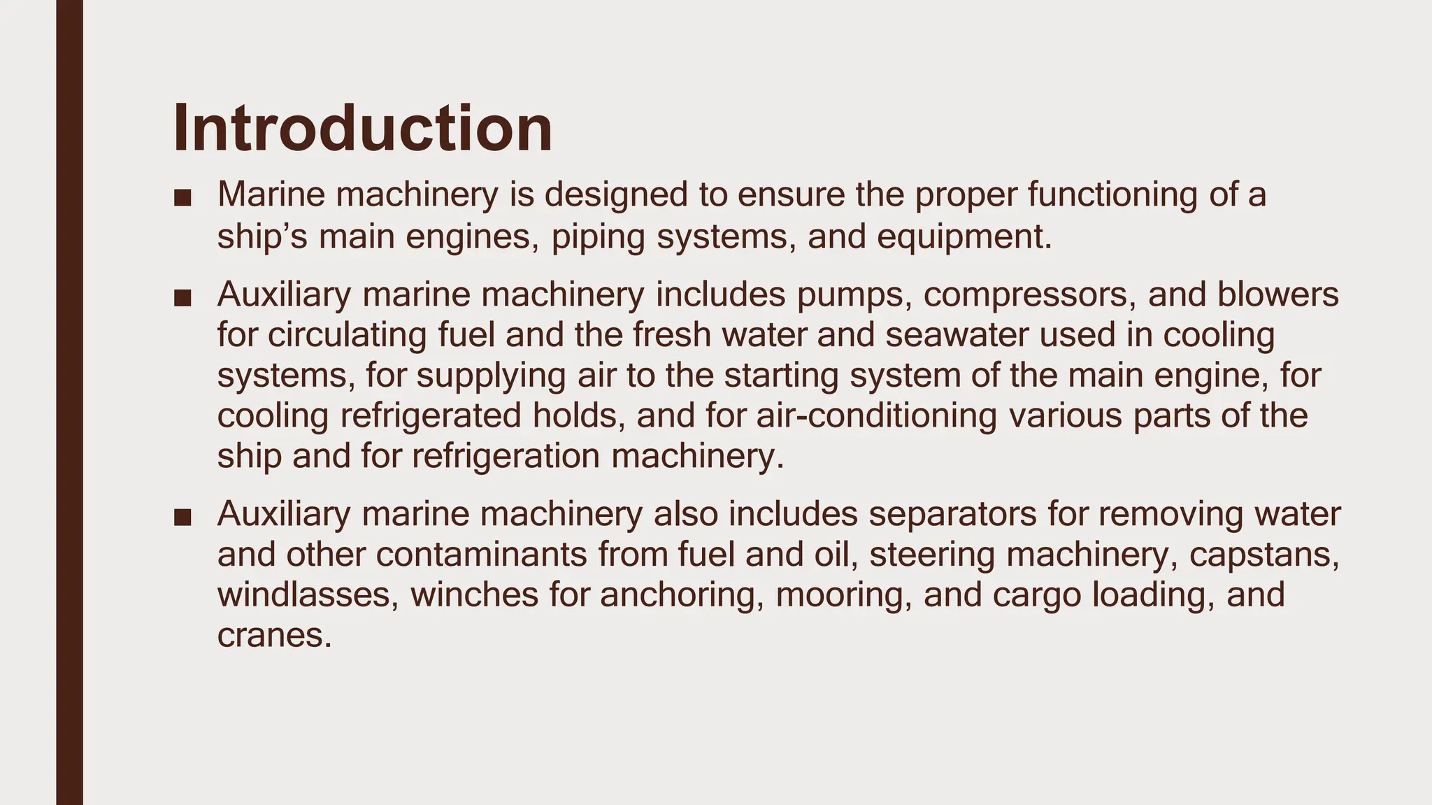
The document discusses auxiliary marine machinery systems essential for the proper functioning of ships, including pumps, compressors, and steering machinery. It emphasizes the importance of efficient piping systems, their design, and the role of various fittings and symbols in ensuring operational safety. Additionally, it covers pump operation fundamentals, total head losses calculations, and the net positive suction head necessary for effective pump functionality.


![Example (1)
(PB= 1bar), (Lsuc Suction head above pump=23 m), (Vp= 0.17 bar
, at 25 ˚C), (hf =7m) – fresh water liquid
By aid of simple sketch describe above example & Calculate the NPSH and the gauge reading at pump
suction
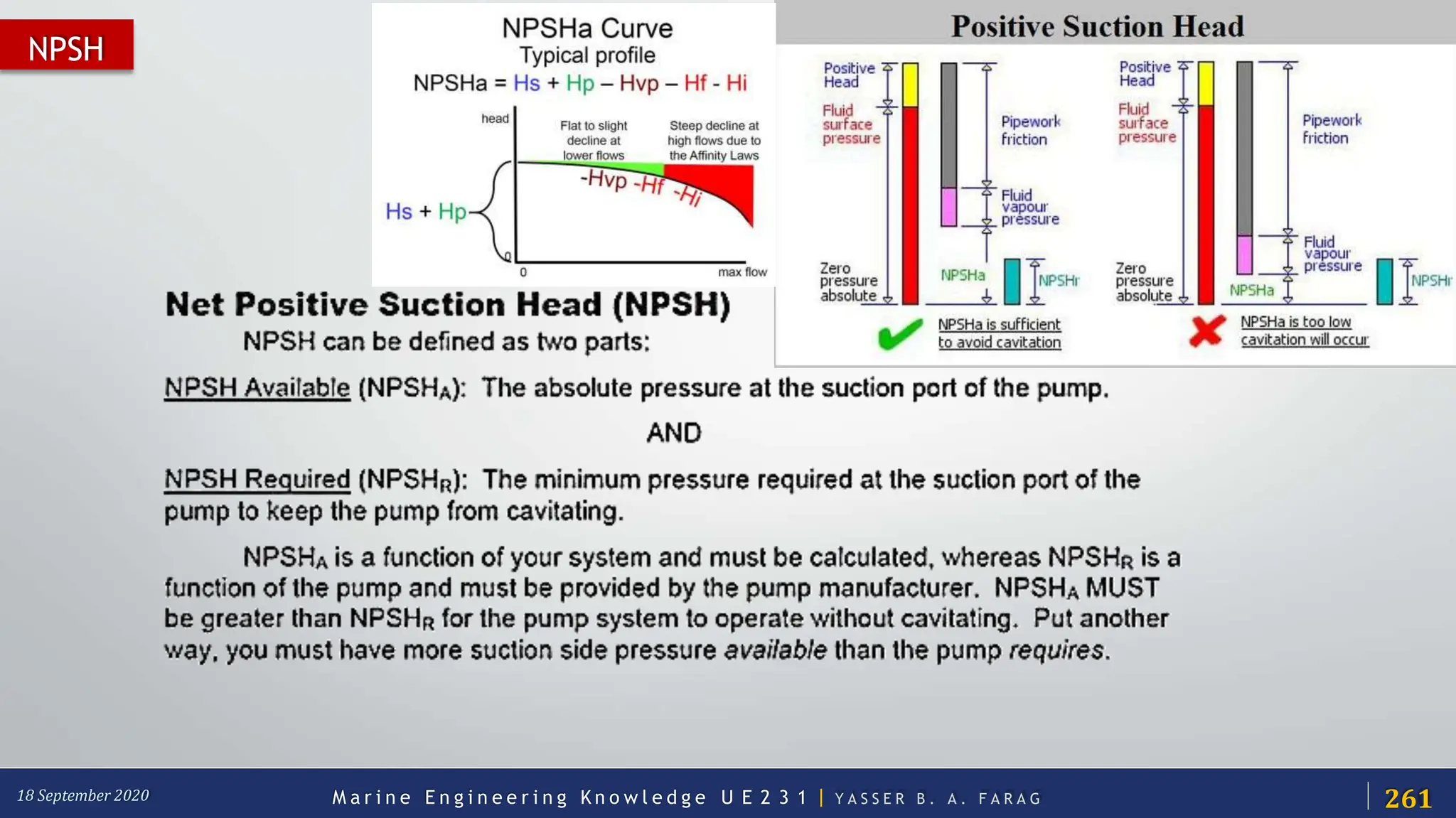
PB : Barometric pressure.
LSuc: Suction head [above pump (+) / under pump (-)].
Vp: V
apor pressure.
hf: Friction losses in the piping system leading to pump suction.
2
4
.3m
263
M a r i n e E n g i n e e r i n g K n o w l e d g e U E 2 3 1 | Y A S S E R B . A . F A R A G
18 September 2020](https://image.slidesharecdn.com/marineauxilarysystem-240422041749-3df65d9d/75/marine-auxilary-complete-vessel-system-pptx-49-2048.jpg)
![(PB= 1bar), (Lsuc Suction head above pump=23 m),
(Vp= 0.75 bar at 90 ˚C), (hf =7m) – fresh water liquid -
By aid of simple sketch describe above example & Calculate the NPSH and the gauge reading at pump
suction
PB : Barometric pressure.
LSuc: Suction head [above pump (+) / under pump (-)].
Vp: Vapor pressure.
hf: Friction losses in the piping system leading to pump suction.
1
8
.6
4m
Example (2)
264
M a r i n e E n g i n e e r i n g K n o w l e d g e U E 2 3 1 | Y A S S E R B . A . F A R A G
18 September 2020](https://image.slidesharecdn.com/marineauxilarysystem-240422041749-3df65d9d/75/marine-auxilary-complete-vessel-system-pptx-50-2048.jpg)


![• Total leakage calculation:
Well maintained system: less than 10%
leakages
Leakage (%) = [(T x 100) / (T + t)]
T = on-load time (minutes)
t = off-load time (minutes)
•
Leak Quantification Method
Assessment of Compressors](https://image.slidesharecdn.com/marineauxilarysystem-240422041749-3df65d9d/75/marine-auxilary-complete-vessel-system-pptx-688-2048.jpg)

![2
• Compressor capacity (m3/minute) = 35
Cut in pressure, kg/cm2 = 6.8
Cut out pressure, kg/cm2 = 7.5
Load kW drawn = 188 kW
Unload kW drawn = 54 kW
Average ‘Load’ time =1.5 min
Average ‘Unload’ time = 10.5 min
•
•
•
•
•
•
Example
Assessment of Compressors
Leakage = [(1.5)/(1.5+10.5)] x 35 = 4.375 m3/minute 1
© UNEP 2006](https://image.slidesharecdn.com/marineauxilarysystem-240422041749-3df65d9d/75/marine-auxilary-complete-vessel-system-pptx-690-2048.jpg)