Download to read offline


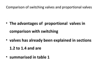
![• HORSE POWER = [FLOW (GPM) x PRESSURE (PSI)]
/ [1714 x efficiency]
• And the power consumed by the electric motor
is:
• HORSE POWER = 1.73 x LINE VOLTAGE x LINE
CURRENT x COS Ø ÷ 746
• Take cos Ø to be 0.8 and pump efficiency at 93%](https://image.slidesharecdn.com/random-160709112115/85/slide-251-320.jpg)


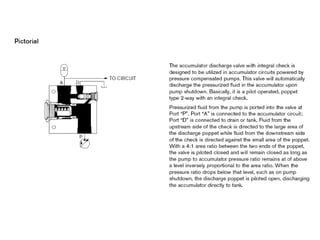


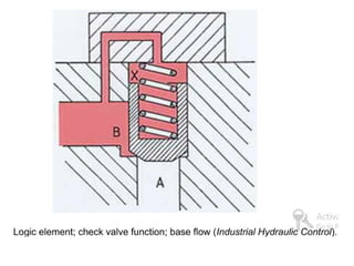


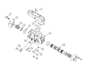


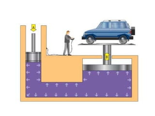
The document provides detailed information on hydraulic systems, focusing on principles such as hydraulic power, types of pumps including positive displacement and dynamic pumps, and key calculations for performance and energy efficiency. It explains concepts like potential and kinetic energy, Pascal's law, and specifics about different pump operations like gear and vane pumps. Additionally, it covers components of hydraulic circuits, including valves, pressure sensors, and system design considerations.