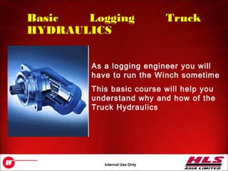
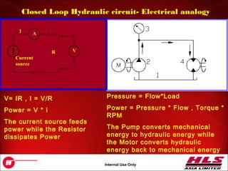
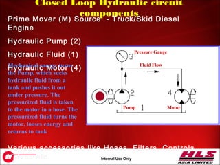
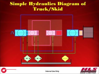
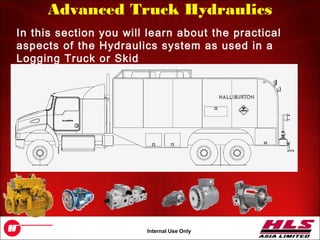
OH043.1
Internal Use Only
Basic Logging Truck
Hydraulics
OH043.2
Internal Use Only
Basic Logging Truck
HYDRAULICS
As a logging engineer you will
have to run the Winch sometime
This basic course will help you
understand why and how of the
Truck Hydraulics
OH043.3
Internal Use Only
Why Hydraulics
• Transmission of power is very easy and flexible
using Hydraulics. Pumps and Motors are connected
by flexible hoses
• It is safe in the sense that it does not have fire or
electrical hazards. Remember we need to switch
OFF / Disconnect the Truck Alternator during
Explosive related operations yet the Winch has to
move. Hydraulics can be run from the Truck 12 V
Battery
• It is relatively maintenance free. Just keep changing
Oil & Filters regularly as scheduled in PM manuals
• Hydraulic operations are smooth and noiseless.
• The ease with which one can control Speed, Torque,
Direction of the winch by operating just one Joy
Stick
OH043.4
Internal Use Only
Hydrostatic laws
• If pressure is applied
on surface of the
same area, the forces
which are produced
are the same size.
• Forces depend on
height of liquid not on
the shape of the
container in which
liquid is placed.
• Hydrostatic laws
assume an ideal fluid
which is
incompressible,
frictionless and
without mass.
OH043.5
Internal Use Only
Pascal’s law
• The effect of a force
acting on a stationery
liquid spreads in all
directions within a
liquid.
• The amount of
pressure in the liquid
is the equal to the
weight force, with
respect to the area
being acted upon.
• The pressure always
acts at right angles to
the limiting surface of
the container.
OH043.6
Internal Use Only
Pressure due to external force
• P = F1/A1
• F2 = P.A2
• F1/A1 = F2/A2
• As such a small force
applied on the small
area side can result in
much larger force on a
large area.
OH043.7
Internal Use Only
Important characteristics of
hydraulic circuits
• Transfer of large forces
• Operations may commence from rest under full load.
• Smooth adjustments of the following is easily
achieved:
• Speed
• Torque
• Force
• Change of Direction (no engaging reverse gear)
• Simple protection against overloading.
• Suitable for both quick and very slow controlled
sequence of movements.
• Decentralized transformation of mechanical/electrical
to hydraulic and hydraulic to mechanical energy is
possible
OH043.8
Internal Use Only
Logging Truck hydraulics
There are 2 Independent* Closed Loop Hydraulic circuits
in a Logging Truck (or Skid)
* These two independent circuits share a common Prime Mover
and a common Hydraulics oil tank
1.Controls direction, Speed and
Torque of the Winch
2.Runs the Alternator at a constant
speed of 1800 rpm under
changing load conditions
OH043.9
Internal Use Only
Closed Loop Hydraulic circuit- Electrical analogy
Current
source
A
VR
I
V= IR , I = V/R
Power = V * I
The current source feeds
power while the Resistor
dissipates Power
Pressure = Flow*Load
Power = Pressure * Flow , Torque *
RPM
The Pump converts mechanical
energy to hydraulic energy while
the Motor converts hydraulic
energy back to mechanical energy
OH043.10
Internal Use Only
Closed Loop Hydraulic circuit
components
Prime Mover (M) Source - Truck/Skid Diesel
Engine
Hydraulic Pump (2)
Hydraulic Fluid (1)
Hydraulic Motor (4)
Various accessories like Hoses, Filters, Controls,
Valves etc.
Pump Motor
Pressure Gauge
Fluid FlowMechanical energy turns
the Pump, which sucks
hydraulic fluid from a
tank and pushes it out
under pressure. The
pressurized fluid is taken
to the motor in a hose. The
pressurized fluid turns the
motor, looses energy and
returns to tank
OH043.11
Internal Use Only
Well, It’s not that simple
Pump Motor
Pressure Gauge
Fluid Flow
What will happen if
1. The load on the motor
increases
2. How to stop the motor without
stopping the engine
3. The Hydraulic oil heats up,
gets dirty with metal dust
1. If the load on the motor increases, pressure will increase. It
may burst the hoses, stall the pump and engine, cause
mechanical damage
2. Variable Displacement is the answer
3. When hydraulic oil heats up, it might loose its properties and
start burning, spoil the rubber seals and gaskets. Metal dust
has to be filtered
OH043.12
Internal Use Only
Case 1 – Safety from High
Pressure
A simple relief valve may consist of nothing but a ball or poppet held seated in the valve
body by the compressive force of a heavy spring. When the pressure at the inlet is
insufficient to overcome the force of the spring the valve remains closed and hence it is
very often referred as a normally closed valve. When the preset pressure is reached, the
ball unseats and allows flow through the outlet to tank. In most of these valves, an
adjusting screw is provided to vary the spring force. Thus the valve can be set to open at
any pressure within the specified range. The pressure at which the valve first opens is
called the cracking pressure. A relief valve should NOT be allowed to operate in Relief
mode for long.
Relief Valve – Operates much like a Zener Diode
Pump Motor
Pressure Gauge
Fluid Flow
OH043.13
Internal Use Only
Case 2 – Displacement (just like
Gears)
Displacement of a Pump (or Motor) is the amount
of fluid moved per Rotation. Displacement is
measured in cc. For example a Pump could be
90cc (meaning that for each complete rotation of the Pump shaft 90cc of
oil will come out) and a Motor could be 120cc.
Pump Motor
Pressure Gauge
Fluid Flow
In our example let
Pump = 90 cc
Motor = 120 cc
If the engine rpm (ω1)
is 1200 then what is
the rpm of the motor
(ω2)?
OH043.14
Internal Use Only
Case 2 – Variable Displacement
Think of Variable Displacement as being able to adjust the
angle of a Fan’s blades. If we make the Blades FLAT (angle=0)
then even if the Fan rotates no flow will take place.
What will happen if the angle is revered?
In a Logging Truck, we
use Variable Displacement
Pumps
Pump 0-90 Motor
Pressure Gauge
Fluid Flow
OH043.15
Internal Use Only
Case 2 – Changing Direction of the
motor•To change the direction of rotation of the motor the Fluid flow
direction MUST change to reverse. Fluid Flow direction is
controlled by Pumps
•Fluid Flow direction can be changed smoothly by Axial Piston
design Variable Displacement Pumps that can achieve this even
while turning in the same direction at the same rpm (much like the
Fan example of last slide)
The Displacement of the Pumps
(or motors) can be controlled
by a simple Electrical Joystick
Lever.
In Logging Trucks/Skids the
Winchman’s Joystick sends a
DC Current to Solenoid coils
mounted on the Hydraulic
Pump.
OH043.16
Internal Use Only
Case 2 – Over center Variable Displacement Pumps
Axial Piston Variable Displacement Pumps can also change the
direction of Fluid Flow. Such pumps are called Over-center
pumps
This means on such Pumps there is NO HIGH pressure Port and
NO LOW pressure port. Instead there are 2 ports (A and B)
when one is HIGH the other is LOW.
Notice that Motors can be variable displacement too but displacement can never be zero (or
close to zero). Why?
OH043.17
Internal Use Only
Case 3 – Cooling and Filtration of Hydraulic Fluid
As both ports (A & B) can be HI pressure (though not at the same
time), we must create a separate Port (C) where pressure will
always be LOW. This port is called CASE DRAIN. Some portion
of the oil is intentionally leaked out of the main circuit, collected
and sent back into a Tank. But before it reaches the Tank we
cool it in a radiator.
A
B B
A
C
C
OH043.18
Internal Use Only
Case 3 – Cooling and Filtration
As we have removed
some Oil, we must
replenish the same,
else the hydraulic
circuit will soon
starve. This is done
by a separate pump
called Charge Pump
and a Charge circuit.
A Charge Pump
sucks CLEAN,
COOLED, FILTERED
Oil from the tank and
pushes it back into
the main circuit by
injecting oil in the
low pressure side.
OH043.19
Internal Use Only
Hydraulics so far….
• Logging Hydraulics systems are closed loop
systems.
• There are 2 independent systems (Winch,
Alternator)
• Pumps used in both these two circuits are Over
center Variable Displacement Axial Type
• Controls to the Pump and Motors are electrical
(12V DC)
• System pressure is limited to 5500 psi by relief
valves
• Charge Pumps are Gear type pumps that are
mounted along with the main pumps. Since we
have 2 main pumps we also have 2 charge pumps
• Hydraulic oil must be filtered and cooled
OH043.20
Internal Use Only
Simple Hydraulics Diagram of
Truck/Skid
OH043.21
Internal Use Only
Advanced Truck Hydraulics
In this section you will learn about the practical
aspects of the Hydraulics system as used in a
Logging Truck or Skid
OH043.22
Internal Use Only
Lets start with the Engine and
PTO1. Once the Truck is correctly spotted, it is kept at Neutral.
2. Make sure the Drum Brakes are ON and Winch man’s Joystick in Neutral
3. Inside the drivers cabin, engage the PTO. A PTO (Power Take Off) is an
auxiliary gearbox, usually much smaller. Depending on the type of PTO, the
Truck diesel engine rpm is slowly increased to about 1500 rpm (1200 old)
4. The PTO (when engaged) drives the 2 Hydraulic Pumps (along with their 2
Charge Pumps) via a drive shaft. In most new Halliburton Trucks the PTO
rpm is equal to engine rpm
5. Both Pumps always start at Zero displacement. The Charge pumps builds
the system pressure to around 400 psi.
OH043.23
Internal Use Only
Various Pumps on Halliburton Trucks and Skids
1. Over center Variable Displacement 90 cc Axial
Pump for the Winch. Model Rexroth AA4VG90EL
2. Over center Variable Displacement 56 cc Axial
Pump for the Alternator. Model Rexroth
AA4VG56EL
3. Along with each of the above 2 pumps are 2
Charge Pumps. The Charge Pumps are simple
Gear type pumps stuck together along with the
main pumps
The entire block of 4 pumps is then made into 1 assembly having a common drive shaft
running thru and thru
Charge
Pump
Charge
Pump
OH043.24
Internal Use Only
The Charge Pump
A charge pump is a simple gear pump
necessary for our system because of
the following:
• To supply system with cool fluid
• To supply fluid to compensate for
leaks
• To keep the system under pressure
As the gears rotate oil is trapped and
pushed from one port (Low) to
another (High)
A Charge Pump will NOT work if rotated in the opposite direction
OH043.25
Internal Use Only
The Rexroth AA4VG__EL Axial
PumpsBoth the main Pumps (90cc and
56cc) are of similar design
called the Axial Piston Pumps
Both the main Pumps are Over
center variable displacement
type
Both pumps are controlled by
Electrical 12V DC signals
So how do these pumps
work?
Swashplate principle
OH043.26
Internal Use Only
Swash-Plate principle
OH043.27
Internal Use Only
Motors used in Halliburton Trucks and Skids
Alternator Motor
Rexroth AA2FM32
Fixed
Displacement of 32
cc
Winch Motor Rexroth
AA6VM80EL
Variable Displacement
from 25cc to 80cc.
No signal Default 80cc
*Some Skids may have 55 cc motors
depending on Planetary Gear-Box
Both Motors are Bent Axis type Axial Piston
Motors
OH043.28
Internal Use Only
The Bent Axis Principle
The Winch Motor
displacement
depends on the Axis
angle can vary from
a min to give 25 cc
to a max to give
80cc
The Alternator
Motor Axis
angle is fixed to
give 32 cc
displacement
*Decreasing Swivel Angle decreases Displacement (therefore
increases RPM) but Hydraulic Motors cannot have 0 cc
displacement of as that would mean Infinite RPM and Zero Torque
OH043.29
Internal Use Only
Hydraulics Diagram of Truck/Skid
Winch Pump Winch Motor
2 Speed
Planetary
Gearbox
Reel
120V 60Hz
Alternator
Variable
Displacement
80cc Motor
Fixed
Displacement
32cc Motor
Variable
Displacement
56cc Pump
Variable
Displacement
90cc Pump
Oil Filters Heat exchanger
Case Drain
Diesel
Engine
OH043.30
Internal Use Only
Mooring Principle (Max Line Tension
Control)
• It is basically a line tension control valve mounted
on the Winch man's control panel.
• In essence it is a system pressure regulator.
• The line tension valve can also control (and
override the Joy-Stick control) the swash plate
angle of Winch pump and when the set pressure is
reached it forces the pump to stop pumping in fluid.
• However the set pressure is maintained.
• This prevents the cable from breaking accidentally
while the tool is being logged UP (only) and there is
a Tight pull.
• On Floaters Mooring Control is a MUST
OH043.31
Internal Use Only
Mooring
Control –
How does
it work?
Charge
pressure
line
OH043.32
Internal Use Only
Max Line Tension – Why is it important?
As the Logging Tool goes deeper the Cable
weight (and therefore Tension) increases with
depth and conversely as the Tool is coming up
the Cable weight decreases.
Consider what will happen if we were Logging UP
and the Tool got stuck (at some deep depth) and
the Winch man is NOT paying attention
OH043.33
Internal Use Only
Requirements of a good hydraulic
fluid
• Lubrication and anti-wear characteristics
• Appropriate viscosity (with respect to pressure)
• Stability against shearing
• Stability against thermal loads
• Should have low compressibility (little change due to
temperature)
• Fire resistant-does not burn
• Good protection against corrosion
• No formation of sticky substances
• Good filtration capability
• Cost and availability
OH043.34
Internal Use Only
Review and Questions
• Theory.
• Applications
• The Hydraulic Circuit
• Hydraulic pumps & motors
• PM1 issues
• Max Line Tension.
OH043.35
Internal Use Only
Thank You
By- KAPIL DEV

BASIC Hydraulic-kapil

  • 1.
    OH043.1 Internal Use Only BasicLogging Truck Hydraulics
  • 2.
    OH043.2 Internal Use Only BasicLogging Truck HYDRAULICS As a logging engineer you will have to run the Winch sometime This basic course will help you understand why and how of the Truck Hydraulics
  • 3.
    OH043.3 Internal Use Only WhyHydraulics • Transmission of power is very easy and flexible using Hydraulics. Pumps and Motors are connected by flexible hoses • It is safe in the sense that it does not have fire or electrical hazards. Remember we need to switch OFF / Disconnect the Truck Alternator during Explosive related operations yet the Winch has to move. Hydraulics can be run from the Truck 12 V Battery • It is relatively maintenance free. Just keep changing Oil & Filters regularly as scheduled in PM manuals • Hydraulic operations are smooth and noiseless. • The ease with which one can control Speed, Torque, Direction of the winch by operating just one Joy Stick
  • 4.
    OH043.4 Internal Use Only Hydrostaticlaws • If pressure is applied on surface of the same area, the forces which are produced are the same size. • Forces depend on height of liquid not on the shape of the container in which liquid is placed. • Hydrostatic laws assume an ideal fluid which is incompressible, frictionless and without mass.
  • 5.
    OH043.5 Internal Use Only Pascal’slaw • The effect of a force acting on a stationery liquid spreads in all directions within a liquid. • The amount of pressure in the liquid is the equal to the weight force, with respect to the area being acted upon. • The pressure always acts at right angles to the limiting surface of the container.
  • 6.
    OH043.6 Internal Use Only Pressuredue to external force • P = F1/A1 • F2 = P.A2 • F1/A1 = F2/A2 • As such a small force applied on the small area side can result in much larger force on a large area.
  • 7.
    OH043.7 Internal Use Only Importantcharacteristics of hydraulic circuits • Transfer of large forces • Operations may commence from rest under full load. • Smooth adjustments of the following is easily achieved: • Speed • Torque • Force • Change of Direction (no engaging reverse gear) • Simple protection against overloading. • Suitable for both quick and very slow controlled sequence of movements. • Decentralized transformation of mechanical/electrical to hydraulic and hydraulic to mechanical energy is possible
  • 8.
    OH043.8 Internal Use Only LoggingTruck hydraulics There are 2 Independent* Closed Loop Hydraulic circuits in a Logging Truck (or Skid) * These two independent circuits share a common Prime Mover and a common Hydraulics oil tank 1.Controls direction, Speed and Torque of the Winch 2.Runs the Alternator at a constant speed of 1800 rpm under changing load conditions
  • 9.
    OH043.9 Internal Use Only ClosedLoop Hydraulic circuit- Electrical analogy Current source A VR I V= IR , I = V/R Power = V * I The current source feeds power while the Resistor dissipates Power Pressure = Flow*Load Power = Pressure * Flow , Torque * RPM The Pump converts mechanical energy to hydraulic energy while the Motor converts hydraulic energy back to mechanical energy
  • 10.
    OH043.10 Internal Use Only ClosedLoop Hydraulic circuit components Prime Mover (M) Source - Truck/Skid Diesel Engine Hydraulic Pump (2) Hydraulic Fluid (1) Hydraulic Motor (4) Various accessories like Hoses, Filters, Controls, Valves etc. Pump Motor Pressure Gauge Fluid FlowMechanical energy turns the Pump, which sucks hydraulic fluid from a tank and pushes it out under pressure. The pressurized fluid is taken to the motor in a hose. The pressurized fluid turns the motor, looses energy and returns to tank
  • 11.
    OH043.11 Internal Use Only Well,It’s not that simple Pump Motor Pressure Gauge Fluid Flow What will happen if 1. The load on the motor increases 2. How to stop the motor without stopping the engine 3. The Hydraulic oil heats up, gets dirty with metal dust 1. If the load on the motor increases, pressure will increase. It may burst the hoses, stall the pump and engine, cause mechanical damage 2. Variable Displacement is the answer 3. When hydraulic oil heats up, it might loose its properties and start burning, spoil the rubber seals and gaskets. Metal dust has to be filtered
  • 12.
    OH043.12 Internal Use Only Case1 – Safety from High Pressure A simple relief valve may consist of nothing but a ball or poppet held seated in the valve body by the compressive force of a heavy spring. When the pressure at the inlet is insufficient to overcome the force of the spring the valve remains closed and hence it is very often referred as a normally closed valve. When the preset pressure is reached, the ball unseats and allows flow through the outlet to tank. In most of these valves, an adjusting screw is provided to vary the spring force. Thus the valve can be set to open at any pressure within the specified range. The pressure at which the valve first opens is called the cracking pressure. A relief valve should NOT be allowed to operate in Relief mode for long. Relief Valve – Operates much like a Zener Diode Pump Motor Pressure Gauge Fluid Flow
  • 13.
    OH043.13 Internal Use Only Case2 – Displacement (just like Gears) Displacement of a Pump (or Motor) is the amount of fluid moved per Rotation. Displacement is measured in cc. For example a Pump could be 90cc (meaning that for each complete rotation of the Pump shaft 90cc of oil will come out) and a Motor could be 120cc. Pump Motor Pressure Gauge Fluid Flow In our example let Pump = 90 cc Motor = 120 cc If the engine rpm (ω1) is 1200 then what is the rpm of the motor (ω2)?
  • 14.
    OH043.14 Internal Use Only Case2 – Variable Displacement Think of Variable Displacement as being able to adjust the angle of a Fan’s blades. If we make the Blades FLAT (angle=0) then even if the Fan rotates no flow will take place. What will happen if the angle is revered? In a Logging Truck, we use Variable Displacement Pumps Pump 0-90 Motor Pressure Gauge Fluid Flow
  • 15.
    OH043.15 Internal Use Only Case2 – Changing Direction of the motor•To change the direction of rotation of the motor the Fluid flow direction MUST change to reverse. Fluid Flow direction is controlled by Pumps •Fluid Flow direction can be changed smoothly by Axial Piston design Variable Displacement Pumps that can achieve this even while turning in the same direction at the same rpm (much like the Fan example of last slide) The Displacement of the Pumps (or motors) can be controlled by a simple Electrical Joystick Lever. In Logging Trucks/Skids the Winchman’s Joystick sends a DC Current to Solenoid coils mounted on the Hydraulic Pump.
  • 16.
    OH043.16 Internal Use Only Case2 – Over center Variable Displacement Pumps Axial Piston Variable Displacement Pumps can also change the direction of Fluid Flow. Such pumps are called Over-center pumps This means on such Pumps there is NO HIGH pressure Port and NO LOW pressure port. Instead there are 2 ports (A and B) when one is HIGH the other is LOW. Notice that Motors can be variable displacement too but displacement can never be zero (or close to zero). Why?
  • 17.
    OH043.17 Internal Use Only Case3 – Cooling and Filtration of Hydraulic Fluid As both ports (A & B) can be HI pressure (though not at the same time), we must create a separate Port (C) where pressure will always be LOW. This port is called CASE DRAIN. Some portion of the oil is intentionally leaked out of the main circuit, collected and sent back into a Tank. But before it reaches the Tank we cool it in a radiator. A B B A C C
  • 18.
    OH043.18 Internal Use Only Case3 – Cooling and Filtration As we have removed some Oil, we must replenish the same, else the hydraulic circuit will soon starve. This is done by a separate pump called Charge Pump and a Charge circuit. A Charge Pump sucks CLEAN, COOLED, FILTERED Oil from the tank and pushes it back into the main circuit by injecting oil in the low pressure side.
  • 19.
    OH043.19 Internal Use Only Hydraulicsso far…. • Logging Hydraulics systems are closed loop systems. • There are 2 independent systems (Winch, Alternator) • Pumps used in both these two circuits are Over center Variable Displacement Axial Type • Controls to the Pump and Motors are electrical (12V DC) • System pressure is limited to 5500 psi by relief valves • Charge Pumps are Gear type pumps that are mounted along with the main pumps. Since we have 2 main pumps we also have 2 charge pumps • Hydraulic oil must be filtered and cooled
  • 20.
    OH043.20 Internal Use Only SimpleHydraulics Diagram of Truck/Skid
  • 21.
    OH043.21 Internal Use Only AdvancedTruck Hydraulics In this section you will learn about the practical aspects of the Hydraulics system as used in a Logging Truck or Skid
  • 22.
    OH043.22 Internal Use Only Letsstart with the Engine and PTO1. Once the Truck is correctly spotted, it is kept at Neutral. 2. Make sure the Drum Brakes are ON and Winch man’s Joystick in Neutral 3. Inside the drivers cabin, engage the PTO. A PTO (Power Take Off) is an auxiliary gearbox, usually much smaller. Depending on the type of PTO, the Truck diesel engine rpm is slowly increased to about 1500 rpm (1200 old) 4. The PTO (when engaged) drives the 2 Hydraulic Pumps (along with their 2 Charge Pumps) via a drive shaft. In most new Halliburton Trucks the PTO rpm is equal to engine rpm 5. Both Pumps always start at Zero displacement. The Charge pumps builds the system pressure to around 400 psi.
  • 23.
    OH043.23 Internal Use Only VariousPumps on Halliburton Trucks and Skids 1. Over center Variable Displacement 90 cc Axial Pump for the Winch. Model Rexroth AA4VG90EL 2. Over center Variable Displacement 56 cc Axial Pump for the Alternator. Model Rexroth AA4VG56EL 3. Along with each of the above 2 pumps are 2 Charge Pumps. The Charge Pumps are simple Gear type pumps stuck together along with the main pumps The entire block of 4 pumps is then made into 1 assembly having a common drive shaft running thru and thru Charge Pump Charge Pump
  • 24.
    OH043.24 Internal Use Only TheCharge Pump A charge pump is a simple gear pump necessary for our system because of the following: • To supply system with cool fluid • To supply fluid to compensate for leaks • To keep the system under pressure As the gears rotate oil is trapped and pushed from one port (Low) to another (High) A Charge Pump will NOT work if rotated in the opposite direction
  • 25.
    OH043.25 Internal Use Only TheRexroth AA4VG__EL Axial PumpsBoth the main Pumps (90cc and 56cc) are of similar design called the Axial Piston Pumps Both the main Pumps are Over center variable displacement type Both pumps are controlled by Electrical 12V DC signals So how do these pumps work? Swashplate principle
  • 26.
  • 27.
    OH043.27 Internal Use Only Motorsused in Halliburton Trucks and Skids Alternator Motor Rexroth AA2FM32 Fixed Displacement of 32 cc Winch Motor Rexroth AA6VM80EL Variable Displacement from 25cc to 80cc. No signal Default 80cc *Some Skids may have 55 cc motors depending on Planetary Gear-Box Both Motors are Bent Axis type Axial Piston Motors
  • 28.
    OH043.28 Internal Use Only TheBent Axis Principle The Winch Motor displacement depends on the Axis angle can vary from a min to give 25 cc to a max to give 80cc The Alternator Motor Axis angle is fixed to give 32 cc displacement *Decreasing Swivel Angle decreases Displacement (therefore increases RPM) but Hydraulic Motors cannot have 0 cc displacement of as that would mean Infinite RPM and Zero Torque
  • 29.
    OH043.29 Internal Use Only HydraulicsDiagram of Truck/Skid Winch Pump Winch Motor 2 Speed Planetary Gearbox Reel 120V 60Hz Alternator Variable Displacement 80cc Motor Fixed Displacement 32cc Motor Variable Displacement 56cc Pump Variable Displacement 90cc Pump Oil Filters Heat exchanger Case Drain Diesel Engine
  • 30.
    OH043.30 Internal Use Only MooringPrinciple (Max Line Tension Control) • It is basically a line tension control valve mounted on the Winch man's control panel. • In essence it is a system pressure regulator. • The line tension valve can also control (and override the Joy-Stick control) the swash plate angle of Winch pump and when the set pressure is reached it forces the pump to stop pumping in fluid. • However the set pressure is maintained. • This prevents the cable from breaking accidentally while the tool is being logged UP (only) and there is a Tight pull. • On Floaters Mooring Control is a MUST
  • 31.
    OH043.31 Internal Use Only Mooring Control– How does it work? Charge pressure line
  • 32.
    OH043.32 Internal Use Only MaxLine Tension – Why is it important? As the Logging Tool goes deeper the Cable weight (and therefore Tension) increases with depth and conversely as the Tool is coming up the Cable weight decreases. Consider what will happen if we were Logging UP and the Tool got stuck (at some deep depth) and the Winch man is NOT paying attention
  • 33.
    OH043.33 Internal Use Only Requirementsof a good hydraulic fluid • Lubrication and anti-wear characteristics • Appropriate viscosity (with respect to pressure) • Stability against shearing • Stability against thermal loads • Should have low compressibility (little change due to temperature) • Fire resistant-does not burn • Good protection against corrosion • No formation of sticky substances • Good filtration capability • Cost and availability
  • 34.
    OH043.34 Internal Use Only Reviewand Questions • Theory. • Applications • The Hydraulic Circuit • Hydraulic pumps & motors • PM1 issues • Max Line Tension.
  • 35.

Editor's Notes

  • #2 This presentation is prepared for the Study of Equipment Operator. Prepared By: Sukhdeep Josan
  • #4 Hydraulic equipment is amazing in its strength and agility. The word hydraulics is based on the Greek word for water, and originally covered the study of the physical behavior of water at rest and in motion. Use has broadened its meaning to include the behavior of all liquids, although it is primarily concerned with the motion of liquids. Hydraulics includes the manner in which liquids act in tanks and pipes, deals with their properties, and explores ways to take advantage of these properties. The basic requirement of any hydraulic machine is fluid. The term fluid includes liquid,steam or gases. The hydraulics deals with the transfer of energy with the transfer of pressure when the fluid is stationery. In hydraulics fluid power laws of hydromechanics are used. Pressure, or energy, or signals in form of pressure are transferred and the laws of hydrostatics and of hydrokinetics apply.
  • #5 The hydrostatic pressure is the pressure that acts on the base of an open container, filled with fluid, and which is dependent on the height of the head of the liquid inside the container. In statics, care must be taken that the forces are balanced. If the fluid enclosed in a closed container higher pressures are needed than exist due to gravity at a certain in a fluid then pressures are created by appropriate technical measures e.g. a hydraulic pump. If the hydraulic cylinder under pressure is at rest i.e. all hydraulic forces are in equilibrium, this effect can be described as hydrostatic. However if the piston in the cylinder moves by the supply under pressure then the boost pressure is also effective in addition to the effective potential energy. In these types of system where the speed of flow is less hydrostatic relationship dominates as such the systems are described as hydrostatic. Usually the systems that have flow velocity below 15m/s come under the genre of hydrostatic machines. The hydrokinetic systems have flow velocity over 80m/s.
  • #6 The laws of hydrostatics apply to only to an ideal liquid, which is considered to be without mass, without friction and are incompressible.
  • #7 As the pressure is equal in all directions the shape of the container is irrelevant. From the When force F1acts on area A1, pressure is produced P = F1/A1 Pressure P acts at every point in system, which includes surface A2, the force at A2is given by: F2 = P.A2 Hence F1/A1 = F2/A2
  • #9 Mechanical energy is converted to hydraulic energy in hydraulic circuits. This energy is then transferred as hydraulic energy, processed in either in open-loop circuit or closed loop circuit, and then converted back to mechanical energy. Hydraulic pumps are primarily used to convert energy. Hydraulic energy and its associated power exist in a hydraulic circuit in the form of pressure and flow. In this form, their size and direction of action are effected by variable displacement pumps and open loop and closed loop control valves. The pressure fluid which is fed through pipes, hoses and bores within the manifold, transports the energy or only transfers the pressure. In order to store and take care of the pressure fluid, a series of additional devices are necessary, such as tank, filter, cooler, heating element, measurement and testing devices.
  • #34 The main function of a hydraulic fluid in a hydraulic system is to transfer forces and movements. However it is the characteristics of the fluid that determines the efficiency of the system. The hydraulic systems have diverse application field, as such the fluid used in them must theoretically have many specified characteristics. The impartibility of an ideal fluid suitable for all application areas, leads us to the fact that only special features of applications be taken into account, when selecting a fluid.