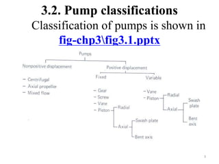
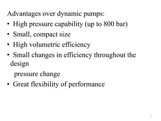
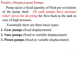
2. 3.1 Introduction
A pump is the heart of the hydraulic system and
converts mechanical energy into hydraulic energy. It
is driven by electricity or combustion engines or
other sources.
Two broad classifications:
1. Dynamic (non-positive displacement) pumps
2. Positive displacement pumps
2
4. 1. Dynamic (non-positive displacement) pumps
In the dynamic group are the centrifugal pumps.
Normally suited for low pressure and high
discharge. They are of little use in the fluid power
system.
2. Positive displacement pumps
The positive displacement type is universally used
for fluid power systems. Here a fixed amount of fluid
is forced (pushed) through the system per revolution
of pump shaft.
4
5. Advantages over dynamic pumps:
• High pressure capability (up to 800 bar)
• Small, compact size
• High volumetric efficiency
• Small changes in efficiency throughout the
design
pressure change
• Great flexibility of performance
5
6. Positive Displacement Pumps
Pump ejects a fixed quantity of fluid per revolution
of the pump shaft. All such pumps have pressure
relief valves for diverting the flow back to the tank in
case of high pressure.
Essentially there are three basic types:
1. Gear pumps (fixed displacement)
2. Vane pumps (fixed or variable displacement)
3. Piston pumps (fixed or variable displacement)
6
7. Gear pumps (fixed displacement)
a. External gear pumps
b. Internal gear pumps
c. Lobe pumps
d. Screw pumps
Vane pumps
a. Unbalanced vane pumps (fixed or variable
displacement)
b. Balanced vane pump (fixed displacement)
Piston pumps (fixed or variable displacement)
a. Axial design
b. Radial design
7
8. 3.2.1 Gear Pumps
A) External Gear Pump
Fluid flow is developed by carrying fluid between
the teeth. fig-chp3fig3.2.pptx Suction side is where
teeth come out of mesh (volume expansion)
And discharge side where teeth go into mesh
(volume decreases)
Displacement volume of pump is given by
Where: Do and Di are tip and root diameter of the gears.
Theoretical flow rate for N (rev/min)
8
)
/
(
)
( rev
m
L
D
D
V i
o
D
3
2
2
4
)
min
/
m
(
N
V
Q 3
D
t
9. Performance curves are shown in fig-
chp3fig3.3.pptx
As there is clearance at the tip of the gear teeth oil
can leak back towards the suction line, thus reducing
the actual volume flow rate. This internal leakage
called pump slippage is identified by volumetric
efficiency ηv defined as:
Higher discharge pressure will result in more
leakage thus making the volumetric efficiency lower.
9
t
a
v
Q
Q
10. Too high pressure can also damage the pump parts.
Such pressures can be due to high resistance to flow
or a closed valve in the pump outlet line. This again
emphasizes the need for relief valves.
Spur gears are noisy and helical gears are less
noisy.
But since they introduce high thrust they are
limited to low pressures (below 15 bars).
Herringbone gear pumps eliminate the thrust and run
smoothly.
10
11. B) Internal Gear Pumps
This is shown in fig-chp3fig3.4.pptx . Power is
applied to any one of the gears. The motion of the
gears forces the fluid around both sides of the
crescent seal which acts as a seal between the suction
and discharge ports.
Industrial gear pumps can run at 1500-2500rpm
with pressures to 200 bars. Flow rates up to about
400l/min
11
12. C) Lobe Pump
It operates in a fashion similar to the external gear
pump. But both lobes are driven externally so that
there is no direct contact of the surfaces. It is quieter
and has a larger volume flow rate than the other gear
pump typesfig-chp3fig3.5.pptx .
D) Gear rotor Pump (Gerotor pump)
fig-chp3fig3.6.pptx It is a form of internal gear
pump. Inner gear has one tooth less than the outer.
The inner gear is placed eccentrically with respect to
the outer and this gives rise to an alternative increase
and decrease of the
12
13. volumes of the pockets as the gears rotate. Operating
pressure range 70-140 bars and for flows up to 240
l/min.
E) Screw Pump
fig-chp3fig3.7.pptx This is an axial flow positive
displacement unit. The central rotor is the only one
driven and the two idler rotors that are in rolling
contact act as rotating seals.
• Flow rates up to 2000 l/min and pressure ranges up
to 250 bars.
13
14. 3.2.2) Vane pumps
This is shown in fig-chp3fig3.8.pptx Freely
moving (radial)vanes are located on the slots of the
cylinder. Centrifugal force keeps the vanes out
against the housing serving as a seal. Because of
eccentricity (housing forms a cam ring) the
compartments between the slots expand and contract.
The expansion assists the intake and the contraction
assists the discharge.
The eccentricity is given by
Where: Dc and Dr are cam ring and rotor diameters.
2
D
D
e r
c
14
15. Volumetric displacement per revolution
L is width of rotor.
Q can also be expressed as a function of the
eccentricity as:
Vane pumps are classified as fixed or variable
displacement and unbalanced or balanced design.
The following combinations are available:
L
)
D
D
)(
D
D
(
4
L
)
D
D
(
4
Q r
c
r
c
2
r
2
c
eL
)
D
D
(
2
Q r
c
15
16. • Fixed displacement, unbalanced design
• Fixed displacement, balanced design
• Variable displacement, unbalanced design
The vane pump shown earlier is a fixed
displacement, unbalanced design. There is
unbalanced force on the rotor which results as a side
thrust to be taken up by the bearings.
The balanced design uses two inlet (diametrically
opposed) and similarly two outlets fig-
chp3fig3.9.pptx . This will eliminate the side thrust.
The cam ring will have an elliptical shape
16
17. 3.2.3) Piston pumps
It is the reciprocating motion that gives rise to the
pumping process. A series of reciprocating pistons
are involved in this. Normally used for pressures in
excess of 200 bar.
Two basic types of piston pumps, fixed displacement:
• Axial design, pistons parallel to the cylinder block
• Radial design, pistons around the pump drive shaft
at right angles
17
18. A)Axial Design (Swash Plate Design)
In the axial design (in-line piston pump or swash
plate design), two possible arrangements are there
fig-chp3fig3.11.pptx and fig-chp3fig3.12.pptx
• Fixing the swash plate and rotating the cylinder
block (piston revolves (also reciprocating) with the
rotor)
• Rotating the swash plate and fixing the cylinder
barrel (piston only reciprocating)
The swash plate type can also be of variable
displacement by changing the offset angle by some
control system. fig-chp3fig3.13.pptx
18
19. Axial Design (Bent axis Design)
A bent axis pump fig-chp3fig3.14.pptx and fig-
chp3fig3.15.pptx reciprocates the pistons in the
rotating cylinder block through a bevel gear
mechanism (fixed displacement) or a universal joint
(variable displacement) that changes the offset angle.
fig-chp3fig3.16.pptx
19
20. The volumetric displacement and the theoretical
volume flow rate can be determined as follows.
Using fig-chp3fig3.16.pptx
tan θ = S/D
S=D tan θ
Where: S-stroke, D-piston circle diameter
Total displacement volume for Y pistons of area A
each and for one cycle
Vd=YAS = YAD tan θ
And for piston speed of N rpm:
20
min)
/
m
(
tan
DANY
N
V
Q 3
d
d
21. B)Radial Design
The operation and construction of a radial piston
pump is shown in fig-chp3fig3.17.pptx. The
pistons are in constant contact due to the centrifugal
force. The pumping action is due to the eccentricity
of the rotor with respect to the reaction ring.
In some models, the displacement can be made
variable by moving the reaction ring to change the
piston stroke.
21
22. 3.3 Pump performance
Two types of efficiencies will be considered:
volumetric efficiency and mechanical efficiency
Volumetric Efficiency, ηv
This indicates the amount of leakage that takes
place within the pump and given by
Typical values
Gear pumps: 80% to 90%
Vane pumps: 82% to 92%
Piston pumps: 90% to 98%
t
a
v
Q
Q
)
produce
should
pump
rate
(
flow
l
theoretica
)
pump
by
produced
rate
(
flow
actual
22
23. Mechanical Efficiency
This indicates the amount of energy losses that occur
for reasons other than leakage (friction and fluid
turbulence). Typically runs between 90% and 98%.
p= pressure rise across pump (Pa) ≈ pdischarge
pump theoretical flow rate (m3/s)
Ta=actual torque delivered to pump (N m)
ω=pump speed (rad/s)
a
t
m
T
Q
p
pump
to
delivered
power
actual
leakage
no
power
output
pump
t
Q
23
24. In terms of torques fig-chp3fig3.18.pptx
Ttω= ; For one cycle
The term
is a characteristic of a specific motor or pump.
a
t
m
T
T
deliverded
torque
actual
input
torque
l
theoretica
2
p
V
T
d
t
24
Q
p
T
Q
p t
t
cycle
per
nt
displaceme
2
V
or
radian
/
volume
Q D
)
(W
delivered
power
actual
Ta
25. Overall Efficiency, ηo
Overall efficiency considers all energy losses and
hence is defined as
Mathematically it can be represented as
Substituting the values
which agrees with the definition.
pump
to
delivered
power
actual
pump
by
delivered
power
actual
o
25
m
v
o
a
a
a
t
t
a
O
T
Q
p
T
Q
p
Q
Q
26. Pump Performance Comparison Factors
fig-chp3fig3.21.pptx compares various performance
factors for hydraulic pumps
Gear pumps- least expensive; lowest level of
performance; simple in design and compact in size-
makes them the most common type of pump used in
fluid power systems.
Vane pumps- efficiencies and cost fall between gear
and piston pumps-last for long time; needs clean oil
with good lubricity
Piston pumps- most expensive; provide the highest
level of overall performance.
26
27. Pump Selection
• Select actuator (cylinder or motor) based on the load
• Determine flow-rate requirement
• Select system pressure
• Determine pump speed and select prime mover
• Select the pump type
Finally, optimization may be required for the
system to operate at minimum cost while satisfying
the design requirements.
27