Downloaded 1,470 times

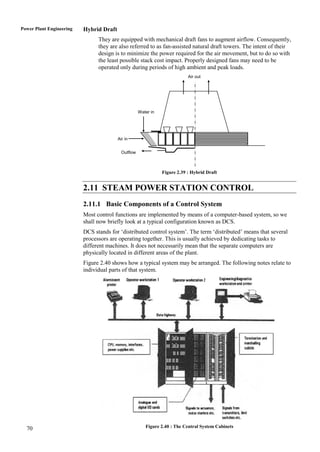
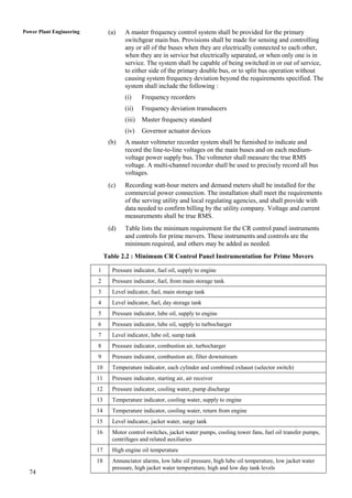
![structure. The other part of the feedforward is a filter which ensures that the feedwater Steam Power Plant
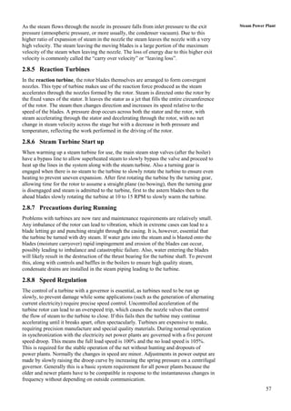
and the fuel are fed to the boiler in a dynamically optimal way thus ensuring that no
control fault arise – neither for the temperature nor for the live steam pressure during
load changes. Because of the presence of large time constants in the boiler due to the
large metal masses and delays in the firing system there is a limitation to how hard the
feedback loops can be tuned. This implies that if it is required to operate the plant at
large load gradients or it is desired to stress the plant as little as possible the presence
and correct tuning of the feedforward part is very important.
2.11.8 Feedback Control
The purpose of the feedback control is to reject disturbances which mostly originate
from the furnace during normal operation (mainly due to changes in fuel flow and
quality). The feedback control consists of a temperature and a pressure control loop. The
enthalpy at the evaporator outlet is PI controlled in the inner loop. The reason for
controlling the enthalpy at the evaporator outlet instead of the steam temperature is that
in this way non-linearities originating from the steam characteristics are automatically
incorporated. The proportional and integral part of the PI controllers must be scheduled
according to the actual load point since the gain and time constant of the boiler are
highly dependent on the load point (because of the change in steam flow).
The live steam pressure is controlled by a single PID-based control loop. For this loop
the parameters of the PID controller must also be dependent on the actual load point.
Since the boiler process is fully connected (the feedwater flow and the fuel flow affect
both the steam temperature and the live steam pressure) it is important to introduce a
decoupling network between the two feedback loops. Consequently, the two feedback
loops can be tuned independently and with as high a bandwidth as possible since no
oscillatory modes will arise between the two feedback loops.
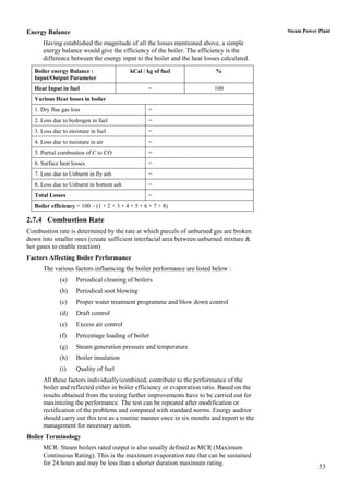
2.11.9 Advanced Evaporator Control
To estimate the boiler dynamics for the purpose of performing model-based tuning, an
open-loop test must be performed or estimation performed in closed loop. Both tasks
might be difficult. Furthermore, for plant equipped with non-programmable control
systems the implementation of the conventional way is quite tedious. To overcome these
difficulties, an alternative concept has been developed. The objective is to improve the
load-following capability of existing power plant units. During fast load changes, the
major problem is to keep certain critical variables (e.g. steam temperature and steam
pressure) within predefined limits, as excessive deviations will seriously affect the
lifetime of the components or cause a trip. One way of improving the load-following
capability of power plants is to improve the control of these critical variables.
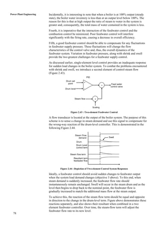
Load demand
Scheduled
LQG controller
[0:1]
uadd
y ref e - y
Existing boiler u Boiler
control system
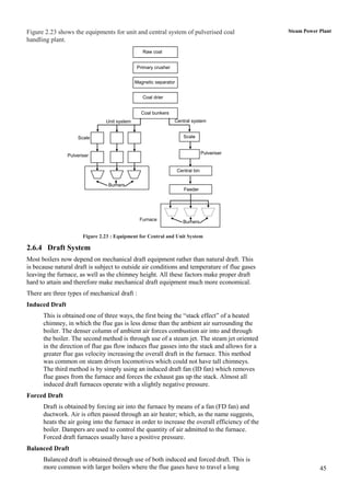
- +
Figure 2.47 : Scheduled LQG Controller with Feedwater Acton from Load Demand Signal,
as a Complement to an Existing Boiler Control System 81](https://image.slidesharecdn.com/powerplant-120505223049-phpapp01/85/Power-plant-61-320.jpg)


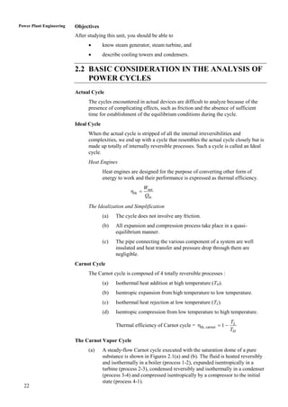
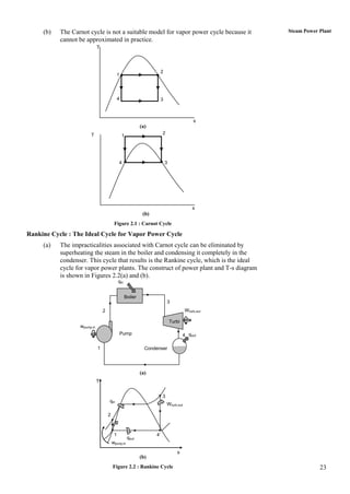
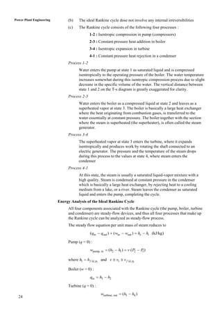
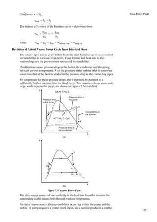
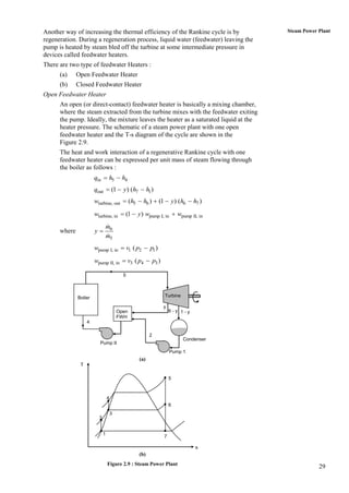
This document describes the ideal Rankine cycle, which is the thermodynamic cycle that forms the basis for steam power plants. It consists of four processes: 1) isentropic compression of water in a pump, 2) constant pressure heat addition to produce high-temperature, high-pressure steam in a boiler, 3) isentropic expansion of the steam in a turbine to produce work, and 4) constant pressure heat rejection in a condenser to return the steam to liquid water. The Rankine cycle is the idealized model that closely approximates the actual thermodynamic cycle used in steam power plants to convert heat into useful work.


