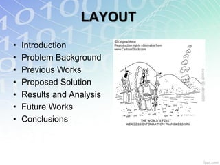
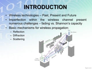
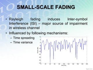
![INTRODUCTION
• Type of imperfections:
– Large-scale fading:
• Power varies gradually
• Over large distance, terrain contours
• Determine by path profile and antenna displacement
– Small-scale fading:
• Small changes of the reflected, diffracted and scattered
signals
• Resulting in vector summation of destructive/ constructive
interference at Rx, known as multipath wave
• Rapid changes of amplitudes, phase or angle
• Also known as Rayleigh fading [1] or frequency selectivity
[1] J.G. Proakis. Digital Communications. Fourth Edition, The McGraw-Hill Companies, 2001](https://image.slidesharecdn.com/rosdiadeenordin-facultyseminarfinal-121106011045-phpapp01/85/Spatial-Interference-and-It-s-Effect-Towards-the-Performance-of-4G-Network-4-320.jpg)
![MITIGATION STRATEGIES
• Introducing diversity [2]:
– Time: coding, interleaving, adaptive modulation,
equalization (linear/ non-linear)
– Spatial: multiple antenna, involves combining
methods
– Multiuser: exploit channel quality from different users
– Cooperative: relay
– Frequency: spread spectrum (DS and FH), SC-FDE
[3], OFDM [4]
[2] B. Sklar. “Rayleigh Fading Channels in Mobile Digital Communications Systems. Part II: Mitigation”, IEEE
Communications Magazine, Vol. 35, No. 7, pp. 102-109, July 1997
[3] H. Sari, G. Karam, and I. Jeanclaude. “Transmission techniques for digital terrestrial TV broadcasting”. IEEE
Communications Magazine, Vol. 33, No. 2, pp. 100-109, Feb., 1995.
[4] R. van Nee and R. Prasad. OFDM for Wireless Multimedia Communications. Artech House Publishers, 2000.](https://image.slidesharecdn.com/rosdiadeenordin-facultyseminarfinal-121106011045-phpapp01/85/Spatial-Interference-and-It-s-Effect-Towards-the-Performance-of-4G-Network-6-320.jpg)
![MIMO
• Another potential technology for future 4G. Have been
around since 1970 [5]
• Leveraging multipath – exploiting fading (instead of
mitigating) for the benefit of MIMO users
• CMIMO = min(Nt,Nr). Increasing the number of Tx, Rx
antenna allows more data to be transmitted
Radio Channel, H
x1 1 1 y1 ŷ1
Tx1 Rx1
2
x2 2 y2 ŷ2
Tx2 Rx2 MIMO
Processing
x Nt Nt Nr yNr ŷNr
Tx Nt Rx Nr
[5] A.R. Kaye and D.A. George. “Transmission of multiplexed PAM signals over multiple channel and diversity systems,”
IEEE Trans. on Comms. Technology. Vol. COMM-18, pp. 520-526, Oct. 1970](https://image.slidesharecdn.com/rosdiadeenordin-facultyseminarfinal-121106011045-phpapp01/85/Spatial-Interference-and-It-s-Effect-Towards-the-Performance-of-4G-Network-10-320.jpg)
![MIMO
• Can takes many forms for different type of configurations
• SISO vs. MIMO capacity [6]:
2 SNR
C SISO log 2 (1 SNR H ) vs. C MIMO log 2 det I N HH*
Nt r
• Two forms of MIMO:
– Space-Time Code (STC)
– Spatial Multiplexing (SM)
[6] D. Gesbert, M. Shafi, D.S Shiu, P.J. Smith, and A. Naguib. “From theory to practice: an overview of MIMO space-time
coded wireless systems”, Tutorial paper. IEEE Journal on Selected Areas in Communications (JSAC), Vol. 21, No. 3, pp.
281-302, Apr. 2003](https://image.slidesharecdn.com/rosdiadeenordin-facultyseminarfinal-121106011045-phpapp01/85/Spatial-Interference-and-It-s-Effect-Towards-the-Performance-of-4G-Network-11-320.jpg)
![MIMO – STC
• STC aim to reduce the effect of fading by:
– Achieve maximum antenna diversity
– Improve wireless link reliability
• Combines the use of channel coding and multiple
transmit antennas
• Achieve spatial diversity at the expense of throughput
• Common forms of STC:
– Space-Time Trellis Code (STTC)
– Space-Time Block Code (STBC)
– Space-Frequency Block Code (SFBC)
• Practical and common representation of STBC was
introduced by Alamouti [7]
[7] S. Alamouti, “A simple transmit diversity technique for wireless communications”, IEEE Journal on Selected
Areas in Communications (JSAC), Vol. 16, No. 8, pp. 1451-1458, Oct. 1998](https://image.slidesharecdn.com/rosdiadeenordin-facultyseminarfinal-121106011045-phpapp01/85/Spatial-Interference-and-It-s-Effect-Towards-the-Performance-of-4G-Network-12-320.jpg)
![MIMO – SM
• Capable of increasing the data rate by higher spectral
efficiencies at no additional power or bandwidth
• Dividing the high rate data stream input into parallel
independent data streams.
• Thus, increased the nominal spectral efficiencies by a
factor of Nt.
• V-BLAST [8] generally regarded as the common form of
SM
Antenna Index Antenna Index
Interference
a b c d Nulled
a a a a
Wasted
a b c d
b b b b
a b c d
c c c c
Wasted
a b c d
Time d d d d
Cancelled Detection Order Time
D-BLAST V-BLAST
[8] G. J. Foschini, “Layered Space-Time Architecture for Wireless Communication in a Fading Environment when Using
Multielement Antennas,” Bell Labs Tech. J., pp. 41–59, Autumn 1996](https://image.slidesharecdn.com/rosdiadeenordin-facultyseminarfinal-121106011045-phpapp01/85/Spatial-Interference-and-It-s-Effect-Towards-the-Performance-of-4G-Network-13-320.jpg)

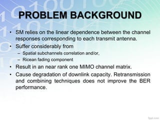
![PROBLEM BACKGROUND
• Most MIMO implementations consider ideal propagation
conditions, i.e. uncorrelated channel
• For realistic approach, spatial correlation does exist
between antenna pairs – affects MIMO capacity
• The effect is known as self-interference [6]
12
RBS=0.0,RMS=0.0
RBS=0.4,RMS=0.4
10
Spatial layer 1 RBS=0.5,RMS=0.5
T1 R1 RBS=0.0,RMS=0.9
Spatial layer 2 8 RBS=0.9,RMS=0.0
capacity (bps/Hz)
Interference RBS=0.9,RMS=0.9
from T2 6 RBS=1.0,RMS=1.0
BS Interference MS
from T1 4
T2 Spatial layer 1 R2
Spatial layer 2
2
0
-10 -5 0 5 10 15 20
SNR (dB)
[6] D. Gesbert, M. Shafi, D.S Shiu, P.J. Smith, and A. Naguib. “From theory to practice: an overview of MIMO space-time
coded wireless systems”, Tutorial paper. IEEE Journal on Selected Areas in Communications (JSAC), Vol. 21, No. 3, pp.
281-302, Apr. 2003](https://image.slidesharecdn.com/rosdiadeenordin-facultyseminarfinal-121106011045-phpapp01/85/Spatial-Interference-and-It-s-Effect-Towards-the-Performance-of-4G-Network-16-320.jpg)
![PROBLEM BACKGROUND
• Factors contribute towards self-interference:
– Insufficient antenna separation
– Small scattering angle, e.g. AoA, AoD, etc
– Height of BS antennas
– Separation between Tx and Rx antenna
• Design antenna based on degree of correlation [9], e.g.
100 separation and wider angle (max. 900)
• Not possible due to RF planning, safety, environmental
and installation issue
several km
small small
[9] W. Lee, "Effects on Correlation between Two Mobile Radio Base-Station Antennas," IEEE Transactions on
Communications, Vol.21, No.11, pp. 1214-1224, Nov 1973](https://image.slidesharecdn.com/rosdiadeenordin-facultyseminarfinal-121106011045-phpapp01/85/Spatial-Interference-and-It-s-Effect-Towards-the-Performance-of-4G-Network-17-320.jpg)
![PREVIOUS WORKS
• Efficient design techniques for MIMO antenna
implementation
– Antenna separation
– Orthogonality: angle, space, polarization
• Challenges:
– Environmental and safety concern
– Array blindness
– Reduction of antenna effective gain
– „Keyhole‟ or „pinhole‟ effect [10]
[10] D. Chizhik, G. J. Foschini, and R.A. Valenzuela, “Capacities of multi-element transmit and receive
antennas: Correlations and Keyholes,” Electronic Letters, Vol. 36, pp. 1099–1100, June 2000](https://image.slidesharecdn.com/rosdiadeenordin-facultyseminarfinal-121106011045-phpapp01/85/Spatial-Interference-and-It-s-Effect-Towards-the-Performance-of-4G-Network-18-320.jpg)
![PREVIOUS WORKS
• Optimum power allocation scheme – known CSI at the
Tx via SVD [11]
• Singular values as the decision criteria for power
allocation – to identify effective independent channel
• Challenges:
– Inaccurate CSI in fast fading channels
– Different eigenvalues in each channel – errors in selection
criteria
– High spatial correlation low eigenvalues low gain (power
loss)
[11] R.R. Ramirez and F. De Flaviis, "A mutual coupling study of linear and circular polarized microstrip antennas for
diversity wireless systems", IEEE Transactions on Antennas and Propagation, Vol. 51, No. 2, pp. 238-248, Feb. 2003](https://image.slidesharecdn.com/rosdiadeenordin-facultyseminarfinal-121106011045-phpapp01/85/Spatial-Interference-and-It-s-Effect-Towards-the-Performance-of-4G-Network-19-320.jpg)
![PREVIOUS WORKS
• Enhanced version of [11]: antenna selection + power
allocation [12]
• Using the correlation matrix, instead of CSI as feedback:
less overhead, low feedback req. and faster allocation
process
• „Water-filling‟ approach
• Challenges:
• Requires continuous bit assignment
• But modulations is discrete; can be
overcome by AMC
• At the expense of data rate loss
[12] M.T. Ivrlac, W. Utschick, J.A. Nossek, "Fading correlations in wireless MIMO communication systems",
IEEE Journal on Selected Areas in Communications, Vol. 21, No. 5, pp. 819- 828, June 2003](https://image.slidesharecdn.com/rosdiadeenordin-facultyseminarfinal-121106011045-phpapp01/85/Spatial-Interference-and-It-s-Effect-Towards-the-Performance-of-4G-Network-20-320.jpg)
![PREVIOUS WORKS
• Constellation multiplexing [13]: the use of power scaling
by scaling down the desired M-QAM constellation size
• Adjust the power and phase of the input constellations
• In a 16-QAM, superposed of 2×4-QAM
s2
signals), scaled down to ¼ with BER te
xt
te
xt
te
xt
te
xt
loss of 4 dB te te te
s1
te
xt xt xt xt
• But, requires one transmit antenna to
te te te te
Tx and Rx xt xt xt xt
• Only „dual mode‟ operation te
xt
te
xt
te
xt
te
xt
[13] J. Akhtar, D. Gesbert, "A closed-form precoder for spatial multiplexing over correlated MIMO channels", IEEE
Global Telecommunications Conference, 2003. GLOBECOM '03, Vol. 4, pp. 1847-1851, Dec. 2003](https://image.slidesharecdn.com/rosdiadeenordin-facultyseminarfinal-121106011045-phpapp01/85/Spatial-Interference-and-It-s-Effect-Towards-the-Performance-of-4G-Network-21-320.jpg)
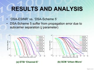
![PREVIOUS WORKS
• Subcarrier allocation scheme based on the knowledge of
the adjacent spatial sub-channels – DSA Scheme 5 [14]
• Avoid selection of (i) similar subcarrier from the adjacent
spatial subchannel, and (ii) the near subcarriers
• Depends on the separation between current and next
allocated subcarrier, j
• Depends on the channel model profile
The queue by metric of channel gain of
subcarrier at the certain subchannel A and B
21 38 89 128 328 437
Previously considered
spatial subchannel
(subchannel A)
21 26 30 71 105 128
The considered spatial
The allocated subchannel for the same
subcarrier user (subchannel B)
[14] Y. Peng, S. Armour, A. Doufexi, J. McGeehan, “An Investigation of Optimal Solution for Multiuser Sub-carrier
Allocation in OFDMA Systems”, IEEE Multi-Carrier Spread-Spectrum Workshop (MCSS): Proceedings from the 5th
International Workshop: pp. 337-344. Germany, Sep. 2005](https://image.slidesharecdn.com/rosdiadeenordin-facultyseminarfinal-121106011045-phpapp01/85/Spatial-Interference-and-It-s-Effect-Towards-the-Performance-of-4G-Network-22-320.jpg)
![PREVIOUS WORKS
• Swapping of subcarriers between users, known as
MGSS [15] to achieve max. power gain
• Total perceived gain as the performance metric
• Involved two stages:
– Initial allocations: fast & rough 0
10
version of the allocation matrix
– Sort-swap: iterative process to
Bit Error Rate (BER)
-1
10
refine the allocation
• However, MGSS has poor -2
10 Uncorr
HL
HH
performance against self- CH
Full
-3
interference 10
-5 0 5 10 15 20
Signal-to-Noise Ratio (SNR) in dB
25 30
• Modification is required
[15] S. Pietrzyk, G.J.M Janssen, “Multiuser subcarrier allocation for QoS provision in the OFDMA systems”, IEEE
56th Vehicular Technology Conference, 2002. VTC 2002-Fall, Vol.2, pp. 1077- 1081, Sept. 2002](https://image.slidesharecdn.com/rosdiadeenordin-facultyseminarfinal-121106011045-phpapp01/85/Spatial-Interference-and-It-s-Effect-Towards-the-Performance-of-4G-Network-23-320.jpg)
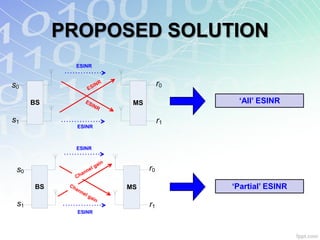
![PROPOSED SOLUTION
• OFDMA allows multiple users to Tx simultaneously on
different subcarriers by exploiting channel fading
• Initial work done based on SISO transmission [16]
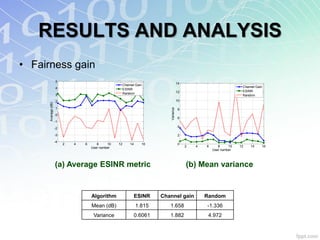
• ESINR as performance metric, known as DSA-ESINR
• Involves sorting, comparing and simple arithmetic
• Ranks users from lowest to highest ESINR – fairness
MMSE filter
q= spatial layer Main spatial layer
2
Gk H k qq Es
q
ESINRk 2 2 2
Gk H k Es Gk Gk N
Channel Gain
qj, j q qq qj, j q
M A
FD
k= subcarrier index Knowledge of TDMA
self-interference
[16] A. Doufexi and S. Armour, "Design Considerations and Physical Layer Performance Results for a 4G OFDMA System
Employing Dynamic Subcarrier Allocation", IEEE 16th International Symposium on Personal, Indoor and Mobile Radio
Communications, 2005. PIMRC 2005, Vol. 1, pp. 357-361, Sept. 2005](https://image.slidesharecdn.com/rosdiadeenordin-facultyseminarfinal-121106011045-phpapp01/85/Spatial-Interference-and-It-s-Effect-Towards-the-Performance-of-4G-Network-24-320.jpg)
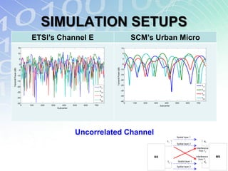
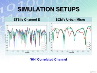
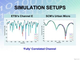
![SIMULATION SETUPS
• Nsub= 768, NFFT= 1024 for 16 users, 48 subcarriers per
user, 2×2 MIMO configuration
• Six MCS schemes, consists of BPSK, QPSK, 16-QAM
and 64-QAM with ½ or ¾ coding rate 0.9
1
0.8
• Two channel models: 0.7
Normalised power
0.6
– ETSI HiperLAN „Channel E‟ [17]
0.5
0.4
0.3
– 3GPP-SCM „Urban Micro‟ [18] 0.2
0.1
HIPERLAN ‘E’
0 200 400 600 800 1000 1200 1400 1600 1800
Parameters Urban Micro Excess delay (ns)
1
Environment Large open space NLOS Outdoor urban NLOS 0.9
0.8
Bandwidth 100 MHz 5 MHz
0.7
Normalised power
Excess Delay Spread 1760 ns 923 ns 0.6
0.5
Mean Delay Spread 250 ns 251 ns 0.4
Carrier Frequency 5 GHz 2 GHz 0.3
0.2
0.1
[17] J. Medbo and P. Schramm, "Channel Models for HIPERLAN/2," ETSI/BRAN 200 300 400 500 600 700 800 900 1000
Excess delay (ns)
document no. 3ERI085B, 1998.
[18] 3GPP, “Spatial channel model for MIMO simulations”, TR 25.996 V7.0.0, 3GPP,
2007. [Online]. Available: http://www.3gpp.org/](https://image.slidesharecdn.com/rosdiadeenordin-facultyseminarfinal-121106011045-phpapp01/85/Spatial-Interference-and-It-s-Effect-Towards-the-Performance-of-4G-Network-26-320.jpg)
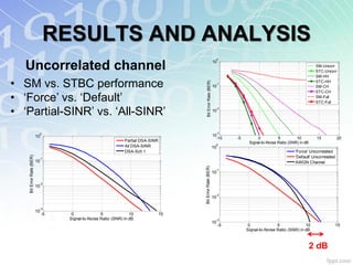
![SIMULATION SETUPS
• Correlation model based on Kronecker product,
RMIMO=RMS RBS [19]
Correlation
• „Fully‟ correlated channel: worst case
Correlation
Coefficient
Modes
RBS RMS
scenario, i.e. SISO case
„Full‟ 0.99 0.99
• Uncorrelated channel: „ideal‟ channel „CH‟ 0.96 0.96
„HH‟
condition 0.91 0.91
„HL‟ 0.91 0.30
• Issue: how uncorrelated is an Uncorrelated 0.00 0.00
uncorrelated channel? Correlation
Correlation
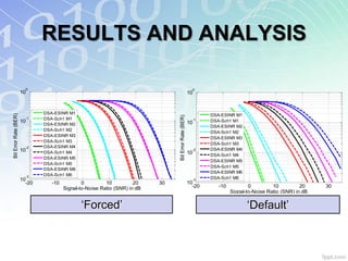
• Uncorrelated: „Default‟ vs „Forced‟
Coefficient
Modes
RBS RMS
– ‘Default’: Generated by the channel models „Default‟ 0.45 0.32
– ‘Forced’: No effect of self-interference „Forced‟ 0.00 0.00
[19] K.I. Pedersen, P.E. Mogensen, B.H. Fleury, “Spatial Channel Characteristics in Outdoor Environments and Their
Impact on BS antenna System Performance”, IEEE Proc. Vehicular Technology Conference. VTC ’98, Vol. 2, pp. 719-724,
May 1998.](https://image.slidesharecdn.com/rosdiadeenordin-facultyseminarfinal-121106011045-phpapp01/85/Spatial-Interference-and-It-s-Effect-Towards-the-Performance-of-4G-Network-27-320.jpg)
![LTE FUNDAMENTALS
• Advantages of LTE:
– Performance: @ 20 MHz BW offering up to 50 Mbps (UL) and
100 Mbps (DL)
– Reduced latency: „flat‟ network architecture
– Improved spectrum flexibility: 1.25 to 20 MHz
– Operational cost: SON
• Work based on 3GPP-LTE Rel. 8 [20]
• MIMO-OFDMA as the potential candidate
for 4G downlink technology
[20] Technical Specification Group Radio Access Network; (E-UTRA) and (EUTRAN): Physical Channels and
Modulation‟, 3GPP TS 36.211 V8.4.0, Sept 08. [Online]. Available: http://www.3gpp.org/ftp/Specs/html-info/36211.htm](https://image.slidesharecdn.com/rosdiadeenordin-facultyseminarfinal-121106011045-phpapp01/85/Spatial-Interference-and-It-s-Effect-Towards-the-Performance-of-4G-Network-41-320.jpg)
![LTE FUNDAMENTALS One radio frame, Tt= 307,200Ts= 10 ms
One subframe, Tslot= 15,360Ts = 0.5 ms
Slot #0 Slot #1 Slot #19
• Resource block (RB): a group of 12
One slot
Resource Block
NRB= Nsub×Nsym
resource elements
subcarriers, smallest element in LTE
OFDMA Subcarrier (Frequency)
• Short and long Cyclic Prefix (CP)
• 15 MCS schemes [20], only six
Resource Element
Nsub NRB ×Nsub
considered for simulation
Coding Coded bits Data bits Nominal Bit
Mode Modulation
Rate per carrier per time slot Rate (Mbps)
Nsym
1 QPSK ½ 2 7,600 15.2
OFDMA Symbol (Time)
2 QPSK ¾ 2 11,400 22.8
3 16-QAM ½ 4 15,200 30.4
1 frame (10 ms)
4 16-QAM ¾ 4 22,800 45.6
5 64-QAM ½ 6 22,800 45.6 1 subframe (1 ms) 1 slot (0.5 ms)
6 64-QAM ¾ 6 34,200 68.4 0 1 2 3 10 11 19
0 1 2 3 4 5 6 0 1 2 3 4 5 6
7 OFDM symbols
(short cyclic prefix)
cyclic prefixes
LTE generic frame structure](https://image.slidesharecdn.com/rosdiadeenordin-facultyseminarfinal-121106011045-phpapp01/85/Spatial-Interference-and-It-s-Effect-Towards-the-Performance-of-4G-Network-42-320.jpg)
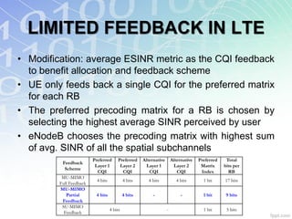
![LIMITED FEEDBACK IN LTE
• Capacity gain can be achieved when Nt antennas
communicate with k users: MU-MIMO [21], another form
of SDMA
• Benefit from CSIT. Can be achieved by precoding
technique at the expense of feedback overhead –
challenging especially in a fast fading channel
• Limited
Rx1
feedback: provides
„incomplete‟ info on the channel Tx1 RxN UE1
Rx1
• Three types of feedback Tx2
RxN UE2
schemes in LTE: CQI, RI and eNodeB
Rx1
PMI TxM
RxN
UEk
[21] H. Weingarten, Y. Steinberg, S.Shamai, “The capacity region of the Gaussian MIMO broadcast channel”, IEEE
Proc. International Symposium on Information Theory, Vol. 52, No. 9, pp. 3936-3964, Sept. 2006](https://image.slidesharecdn.com/rosdiadeenordin-facultyseminarfinal-121106011045-phpapp01/85/Spatial-Interference-and-It-s-Effect-Towards-the-Performance-of-4G-Network-43-320.jpg)
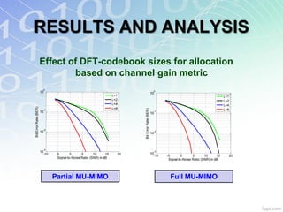
![LIMITED FEEDBACK IN LTE
• Precoding to achieve accurate CSIT
• DFT-based codebook precoding is considered [22]
• Amount of feedback increased as the spatial
subchannels, Q and codebook size, L increased
[22] D. Yang; L. Yang, L. Hanzo, “DFT-Based Beamforming Weight-Vector Codebook Design for Spatially Correlated
Channels in the Unitary Precoding Aided Multiuser Downlink”, 2010 IEEE International Conference on Communications.
ICC 2010, pp. 1-5, May 2010](https://image.slidesharecdn.com/rosdiadeenordin-facultyseminarfinal-121106011045-phpapp01/85/Spatial-Interference-and-It-s-Effect-Towards-the-Performance-of-4G-Network-45-320.jpg)


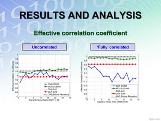
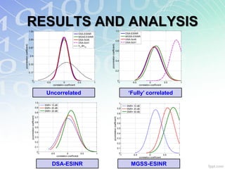
The document discusses spatial interference and its effect on future 4G wireless networks. It provides background on the problem of spatial interference in multiple-input multiple-output (MIMO) systems which can degrade capacity. Previous works that attempted to address this issue through techniques like antenna separation, optimum power allocation, and subcarrier allocation are summarized. The proposed solution will look to further mitigate the effects of spatial interference in orthogonal frequency-division multiple access (OFDMA) systems.