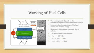
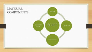
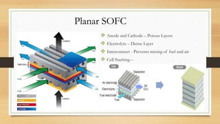
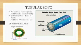
• PRESENTED BY:
1.SHASHANK REDDY- BT16MME044
2.RITAM GHOSH- BT16MME055
3.SANYAM TOTADE- BT16MME065
4.SUMANSHU SETHI- BT16MME075
Introduction
• The increasing population has led to consumption of fuel at an unimaginable rate in past few
decades.
• As a result, world is facing the problem of exhaustion of non renewable resources of energy.
• The scientists are thus compelled to develop some alternative energy resource for the future
generation.
• Fuel cells may serve this purpose .
• According to reports from Fuel Cell Today (FCT) Fuel Cell 2000 ,fuel cells can offer clean ,
reliable and efficient power to almost all electrical power device.
• The presentation mainly comprises of the development of fuel cells ,especially SOFC which can
serve as a source of clean ,efficient and reliable source of energy.
Contents
• Fossil Fuels and their alternatives.
• World Energy Needs.
• Development in Fuel cells over the
years.
• Description of Fuel Cells
• Geometric Designs of SOFCs.
• Types of SOFC designs
• SOFC materials
• Perovskite Structure.
• Trend in SOFCs.
• Nano- Structured SOFCs.
• Performance of SOFC
• Efficiency of SOFC.
• Applications of SOFCs.
Fossil Fuel and Alternate Energy Resources.
The consumption of energy in world.
Worlds Annual Energy Needs
Initial Achievements of Fuel Cells.
Working of Fuel Cells
• The working mainly depends on the
transportation process in electrochemical reaction.
• It converts the chemical energy of fuel and
oxidant into electrical energy .
• Hydrogen is fed to anode , oxygen is fed to
cathode.
• The electrochemical reactions are:
1. H2 2H+ +2e-
2. 1/2 O2 +2e- O-2
3. H2 + 1/2O2 H2O
SOFC
ANODE
CATHODE
INTERCONNECTS
ELECTRO
LYTE
MATERIAL
COMPONENTS
ANODE (Fuel Electrode)
• In contact with Fuel
• Negatively Charged
• Oxidation Reaction occurs – catalyses oxygen-fuel
reaction
• Anode layer must be porous – to allow fuel to reach
towards electrolyte
• It should be conductive in nature – to allow flow of
electrons
• Anode in SOFC - Thickest and strongest layer-
Provides mechanical support
• Most common anode material –> Cermet with Ni –>
Ex : Ni-YSZ(Yttria-Stabilized Zirconia)
CATHODE(Air Electrode)
• In contact with Air(Oxygen)
• Positively Charged
• Reduction Occurs
• Thin porous layer
• Most common cathode materials
– Ca or Sr-doped LaMnO3
– Lanthanum Strontium Manganite(LSM)
ELECTROLYTE
• Dense layer of ceramic that conducts oxygen
ions
• Has low electronic conductivity (– to minimise
leakage) but high protonic conductivity
• Thin layer – to reduce internal cell resistance
• Example- 8YSZ(8% Yttria-Stabilized Zirconia)
, 9ScSZ(Scandia-Stabilized Zirconia)
INTERCONNECT
• Metallic or Ceramic layer between each
cell
• Connects cells in series
• 95Cr-5Fe alloy is used as interconnect for
8YSZ
GEOMETRICAL DESIGN
Desired properties
Required performance
Effective cost
IMPORTANCE OF DESIGN
(Following things depend on design of SOFC)
Geometrical Design-Types
TYPES OF SOFCs
TUBULAR
PLANAR
MONOLITHIC
ROLL
 Anode and Cathode – Porous Layers
 Electrolyte – Dense Layer
 Interconnect - Prevents mixing of fuel and air
 Cell Stacking –
Planar SOFC
 Air Electrode – Cathode(Inside)
Fuel Electrode – Anode(Outside)
 Air(Oxidant) Flows – Inside of
the tube
Fuel Flows - Outside of the tube
CROSS-SECTIONAL VIEW
TUBULAR SOFC
SOFCs Material Structures
• Ceramics materials have proven their great enhancement in application of
SOFCs for both electrodes and electrolyte.
• Out of the many ceramic structures, the structures which stand out as the
most applicable materials for SOFCs are:
1. Perovskite structure.
2. Fluorite structure.
Perovskite Structures
• A perovskite is any material with the same type of crystal structure as
calcium titanium oxide (CaTiO3), known as the perovskite structure, or
A2+B4+X2−
3 with the oxygen in the face centres.
• Perovskites used for SOFCs can be classified into two types:
1. Single Perovskites.
2. Double Perovskites.
Single Perovskites
• In single Perovskites, oxygen ions are
arranged in a closed packed structure with the
metal ions occupying the interstices.
• The A-sites are typically occupied by trivalent
or divalent cations such as the Lanthanides or
alkaline earth. The B-sites are occupied by
transition metals usually taking valence 3+ or
4+ to electronically balance the compounds.
Double Perovskites
• The double perovskite structure is
basically chemically manipulated by
replacing the ion B sites to be BB’
positions which can be explained by
the basic double perovskite structure-
formula A2BB’O6.
• Properties include half-metallicity, high
temperature ferrimagnetism, and a rich
variety of magnetic interactions.
Fig: Example of double Perovskite Structure-
Sr2NiIrO6
• Ordering schemes in perovskites, for B-
site ordering in A2BB’X6 perovskites
and for A-site ordering in AA’B2X6
perovskites
SOFCs Trend From Macro to Nano-Structured
Level
• Because of the necessity of renewable, efficient sources of energy, there have been development in the
SOFCs so that it can be applicable to various aspects ranging from conventional applications to Nano-scale
applications.
• Techniques have been developed to increase the efficiency of the SOFCS by imposing slight changes in the
composition of the electrodes or electrolyte.
• Some of these developments are:
1. Improve the catalytic activities of conventional SOFC anodes.
2. Stack design as a significant issue for handling the technology of fuel cell.
3. The micro-solid oxide fuel cell has shown a big potential in the application of portable electronic devices
with a noticeable good performance at temperature ranges from 700°C to 300°C.
Nano-structured SOFCs
• The infiltration of nanoscale
particles.
• Formation of connected networks,
into solid oxide fuel cell electrodes.
Examples of Micro- structured SOFCs
SOFC’s Performance
• Obtained by methods:
• Electrochemical Impedance Spectroscopy(EIS)
• DC conductivity measurements
• I-V curves and related power density
• Binding energy measurements using X-ray photo electronic spectroscopy
• Also obtained by calculating:
V=E(thermodynamic)- ŋ(activation)- ŋ(ohmic)-ŋ (concentration)
SOFC’s Efficiency
• Highly efficient service
• Excellent performance
• Lower temperature SOFC-increased
efficiency
• Efficiency α 1/Temperature
Applications of SOFC’s
• Large and small stationary power generation
• Cogeneration applications
e.g: Combined Heat and Power(CHP)
Gas turbine
• Military applications
• Industrial applications
• Transportation applications
Conclusion
• The main aim of this report was to develop different materials for fuel cells
which serves as an alternate source of power.
• The most essential observation here about SOFCs is their various
geometrical types which can be adaptable to the related applications.
• Advantages:
1. Efficient.
2. Scalable.
3. Friendly to Environment
Disadvantages:
1. High Cost.
2. Complex Manufacturing.
3. Fuel Handling and Utilisation.
References
• https://arxiv.org/abs/1801.07078
• http://www.cpfs.mpg.de/2486283/Double-perovskites
• https://pubs.acs.org/doi/abs/10.1021/nl071007i
• US Department of Energy(DOE)
• osakagas.co.jp
• americanhistory.si.edu

Solid Oxide Fuel Cells

  • 1.
    • PRESENTED BY: 1.SHASHANKREDDY- BT16MME044 2.RITAM GHOSH- BT16MME055 3.SANYAM TOTADE- BT16MME065 4.SUMANSHU SETHI- BT16MME075
  • 2.
    Introduction • The increasingpopulation has led to consumption of fuel at an unimaginable rate in past few decades. • As a result, world is facing the problem of exhaustion of non renewable resources of energy. • The scientists are thus compelled to develop some alternative energy resource for the future generation. • Fuel cells may serve this purpose . • According to reports from Fuel Cell Today (FCT) Fuel Cell 2000 ,fuel cells can offer clean , reliable and efficient power to almost all electrical power device. • The presentation mainly comprises of the development of fuel cells ,especially SOFC which can serve as a source of clean ,efficient and reliable source of energy.
  • 3.
    Contents • Fossil Fuelsand their alternatives. • World Energy Needs. • Development in Fuel cells over the years. • Description of Fuel Cells • Geometric Designs of SOFCs. • Types of SOFC designs • SOFC materials • Perovskite Structure. • Trend in SOFCs. • Nano- Structured SOFCs. • Performance of SOFC • Efficiency of SOFC. • Applications of SOFCs.
  • 4.
    Fossil Fuel andAlternate Energy Resources. The consumption of energy in world.
  • 5.
  • 6.
  • 8.
    Working of FuelCells • The working mainly depends on the transportation process in electrochemical reaction. • It converts the chemical energy of fuel and oxidant into electrical energy . • Hydrogen is fed to anode , oxygen is fed to cathode. • The electrochemical reactions are: 1. H2 2H+ +2e- 2. 1/2 O2 +2e- O-2 3. H2 + 1/2O2 H2O
  • 9.
  • 10.
    ANODE (Fuel Electrode) •In contact with Fuel • Negatively Charged • Oxidation Reaction occurs – catalyses oxygen-fuel reaction • Anode layer must be porous – to allow fuel to reach towards electrolyte • It should be conductive in nature – to allow flow of electrons • Anode in SOFC - Thickest and strongest layer- Provides mechanical support • Most common anode material –> Cermet with Ni –> Ex : Ni-YSZ(Yttria-Stabilized Zirconia) CATHODE(Air Electrode) • In contact with Air(Oxygen) • Positively Charged • Reduction Occurs • Thin porous layer • Most common cathode materials – Ca or Sr-doped LaMnO3 – Lanthanum Strontium Manganite(LSM)
  • 11.
    ELECTROLYTE • Dense layerof ceramic that conducts oxygen ions • Has low electronic conductivity (– to minimise leakage) but high protonic conductivity • Thin layer – to reduce internal cell resistance • Example- 8YSZ(8% Yttria-Stabilized Zirconia) , 9ScSZ(Scandia-Stabilized Zirconia) INTERCONNECT • Metallic or Ceramic layer between each cell • Connects cells in series • 95Cr-5Fe alloy is used as interconnect for 8YSZ
  • 12.
    GEOMETRICAL DESIGN Desired properties Requiredperformance Effective cost IMPORTANCE OF DESIGN (Following things depend on design of SOFC)
  • 13.
    Geometrical Design-Types TYPES OFSOFCs TUBULAR PLANAR MONOLITHIC ROLL
  • 14.
     Anode andCathode – Porous Layers  Electrolyte – Dense Layer  Interconnect - Prevents mixing of fuel and air  Cell Stacking – Planar SOFC
  • 15.
     Air Electrode– Cathode(Inside) Fuel Electrode – Anode(Outside)  Air(Oxidant) Flows – Inside of the tube Fuel Flows - Outside of the tube CROSS-SECTIONAL VIEW TUBULAR SOFC
  • 16.
    SOFCs Material Structures •Ceramics materials have proven their great enhancement in application of SOFCs for both electrodes and electrolyte. • Out of the many ceramic structures, the structures which stand out as the most applicable materials for SOFCs are: 1. Perovskite structure. 2. Fluorite structure.
  • 17.
    Perovskite Structures • Aperovskite is any material with the same type of crystal structure as calcium titanium oxide (CaTiO3), known as the perovskite structure, or A2+B4+X2− 3 with the oxygen in the face centres. • Perovskites used for SOFCs can be classified into two types: 1. Single Perovskites. 2. Double Perovskites.
  • 18.
    Single Perovskites • Insingle Perovskites, oxygen ions are arranged in a closed packed structure with the metal ions occupying the interstices. • The A-sites are typically occupied by trivalent or divalent cations such as the Lanthanides or alkaline earth. The B-sites are occupied by transition metals usually taking valence 3+ or 4+ to electronically balance the compounds.
  • 20.
    Double Perovskites • Thedouble perovskite structure is basically chemically manipulated by replacing the ion B sites to be BB’ positions which can be explained by the basic double perovskite structure- formula A2BB’O6. • Properties include half-metallicity, high temperature ferrimagnetism, and a rich variety of magnetic interactions. Fig: Example of double Perovskite Structure- Sr2NiIrO6
  • 21.
    • Ordering schemesin perovskites, for B- site ordering in A2BB’X6 perovskites and for A-site ordering in AA’B2X6 perovskites
  • 22.
    SOFCs Trend FromMacro to Nano-Structured Level • Because of the necessity of renewable, efficient sources of energy, there have been development in the SOFCs so that it can be applicable to various aspects ranging from conventional applications to Nano-scale applications. • Techniques have been developed to increase the efficiency of the SOFCS by imposing slight changes in the composition of the electrodes or electrolyte. • Some of these developments are: 1. Improve the catalytic activities of conventional SOFC anodes. 2. Stack design as a significant issue for handling the technology of fuel cell. 3. The micro-solid oxide fuel cell has shown a big potential in the application of portable electronic devices with a noticeable good performance at temperature ranges from 700°C to 300°C.
  • 23.
    Nano-structured SOFCs • Theinfiltration of nanoscale particles. • Formation of connected networks, into solid oxide fuel cell electrodes.
  • 24.
    Examples of Micro-structured SOFCs
  • 25.
    SOFC’s Performance • Obtainedby methods: • Electrochemical Impedance Spectroscopy(EIS) • DC conductivity measurements • I-V curves and related power density • Binding energy measurements using X-ray photo electronic spectroscopy • Also obtained by calculating: V=E(thermodynamic)- ŋ(activation)- ŋ(ohmic)-ŋ (concentration)
  • 26.
    SOFC’s Efficiency • Highlyefficient service • Excellent performance • Lower temperature SOFC-increased efficiency • Efficiency α 1/Temperature
  • 27.
    Applications of SOFC’s •Large and small stationary power generation • Cogeneration applications e.g: Combined Heat and Power(CHP) Gas turbine • Military applications • Industrial applications • Transportation applications
  • 28.
    Conclusion • The mainaim of this report was to develop different materials for fuel cells which serves as an alternate source of power. • The most essential observation here about SOFCs is their various geometrical types which can be adaptable to the related applications. • Advantages: 1. Efficient. 2. Scalable. 3. Friendly to Environment Disadvantages: 1. High Cost. 2. Complex Manufacturing. 3. Fuel Handling and Utilisation.
  • 29.
    References • https://arxiv.org/abs/1801.07078 • http://www.cpfs.mpg.de/2486283/Double-perovskites •https://pubs.acs.org/doi/abs/10.1021/nl071007i • US Department of Energy(DOE) • osakagas.co.jp • americanhistory.si.edu