SlideShare a Scribd company logo
1 of 93
Chapter 2
Hydrogen and Fuel Cells
• Basics of electrochemistry
• Fuel Cells and Hydrogen Storage
• Coal-fired plants and integrated gasifier fuel cell (IGFC) systems
3/4/2020 By Prof. Ghada Amer 1
Electrochemistry and Redox
• Oxidation-reduction: “Redox”
• Electrochemistry:
study of the interchange between chemical change and electrical work
• Electrochemical cells:
systems utilizing a redox reaction to produce or use electrical energy
Redox Review
• Redox reactions: electron transfer processes
• Oxidation: loss of 1 or more e-
• Reduction: gain of 1 or more e-
• Oxidation numbers: imaginary charges
• (Balancing redox reactions)
3/4/2020 By Prof. Ghada Amer 2
Oxidation Numbers (O.N.)
1. Pure element O.N. is zero
2. Monatomic ion O.N. is charge
3. Neutral compound: sum of O.N. is zero
4. Polyatomic ion: sum of O.N. is ion’s charge
*Negative O.N. generally assigned to more electronegative element
5. Hydrogen
assigned +1
(metal hydrides, -1)
6. Oxygen
assigned -2
(peroxides, -1; OF2, +2)
7. Fluorine
always -13/4/2020 By Prof. Ghada Amer 3
Redox
• Oxidation is loss of e-
causes reduction
“reducing agent”
• Reduction is gain of e-
causes oxidation
“oxidizing agent”
3/4/2020 By Prof. Ghada Amer 4
Balancing Redox Reactions
1. Write separate equations (half-reactions) for oxidation and
reduction
2. For each half-reaction
a. Balance elements involved in e- transfer
b. Balance number e- lost and gained
3. To balance e- . multiply each half-reaction by whole numbers
4. Add half-reactions/cancel like terms (e-)
5. Acidic conditions:
Balance oxygen using H2O
Balance hydrogen using H+
6. Basic conditions:
Balance oxygen using OH-
Balance hydrogen using H2O
7. Check that all atoms and charges balance
Balancing Redox Reactions: Acidic
3/4/2020 By Prof. Ghada Amer 5
Types of cells
Voltaic (galvanic) cells:
• a spontaneous reaction generates electrical energy
Electrolytic cells:
• absorb free energy from an
electrical source to drive a
nonspontaneous reaction
3/4/2020 By Prof. Ghada Amer 6
Common Components
• Electrodes:
conduct electricity between cell and surroundings
• Electrolyte:
mixture of ions involved in reaction or carrying charge
• Salt bridge:
completes circuit (provides charge balance)
Electrodes
• Anode:
• Oxidation occurs at the anode
• Cathode:
Reduction occurs at the cathode
3/4/2020 By Prof. Ghada Amer 7
17_360
Porous disk
Reducing
agent
Oxidizing
agent
e –
e –
e – e –
e –
e –
CathodeAnode (b)(a)
Oxidation Reduction
Voltaic (Galvanic) Cells
3/4/2020 By Prof. Ghada Amer 8
3/4/2020 By Prof. Ghada Amer 9
3/4/2020 By Prof. Ghada Amer 10
3/4/2020 By Prof. Ghada Amer 11
Zn2+
(aq) + Cu(s)  Cu2+
(aq) + Zn(s)
• Zn gives up electrons to Cu
– “pushes harder” on e-
– greater potential energy
– greater “electrical potential”
• Spontaneous reaction due to
– relative difference in metals’ abilities to give e-
– ability of e- to flow
3/4/2020 By Prof. Ghada Amer 12
Cell Potential
• Cell Potential / Electromotive Force (EMF):
• The “pull” or driving force on electrons
• Measured voltage (potential
difference)
V
C
J
movedchargeofunit
energypotentialelectricalorwork
Ecell 
3/4/2020 By Prof. Ghada Amer 13
17_363
e–
e– e–
e–
Zn 2+
SO4
2–
Zn(s)
1.0 M Zn 2+
solution
Anode
1.0 M Cu 2+
solution
Cathode
Cu 2+
SO4
2–
Cu(s)
Ecell = +1.10 V
3/4/2020 By Prof. Ghada Amer 14
3/4/2020 By Prof. Ghada Amer 15
3/4/2020 By Prof. Ghada Amer 16
The diagram to the right illustrates what really happens when a
Galvanic cell is constructed from zinc sulfate and copper (II)
sulfate using the respective metals as electrodes.
3/4/2020 By Prof. Ghada Amer 17
Electrolysis of molten sodium chloride
Electrolytic cells
 None spontaneous reaction
converted to spontaneous
reaction
 Electrical energy converted
into chemical energy
Conduction in Electrochemical cells:
a. External connection  Movement of electrons through the
external wire.
b. Within the solution  migration of cations and anions
c. At the electrode surface  Oxidation/Reduction reaction
3/4/2020 By Prof. Ghada Amer 18
A simplified drawing of a membrane cell for the production of
NaOH and Cl2 gas from a saturated, aqueous solution of NaCl
(brine).
3/4/2020 By Prof. Ghada Amer 19
Chapter 2
Hydrogen and Fuel Cells
• Basics of electrochemistry
• Fuel Cells and Hydrogen Storage
• Coal-fired plants and integrated gassifier fuel cell (IGFC)
systems
3/4/2020 By Prof. Ghada Amer 20
History
• Invented in the early 1840’s by Sir William Robert Grove
• In 1890’s Nernst develops the first solid oxide fuel cell
• Recovery of alkaline fuel cells created by General Electric for Gemini
and Orbiter space programs
• In the 60’s DuPont designed the membrane still used in most PEM
(proton exchange membrane ) fuel cells today, Nafion
• In the 80’s there was a breakthrough in the reduction of catalyst
amount needed
3/4/2020 By Prof. Ghada Amer 21
3/4/2020 By Prof. Ghada Amer 22
Why Fuel Cells?: Naturally Cleaner
No other energy technology offers the combination of benefits that fuel
cells offer:
• Low / Zero Emissions
• High Efficiency / Low CO2
• Wide Range of Applications and Fuels
• Distributed Installation
• High Quality Power
• Quiet
• Few moving parts
High Efficiency
Energy efficiencies of 40%-50% or greater (85-95% with co-generation)
- Energy security
- Energy savings
- Greenhouse gas reductions
Types of Fuel Cells
• Solid Oxide
• Molten Carbonate
• Proton Exchange Membrane
3/4/2020 By Prof. Ghada Amer 23
Solid Oxide FC
A fuel cell is like a battery that always runs. It consists of three parts:
1. an electrolyte,
2. an anode, and
3. a cathode.
3/4/2020 By Prof. Ghada Amer 24
• For a solid oxide fuel cell, the
electrolyte is a solid ceramic
material.
• The anode and cathode are made
from special inks that coat the
electrolyte.
• Unlike other types of fuel cells, no precious metals, corrosive acids, or
molten materials are required.
• In this cell, an electrochemical reaction converts fuel and air into
electricity without combustion.
 (SOFC) use a hard, ceramic compound of metal (like
calcium or zirconium) oxides (chemically, O2) as
electrolyte
 Operating temperatures of 800-1,000 °C (about
1,800 °F).
 As long as there's fuel, air, and heat, the process
continues producing clean, reliable, affordable
energy.
 Operates at 45-60% efficiency, 85% with
cogeneration
 Mainly used for industrial applications, may be used
in automobiles as an auxiliary power unit
 Power output of 100 kW
3/4/2020 By Prof. Ghada Amer 25
Operating Principle
1. A solid oxide fuel cell is a high temperature fuel cell. At high
temperature, warmed air enters the cathode side of the fuel cell
and steam mixes with fuel to produce reformed fuel… which
enters on the anode side.
2. The chemical reaction begins in the fuel cell. As the reformed fuel
crosses the anode, it attracts oxygen ions from the cathode.
3/4/2020 By Prof. Ghada Amer 26
3. The oxygen ions combine with the reformed fuel to produce
electricity, water, and small amounts of carbon dioxide.
4. The water gets recycled to produce the steam needed to reform
the fuel.
5. The process also generates the heat required by the fuel cell.
3/4/2020 By Prof. Ghada Amer 27
• A fuel gas containing hydrogen, such as methane, flows past the
anode.
Negatively charged oxygen ions migrate through the electrolyte
membrane react with the hydrogen to form water,
• The reacts with the methane fuel to form hydrogen (H2) &
carbon dioxide (CO2).
3/4/2020 By Prof. Ghada Amer 28
 This electrochemical reaction generates electrons, which
flow from the anode to an external load and back to the
cathode, a final step that both completes the circuit and
supplies electric power.
 To increase voltage output, several fuel cells are stacked
together to form the heart of a clean power generator.
3/4/2020 By Prof. Ghada Amer 29
3/4/2020 By Prof. Ghada Amer 30
SOFC Design types
• According to the type of cell configuration and developer, Three
major configurations for stacking the cells together to increase
the voltage and power are:
1. Tubular (as developed by Westinghouse and Mitsubishi Heavy
Industries),
–The tubular design (Westinghouse design) is by far the most
advanced SOFC concept with 40 kW prototypes operating.
–Tubes up to 1 m in length represent single cells and stacks are
formed by stacking the tubes together.
3/4/2020 By Prof. Ghada Amer 31
- The concept is a supported cell design
where thin adherent layers are
deposited on tubular supports by costly
fabrication methods such as
electrochemical vapor deposition (EVD)
or low pressure plasma deposition.
3/4/2020 By Prof. Ghada Amer 32
2. Flat plate (as developed by Ceramatec and Mitsubishi Heavy
Industries),
- The planar or flat plate design is the most common concept under
development as its fabrication is potentially least costly.
- Single cells can be produced by conventional ceramic mass
production routes such as tape casting and screen printing.
- The single cells are stacked together and sealed with a high
temperature sealing material.
- Numerous variations of the concept, including external and internal co-
flow, counter-flow and cross-flow manifold stacks are under
development.
3/4/2020 By Prof. Ghada Amer 33
3. Monolithic (as developed by Allied Signal).
- In the monolithic design green coats of air
electrode/electrolyte/fuel electrode and interconnect are formed
and co-sintered.
- This eliminates the need for high temperature seals, but requires
forming the stack by co-sintering, a rather difficult task considering
the different materials involved and microstructure requirements
for each layer.
 Hybrid designs between monolithic and planar are also under
development.
3/4/2020 By Prof. Ghada Amer 34
3/4/2020 By Prof. Ghada Amer 35
3/4/2020 By Prof. Ghada Amer 36
Applications
• Suitable for decentralized electricity production
• While the major application of SOFCs are seen in stationary plants,
auxiliary power units in
• Transportation vehicles
• On-board power for aircraft
• Power packs- small enough to be carried by soldiers, has been
motivated by DARPA (Defense Advanced Research Projects
Agency)
Drawbacks
• The high temperature limits applications of SOFC
units and they tend to be rather large
• While solid electrolytes cannot leak, they can crack.
• Complex materials
• Assembling
• Maintenance
• Design Cost & choice of material
3/4/2020 By Prof. Ghada Amer 37
Molten Carbonate Fuel Cells - MCFC
• They evolved from work in the 1960's aimed at producing
fuel cell which would operated directly on coal.
• The operation on coal-derived fuel gases or natural gas is
viable.
• Molten carbonate fuel cells (MCFCs) use a molten carbonate
salt suspended in a porous ceramic matrix as the
electrolyte.
• Salts commonly used include lithium carbonate, potassium
carbonate and sodium carbonate.
• Operating temperature of 650oC
• Operates at 40-60%, 85% with cogeneration
• Produces water and carbon dioxide
3/4/2020 By Prof. Ghada Amer 38
3/4/2020 By Prof. Ghada Amer 39
Operating Principle
• The anode process involves a reaction between hydrogen and
carbonate ions (CO3
=) from the electrolyte.
The reaction produces water and carbon dioxide (CO2) while releasing
electrons to the anode.
• The cathode process combines oxygen and CO2 from the oxidant
stream with electrons from the cathode to produce carbonate ions
which enter the electrolyte.
• The need for CO2 in the oxidant stream requires a system for
collecting CO2 from the anode exhaust and mixing it with the
cathode feed stream. Before this can be done, any residual
hydrogen in the spent fuel stream must be burned
Reactions
in MCFC
• The anode process involves a
reaction between hydrogen
and carbonate ions (CO3
=)
from the electrolyte.
 The reaction produces water
and carbon dioxide (CO2)
while releasing electrons to
the anode.
 The cathode process combines
oxygen and CO2 from the oxidant
stream with electrons from the
cathode to produce carbonate ions
which enter the electrolyte.
 The need for CO2 in the oxidant
stream requires a system for
collecting CO2 from the anode
exhaust and mixing it with the
cathode feed stream.
3/4/2020 By Prof. Ghada Amer 40
Reactions
in MCFC
3/4/2020 By Prof. Ghada Amer 41
3/4/2020 By Prof. Ghada Amer 42
• As the operating temperature increases,
 the theoretical operating voltage for a fuel cell decreases and with it
the maximum theoretical fuel efficiency.
 On the other hand, increasing the operating temperature increases
the rate of the electrochemical reaction and thus increases the
current which can be obtained at a given voltage.
• The MCFC also produces excess heat at a temperature which is high
enough to yield high pressure steam which may be fed to a turbine
to generate additional electricity.
(the high operating temperature of the MCFC offers the possibility that
it could operate directly on gaseous hydrocarbon fuels such as natural
gas)
3/4/2020 By Prof. Ghada Amer 43
• Future systems may incorporate membrane separators to
remove the hydrogen for recirculation back to the fuel
stream.
• Significant technology has been developed to provide
electrode structures which position the electrolyte with
respect to the electrodes and maintain that position while
allowing for some electrolyte boil-off during operation.
• The electrolyte boil-off has an insignificant impact on cell
stack life.
• A more significant factor of life expectation has to do with
corrosion of the cathode.
3/4/2020 By Prof. Ghada Amer 44
3/4/2020 By Prof. Ghada Amer 45
They operate at high temperature, around 650ºC and
there are several advantages associated with this.
1. Firstly, the high operating temperature dramatically
improves reaction kinetics and thus it is not
necessary to boost these with a noble metal catalyst.
2. The higher temperature also makes the cell less prone
to carbon monoxide poisoning than lower
temperature systems.
3. As a result, MCFC systems can operate on a variety of
different fuels, including coal-derived fuel gas,
methane or natural gas, eliminating the need for
external reformers.
3/4/2020 By Prof. Ghada Amer 46
Applications
 MCFCs are used in large stationary power generation. typically 250kW to
3MW
 Most fuel cell power plants of megawatt capacity use MCFCs, as do large
combined heat and power (CHP) and combined cooling and power (CCP)
plants.
 These fuel cells can work at up to 60% efficiency for fuel to electricity
conversion, and overall efficiencies can be over 80% in CHP or CCP
applications where the process heat is also utilized.
 In powering large telecommunications facilities
 Primary application is stationary power plants
a. Electrical Utilities
b. Industrial and distributed power generation
c. Military and Government (Post Office)
 Future application may include ship power plants
a. Navy and civilian shipping
Drawbacks
1. arise from using a liquid electrolyte rather than a solid
and the requirement to inject carbon dioxide at the
cathode as carbonate ions are consumed in reactions
occurring at the anode.
2. There have also been some issues with high temperature
corrosion and the corrosive nature of the electrolyte but
these can now be controlled to achieve a practical
lifetime.
3. The main problem with MCFC is the slow dissolution of
the cathode in the electrolyte. Most of the research is
therefore in the area of more durable materials and
cathodes
3/4/2020 By Prof. Ghada Amer 47
Proton Exchange Membrane FC
• Utilizes a polymer membrane as the electrolyte
(poly-perflourosulfonic acid, Nafion)
• Operate at much lower temperatures, ~80oC
• Operates a 35-60%, 85% cogeneration
• Produces water
• Mainly used in mobile applications
• Power output of 50-250 kW
3/4/2020 By Prof. Ghada Amer 48
Four Basic Elements in a PEMFC
• Anode: the negative post of the fuel cell, has several jobs.
It conducts the electrons that are freed from the hydrogen
molecules, so that they can be used in an external circuit.
It has channels etched into it that disperse the hydrogen gas
equally over the surface of the catalyst.
• Cathode: the positive post of the fuel cell,
has channels etched into it that distribute the oxygen to the
surface of the catalyst.
It also conducts the electrons back from the external circuit
to the catalyst, where they can recombine with the hydrogen
ions and oxygen to form water.
3/4/2020 By Prof. Ghada Amer 49
• The electrolyte is the proton exchange membrane.
This specially treated material, which looks something like
ordinary kitchen plastic wrap, only conducts positively
charged ions.
The membrane blocks electrons.
• The catalyst is a special material that facilitates the reaction
of oxygen and hydrogen.
It is usually made of platinum powder very thinly coated
onto carbon paper or cloth.
The catalyst is rough and permeable so that the maximum
surface area of the platinum can be exposed to the
hydrogen or oxygen.
The platinum-coated side of the catalyst faces the PEM.
3/4/2020 By Prof. Ghada Amer 50
PEM FC Design Components
• Membrane/Electrode
Assembly
• Gas Diffusion Layer
• Bipolar plates
http://www.fuelcellcomponents.com
DuPont Conductive Plates, http://www.dupont.com/fuelcells/products/plates.html3/4/2020 By Prof. Ghada Amer 51
PEM FC Design
• Membrane should have high proton
conductivity and low water permeability
• Electrodes function best when made of noble
metal catalysts
• Optimal channel geometry for cathode side
of bipolar plating
– Minimizing width between channels
– Decreasing channel cross-section
– Increasing channel depth
3/4/2020 By Prof. Ghada Amer 52
PEM FC Design (Cont.)
• Water Management
– Drying leads to decreased performance of the
cell from decreased conductance
– Saturation with water causes degradation of fuel
cell materials, decreases mass transfer
• Heat Management
– Increasing the temperature is often used to
vaporize water and increase mass transport
– The waste heat from PEM’s is of limited usage
because of little temperature difference
3/4/2020 By Prof. Ghada Amer 53
PEMFC: Proton Exchange
Membrane Fuel Cell
The cell uses one of the simplest reactions of any fuel cell.
3/4/2020 By Prof. Ghada Amer 54
Operation of PEM FC
http://www.fueleconomy.gov/feg/fcv_PEM.shtml3/4/2020 By Prof. Ghada Amer 55
3/4/2020 By Prof. Ghada Amer 56
Applications
• In 1995,Ballard systems tested PEM cells in buses in Chicago and later in
experimental vehicles made by Daimler Chrysler
• In 2000,AeroVironments selected PEM technology to provide night time
power for its solar powered Helios long duration aircraft
• Basically, fuel cells have been investigated as an innovative system that
can be integrated transportation, stationary and portable applications
• US and Japan have concentrated on the application field of FC cars, and
the EU has directed their attention to the FC buses and trains.
• there have been RPG applications in Japan and the FC bicycle or
lightweight FC car in China.
Table 2 shows the advantages and disadvantages of PEMFC in each
application as well as the results of the application tests carried out in the
world since 2002.
3/4/2020 By Prof. Ghada Amer 57
3/4/2020 By Prof. Ghada Amer 58
Type of fuel cell Applications
Core temp.
efficiency
Advantages Limitations
Proton Exchange Membrane
(PEMFC)
Portable, stationary and
automotive
50–100°C;
80°C typical;
35–60% efficient
Compact design, long
operating life, quick start-up,
well developed
Expensive catalyst; needs
chemical grade fuel; complex
heat and water control
Alkaline
(AFC)
Space, military, submarines,
transport
90–100°C;
60% efficient
Low parts and, operation costs;
no compressor; fast cathode
kinetics
Large size; sensitive to
hydrogen and oxygen
impurities
Molten Carbonate
(MCFC)
Large power generation
600–700°C;
45–50% efficient
High efficiency, flexible to fuel,
co-generation
High heat causes corrosion,
long startup, short life
Phosphoric Acid
(PAFC)
Medium to large power
generation
150–200°C;
40% efficient
Good tolerance to fuel
impurities; co-generation
Low efficiency; limited service
life; expensive catalyst
Solid Oxide (SOFC)
Medium to large power
generation
700–1000°C;
60% efficient
Lenient to fuels; can use
natural gas, high efficient
High heat causes corrosion,
long startup, short life
Direct Methanol
(DMFC)
Portable, mobile and stationary
use
40–60°C;
20% efficient
Compact; feeds on methanol;
no compressor
Complex stack; slow response;
low efficiency
Fuel Cells in the Automotive Industry
• Comparing:
– Availability/Cost
– Power density
– Lifetime
– Fuel sources
• Hydrogen storage www.lynntech.com/.../ pem_fuelcell/index.shtml
3/4/2020 By Prof. Ghada Amer 59
Hydrogen storage
3/4/2020 By Prof. Ghada Amer 60
Hydrogen derived from:
Hydrogen Production
3/4/2020 By Prof. Ghada Amer 61
3/4/2020 By Prof. Ghada Amer 62
• Hydrogen storage is a key enabling technology for the advancement of
hydrogen and fuel cell technologies that can provide energy for an array
of applications, including stationary power, portable power, and
transportation.
• Also, hydrogen can be used as a medium to store energy created by
intermittent renewable power sources (e.g., wind and solar) during
periods of high availability and low demand, increasing the utilization
and benefits of the large capital investments in these installations.
• The stored hydrogen can be used during peak hours, as system backup,
or for portable, transportation, or industrial applications.
• The U.S. Department of Energy’s (DOE’s) efforts through 2011 have
primarily been focused on the Research, Development, and
Demonstration (RD&D) of onboard vehicular hydrogen storage systems
that will allow for a driving range of 300 miles or more, while meeting
packaging, cost, safety, and performance requirements to be
competitive with conventional vehicles.
• As of 2011, there were over 180 fuel cell light-duty vehicles and
over 20 fuel cell buses utilizing compressed hydrogen storage.
• In the DOE’s Technology Validation sub-program National Fuel Cell
Electric Vehicle (FCEV) Learning Demonstration project, automakers
have validated vehicles with more than a 250-mile driving range.
• Additionally, at least one vehicle has been demonstrated capable of
430 miles on a single fill of hydrogen; however the driving range
must be achievable across the range of light-duty vehicle platforms
and without compromising space, performance or cost.
• There is a host of early or near-term power applications in which
fuel cell technologies are expected to achieve wide-scale
commercialization prior to light-duty vehicles.
3/4/2020 By Prof. Ghada Amer 63
3/4/2020 By Prof. Ghada Amer 64
• The early market applications can generally be categorized into three
market segments:
 stationary power such as backup power for telecommunications towers,
emergency services, and basic infrastructure (e.g., water and sewage
pumps).
 portable power such as personal laptop battery rechargers, portable
generator sets (gen-sets), or mobile lighting.
 material handling equipment such as forklift trucks, pallet jacks, and
airport baggage and pushback tractors.
Hydrogen Storage –It’s More Than a
Tank
Hydrogen storage systems on H2vehicles must:
•Contain
•Control
•Regulate
•Monitor
•Distribute
•Meter
•Refill
•Survive
3/4/2020 By Prof. Ghada Amer 65
3/4/2020 By Prof. Ghada Amer 66
Hydrogen Storage Types
• Metal hydrides
• Pressurized hydrogen gas
• Liquefied hydrogen
3/4/2020 By Prof. Ghada Amer 67
Metal Hydrides
• Metal hydrides (MHx) are the most technologically relevant class of
hydrogen storage materials because they can be used in a range of
applications including:
1. neutron moderation,
2. electrochemical cycling,
3. thermal storage,
4. heat pumps, and
5. purification/separation.
Metal hydrides, such as those utilized in laptop computer nickel-
metal hydride batteries, are filled with metal powders that
absorb and release hydrogen.
This is the safest method known for storing flammable hydrogen
gas.
3/4/2020 By Prof. Ghada Amer 68
3/4/2020 By Prof. Ghada Amer 69
Pressurized Hydrogen Gas
• Compressed Gaseous Hydrogen (GH2)- Vehicular compressed hydrogen systems
consisting of 34.5 MPa (5,000 psi) gaseous hydrogen in metal or plastic lined,
carbon fiber wound pressure vessels. This offer :
 simplicity of design and use,
 rapid refueling capability,
 excellent dormancy characteristics,
 minimal infrastructure impact,
 high safety due to the inherent strength of the pressure vessel, and
 little to no development risk.
The disadvantages are
• ‘system volume and use of high pressure.
• Integrating the moderate-to-large system volume will clearly challenge the
automotive designer, but such a tank volume can be packaged into a “clean
sheet” vehicle.
BUT the many advantageous features of compressed gas storage
outweigh its larger volume.
3/4/2020 By Prof. Ghada Amer 70
Liquefied Hydrogen
• Liquid Hydrogen (H2) typically has to be stored at -423°F (-253°C or 20 K).
• The temperature requirements for liquid hydrogen storage necessitate
expending a great deal of energy to compress and chill the hydrogen into its
liquid state.
• The cooling and compressing process requires energy, resulting in a net loss
of about 30% of the energy that the liquid hydrogen is storing.
• The storage tanks are insulated to maintain temperature.
• Liquid Hydrogen is often stored at higher pressure so significant
reinforcement is used.
• The margin of safety concerning liquid hydrogen storage is a function of
maintaining tank integrity and preserving the temperatures that liquid
hydrogen requires.
• Combine the cost or energy required for the process to get hydrogen into its
liquid state and the cost of tanks required to sustain the storage pressure and
temperature, and liquid hydrogen storage becomes very expensive compared
to other methods.
3/4/2020 By Prof. Ghada Amer 71
3/4/2020 By Prof. Ghada Amer 72
Hydrogen Safety
Performance-Based Safety Standards Will
Ensure Safe Hydrogen Storage and
Handling
3/4/2020 By Prof. Ghada Amer 73
 Current designs are based on decades of industrial experience
with compressed gases and hydrogen
 Government and industry groups are developing standards
 Hydrogen has been produced and transported in the U.S. >50
years
 Hydrogen gas diffuses rapidly
 Ford Motor Co. released a report in 1997 examining safety of
hydrogen use in vehicles
Hydrogen vs. Gasoline
3/4/2020 74By Prof. Ghada Amer
Making the Hydrogen Economy a
Reality
Automakers need
–Hydrogen storage solution
–Assurances that refueling infrastructure will be there
Suppliers need
–Production volume to reduce costs through economies of
scale
–Demand sufficient to justify capital expenditures
–Consistent, performance-based codes and standards
Consumers need
–Vehicles that are transparent to own and operate
–Convenient refueling and cost-competitive fuel
3/4/2020 By Prof. Ghada Amer 75
In the news…
• Aug. 10, 2004 – Ford produces 30 Ford Focus Fuel Cell
Vehicles to be tested in real world
• Oct. 25, 2004 - GM designing hydrogen powered
HUMMER H2
• Jan 25, 2005 – GM and Shell team up to begin
production of fuel cell feel for New York
3/4/2020 By Prof. Ghada Amer 76
Chapter 2
Hydrogen and Fuel Cells
• Basics of electrochemistry
• Fuel Cells and Hydrogen Storage
• Coal-fired plants and integrated gassifier fuel cell (IGFC)
systems
3/4/2020 By Prof. Ghada Amer 77
Integrated Coal Gasification Combined
Cycle (IGCC) Power Plants
3/4/2020 By Prof. Ghada Amer 78
IGCC: What is it?
“Integrated coal Gasification Combined Cycle” or IGCC
Chemical conversion of coal to synthetic gas for combustion in a
modified gas turbine
Inherently cleaner process because coal is not combusted and the
relatively small volumes of syngas are easier to clean up than the
much larger volumes of flue gases at a coal combustion plant.
• The need of clean energy technologies has been in existence since
the first oil crisis more than 25 years ago.
• IGCC is emerging today as one of the most promising technologies
to exploit low-quality solid and liquid fuels and meet the most
stringent emission limits.
• Integrated Gasification Combined Cycle (IGCC) is emerging as a best
available technology to utilize low quality or contaminated energy
resources, coal or oil.
• In particular IGCC offers refiners the possibility of reducing to zero
the production of residual fuel oil, an increasingly undesired
product, while at the same time, co-producing electricity, hydrogen
and steam.
• It also drastically cuts SO2 emissions.
3/4/2020 By Prof. Ghada Amer 79
How does IGCC work?
IGCC is a combination of two leading technologies.
 The first technology is called coal gasification, which uses coal to
create a clean-burning gas (syngas).
• The second technology is called combined-cycle, which is the most
efficient method of producing electricity commercially available today.
Coal Gasification:
• The gasification portion of the IGCC plant produces a clean coal gas
(syngas) which fuels the combustion turbine.
• Coal is combined with oxygen in the gasifier to produce the gaseous
fuel, mainly hydrogen and carbon monoxide.
• The gas is then cleaned by a gas cleanup process.
• After cleaning, the coal gas is used in the combustion turbine to
produce electricity.
3/4/2020 By Prof. Ghada Amer 80
Classification of Gasifiers
• Gasification systems can incorporate any one of a number of
gasifiers. Six gasification technologies that are predominantly
used in commercial applications and/or have been extensively
studied are:
• Entrained Flow (Downflow) Gasifier
• E-GAS Entrained Flow (Upflow) Gasifier
• Shell Entrained Flow (Upflow) Gasifier
• Fluidized-Bed Gasifier
• Transport Reactor Gasifier
• Lurgi Dry Ash Gasifier
• British Gas/Lurgi Fixed-Bed Gasifier
• Future Energy Entrained Flow Gasifier
• Prenflo Entrained Bed Gasifier
3/4/2020 By Prof. Ghada Amer 81
Integration Between Air Separation and Gas Turbine
Integration means recovery of the waste energy available,
improvement of the efficiency and, where possible, reduction of the
investment cost.
• There are potential benefits of integrating two major components of
the IGCC: the gas turbine and the air separation plant.
• There are several possible degrees of integration between the air
separation plant and the gas turbine.
• In the case of total integration, 100% of the air required by the air
separation is supplied by bleeding some of the air from the discharge
of the gas turbine compressor.
• Oxygen is recompressed and used in gasification, while nitrogen is
recompressed and reinjected in the syngas to refill the mass deficit
caused by the air bleeding, and, at the same time, reduce N0x
formation during combustion by lowering the flame peak
temperature.
3/4/2020 By Prof. Ghada Amer 82
Basic Structure of IGCC
Air
N2
3/4/2020 By Prof. Ghada Amer 83
Steam
Hydrogen
Ammonia
F-T Liquids
Clean Syngas
End
ProductsFeeds
Gas
Cleanup
Refinery
Residues
Heavy Oil
Orimulsion
Coal
Petroleum Coke
Oxygen
Electricity
Solid Sulfur
Slag (ash)
Gas & Steam
Turbines
Gasification
Combined Cycle
Power Block
SULFUR
RECOVERY
Marketable
Byproducts:
Alternatives:
Alternatives:
SULFUR
REMOVAL
Coal IGCC Process1
1 Texaco Gasification Power Systems (TGPS)
Natural Gas
3/4/2020 By Prof. Ghada Amer 84
c
3/4/2020 By Prof. Ghada Amer 85
3/4/2020 By Prof. Ghada Amer 86
IGCC Environmental Impacts - Air Pollution
• Commercially available IGCC power plant technologies can have much
lower air pollution emissions than new conventional coal plants.
• Commercially available IGCC power plant technologies produce
substantially smaller volumes (about one half) of solid wastes than do
new conventional coal plants using the same coal
• IGCC solid wastes are less likely to cause environmental damage than fly
ash from conventional coal plants because IGCC ash melts in the
gasification process, resulting in an ash much less subject to leaching
pollutants than is conventional coal combustion fly ash.
3/4/2020 By Prof. Ghada Amer 87
IGCC Carbon Emissions
• IGCC plants are more efficient in converting coal to electricity than
conventional coal plants and thus produce less CO2 per unit of
electricity generated.
– Near-term IGCC plants would produce about 20% less CO2 - per unit of
electricity produced - as would the “average” existing coal plant.
• The longer term potential could be for IGCC plants to produce about
one-third less CO2 - per unit of electricity produced - as would the
“average” existing coal plant.
• IGCC plants can potentially capture and geologically sequester up to
90% (or more) of coal fuel carbon content.
3/4/2020 By Prof. Ghada Amer 88
Comparative SO2 Emissions
1.85
0.16
0.00
0.00
0.20
0.40
0.60
0.80
1.00
1.20
1.40
1.60
1.80
2.00
New Coal Current IGCC New Natural gas
EmissionsinPoundsperMWH
3/4/2020 By Prof. Ghada Amer 89
Comparative NOx Emissions
1.11
0.16
0.07
0.000
0.200
0.400
0.600
0.800
1.000
1.200
New Coal Current IGCC New Natural gas
EmissionsinPoundsperMWH
3/4/2020 By Prof. Ghada Amer 90
A Bridge to Hydrogen Fuels
• Movement of IGCC technology into the power market could facilitate use of
coal to produce valuable products beyond electricity -
– FT diesel fuel
– Chemical feed stocks
– Synthestic natural gas
– Hydrogen, or hydrogen-rich liquid fuels for transportation and building
energy
• Hydrogen is the ultimate fuel cell fuel (current fuels cells often include
equipment to convert other fuels - natural gas, etc. - to hydrogen).
• IGCC is seen by key experts as being critical to economic deployment of
hydrogen transportation fuels and widespread use of fuel cells.
• Successful deployment of IGCC technology in the power sector may be
critical to the economic viability of other potential coal-derived products.
3/4/2020 By Prof. Ghada Amer 91
The Optimization of IGCC
• Technology Selection
• Process Simplification
• Classes of Plant Quality
• Process Reliability Modeling
• Design-to-Capacity
• Predictive Maintenance
• Traditional Value Engineering
• Constructability and Schedule Optimization
3/4/2020 By Prof. Ghada Amer 92
Question time !!!
Now I need the 1thstudent (from left) in second
row, with the 1thstudent (from left) in last row
3/4/2020 By Prof. Ghada Amer 93

More Related Content

What's hot

Solar Thermal System
Solar Thermal SystemSolar Thermal System
Solar Thermal SystemDimple Sharma
 
Applications of Solar Energy
Applications of Solar EnergyApplications of Solar Energy
Applications of Solar EnergyKartik Thakkar
 
utilization of solar energy
utilization of solar energyutilization of solar energy
utilization of solar energyraviteza88
 
Solar thermal system
Solar thermal systemSolar thermal system
Solar thermal systemBigil Gupta
 
Anupam Das-active solar energy ppt
Anupam Das-active solar energy pptAnupam Das-active solar energy ppt
Anupam Das-active solar energy pptbbauee
 
Fate of sloar energy by Abdul Hai
Fate of sloar energy by Abdul HaiFate of sloar energy by Abdul Hai
Fate of sloar energy by Abdul HaiMd Abdul Hai
 
Direct energy conversion (PV Cell, Fuel Cell)
Direct energy conversion (PV Cell, Fuel Cell)Direct energy conversion (PV Cell, Fuel Cell)
Direct energy conversion (PV Cell, Fuel Cell)Ashish Bandewar
 
Solar Thermal Application - Electrical Power Generation - Eco Friendly Presen...
Solar Thermal Application - Electrical Power Generation - Eco Friendly Presen...Solar Thermal Application - Electrical Power Generation - Eco Friendly Presen...
Solar Thermal Application - Electrical Power Generation - Eco Friendly Presen...Mr. RahüL YøGi
 
Renewable Energy Technologies Course Chapter 1
Renewable Energy Technologies Course Chapter 1Renewable Energy Technologies Course Chapter 1
Renewable Energy Technologies Course Chapter 1Prof . Ghada Amer
 
LOW MEDIUM AND HIGH TEMPERATURE COLLECTORS
LOW MEDIUM AND HIGH TEMPERATURE  COLLECTORSLOW MEDIUM AND HIGH TEMPERATURE  COLLECTORS
LOW MEDIUM AND HIGH TEMPERATURE COLLECTORSPawan Pandit
 
Unit iii solar energy storage and applications
Unit iii solar energy storage and applicationsUnit iii solar energy storage and applications
Unit iii solar energy storage and applicationsDr SOUNDIRARAJ N
 
Solar energy collectors
Solar energy collectorsSolar energy collectors
Solar energy collectorsKanav Sinhmar
 

What's hot (20)

Solar Thermal System
Solar Thermal SystemSolar Thermal System
Solar Thermal System
 
Applications of Solar Energy
Applications of Solar EnergyApplications of Solar Energy
Applications of Solar Energy
 
Presentation on solar energy conversion.pptx
Presentation on solar energy conversion.pptx Presentation on solar energy conversion.pptx
Presentation on solar energy conversion.pptx
 
Solar energy
Solar energySolar energy
Solar energy
 
Solar energy storage
Solar energy storageSolar energy storage
Solar energy storage
 
utilization of solar energy
utilization of solar energyutilization of solar energy
utilization of solar energy
 
Solar thermal system
Solar thermal systemSolar thermal system
Solar thermal system
 
Anupam Das-active solar energy ppt
Anupam Das-active solar energy pptAnupam Das-active solar energy ppt
Anupam Das-active solar energy ppt
 
Applications of the energy sources
Applications of the energy sourcesApplications of the energy sources
Applications of the energy sources
 
Fate of sloar energy by Abdul Hai
Fate of sloar energy by Abdul HaiFate of sloar energy by Abdul Hai
Fate of sloar energy by Abdul Hai
 
Solar panels
Solar panelsSolar panels
Solar panels
 
SOLAR POWER
SOLAR POWERSOLAR POWER
SOLAR POWER
 
Direct energy conversion (PV Cell, Fuel Cell)
Direct energy conversion (PV Cell, Fuel Cell)Direct energy conversion (PV Cell, Fuel Cell)
Direct energy conversion (PV Cell, Fuel Cell)
 
Solar Thermal Application - Electrical Power Generation - Eco Friendly Presen...
Solar Thermal Application - Electrical Power Generation - Eco Friendly Presen...Solar Thermal Application - Electrical Power Generation - Eco Friendly Presen...
Solar Thermal Application - Electrical Power Generation - Eco Friendly Presen...
 
Renewable Energy Technologies Course Chapter 1
Renewable Energy Technologies Course Chapter 1Renewable Energy Technologies Course Chapter 1
Renewable Energy Technologies Course Chapter 1
 
Energy conversion
Energy conversionEnergy conversion
Energy conversion
 
LOW MEDIUM AND HIGH TEMPERATURE COLLECTORS
LOW MEDIUM AND HIGH TEMPERATURE  COLLECTORSLOW MEDIUM AND HIGH TEMPERATURE  COLLECTORS
LOW MEDIUM AND HIGH TEMPERATURE COLLECTORS
 
Unit iii solar energy storage and applications
Unit iii solar energy storage and applicationsUnit iii solar energy storage and applications
Unit iii solar energy storage and applications
 
Active solar energy
Active solar energyActive solar energy
Active solar energy
 
Solar energy collectors
Solar energy collectorsSolar energy collectors
Solar energy collectors
 

Similar to Renewable Energy Technologies Course, chapter 2 hydrogen and fuel cells

Fuel cell seminar
Fuel cell seminarFuel cell seminar
Fuel cell seminarBipin Gupta
 
Electrochemical Stroage Devices_Alkaline Fuel Cell.ppt
Electrochemical Stroage Devices_Alkaline Fuel Cell.pptElectrochemical Stroage Devices_Alkaline Fuel Cell.ppt
Electrochemical Stroage Devices_Alkaline Fuel Cell.pptKrishnaveniKrishnara1
 
HySchools Principles Student Powerpoint.pptx
HySchools Principles Student Powerpoint.pptxHySchools Principles Student Powerpoint.pptx
HySchools Principles Student Powerpoint.pptxKWCheah3
 
Hydrogen Fuel Cell vehicles.pptx
Hydrogen Fuel Cell vehicles.pptxHydrogen Fuel Cell vehicles.pptx
Hydrogen Fuel Cell vehicles.pptxMaqboolPT
 
General fuel cell
General fuel cellGeneral fuel cell
General fuel cellUsman Shah
 
Fuel cell: an Overview
Fuel cell: an OverviewFuel cell: an Overview
Fuel cell: an OverviewBapi Mondal
 
Tasleem_fuel_cell_sem_4.pptx
Tasleem_fuel_cell_sem_4.pptxTasleem_fuel_cell_sem_4.pptx
Tasleem_fuel_cell_sem_4.pptxSPCGC AJMER
 
Fuel cells - types, working, construction, fabrication and application
Fuel cells - types, working, construction, fabrication and applicationFuel cells - types, working, construction, fabrication and application
Fuel cells - types, working, construction, fabrication and applicationmegr1412
 
Basic Fundamentals of Fuel Cells
Basic Fundamentals of Fuel CellsBasic Fundamentals of Fuel Cells
Basic Fundamentals of Fuel CellsGaurab Roy
 
Fuel cells and its types
Fuel cells and its typesFuel cells and its types
Fuel cells and its typesRaj Parekh
 

Similar to Renewable Energy Technologies Course, chapter 2 hydrogen and fuel cells (20)

Fuel cell seminar
Fuel cell seminarFuel cell seminar
Fuel cell seminar
 
Electrochemical Stroage Devices_Alkaline Fuel Cell.ppt
Electrochemical Stroage Devices_Alkaline Fuel Cell.pptElectrochemical Stroage Devices_Alkaline Fuel Cell.ppt
Electrochemical Stroage Devices_Alkaline Fuel Cell.ppt
 
fuel cell
fuel cellfuel cell
fuel cell
 
HySchools Principles Student Powerpoint.pptx
HySchools Principles Student Powerpoint.pptxHySchools Principles Student Powerpoint.pptx
HySchools Principles Student Powerpoint.pptx
 
Hydrogen Fuel Cell vehicles.pptx
Hydrogen Fuel Cell vehicles.pptxHydrogen Fuel Cell vehicles.pptx
Hydrogen Fuel Cell vehicles.pptx
 
General fuel cell
General fuel cellGeneral fuel cell
General fuel cell
 
Fuel cell: an Overview
Fuel cell: an OverviewFuel cell: an Overview
Fuel cell: an Overview
 
Tasleem_fuel_cell_sem_4.pptx
Tasleem_fuel_cell_sem_4.pptxTasleem_fuel_cell_sem_4.pptx
Tasleem_fuel_cell_sem_4.pptx
 
Fuel cells
Fuel cellsFuel cells
Fuel cells
 
Ch03-ESR-L05_FCellP1.pdf
Ch03-ESR-L05_FCellP1.pdfCh03-ESR-L05_FCellP1.pdf
Ch03-ESR-L05_FCellP1.pdf
 
Fuel cells - types, working, construction, fabrication and application
Fuel cells - types, working, construction, fabrication and applicationFuel cells - types, working, construction, fabrication and application
Fuel cells - types, working, construction, fabrication and application
 
Basic Fundamentals of Fuel Cells
Basic Fundamentals of Fuel CellsBasic Fundamentals of Fuel Cells
Basic Fundamentals of Fuel Cells
 
Fuel cells
Fuel cellsFuel cells
Fuel cells
 
Hydrogen fuel cell
Hydrogen fuel cellHydrogen fuel cell
Hydrogen fuel cell
 
Fuel cells and its types
Fuel cells and its typesFuel cells and its types
Fuel cells and its types
 
Honors PPT.pptx
Honors PPT.pptxHonors PPT.pptx
Honors PPT.pptx
 
Nanotechnology in fuel cell
Nanotechnology in fuel cellNanotechnology in fuel cell
Nanotechnology in fuel cell
 
Fuel cells
Fuel cellsFuel cells
Fuel cells
 
Introduction_to_Fuel_Cells.pdf
Introduction_to_Fuel_Cells.pdfIntroduction_to_Fuel_Cells.pdf
Introduction_to_Fuel_Cells.pdf
 
Fuel cells
Fuel cellsFuel cells
Fuel cells
 

More from Prof . Ghada Amer

Chapter 2 solar energy 2021 part 2
Chapter 2 solar energy 2021 part 2Chapter 2 solar energy 2021 part 2
Chapter 2 solar energy 2021 part 2Prof . Ghada Amer
 
The development of international conflict according to technological progress...
The development of international conflict according to technological progress...The development of international conflict according to technological progress...
The development of international conflict according to technological progress...Prof . Ghada Amer
 
The role of modern technology in forecasting and managing crises
The role of modern technology in forecasting and managing crisesThe role of modern technology in forecasting and managing crises
The role of modern technology in forecasting and managing crisesProf . Ghada Amer
 
Competitiveness researches projects
Competitiveness researches projectsCompetitiveness researches projects
Competitiveness researches projectsProf . Ghada Amer
 
Women empowerment in arab world
Women empowerment in arab world Women empowerment in arab world
Women empowerment in arab world Prof . Ghada Amer
 
Scientific Research Publishing
Scientific Research PublishingScientific Research Publishing
Scientific Research PublishingProf . Ghada Amer
 
Best way to protect your idea
Best way to protect your ideaBest way to protect your idea
Best way to protect your ideaProf . Ghada Amer
 
Towards a Global Observatory of Policy Instruments on Science
Towards a Global Observatory of Policy Instruments on ScienceTowards a Global Observatory of Policy Instruments on Science
Towards a Global Observatory of Policy Instruments on ScienceProf . Ghada Amer
 
Space for sustainable development
Space for sustainable developmentSpace for sustainable development
Space for sustainable developmentProf . Ghada Amer
 
chapter 4 nuclear power station
chapter 4 nuclear power stationchapter 4 nuclear power station
chapter 4 nuclear power stationProf . Ghada Amer
 
4 chapter 4 nuclear power station 4-2
4  chapter 4 nuclear power station 4-24  chapter 4 nuclear power station 4-2
4 chapter 4 nuclear power station 4-2Prof . Ghada Amer
 
4 chapter 4 nuclear power station 4-1
4  chapter 4 nuclear power station 4-14  chapter 4 nuclear power station 4-1
4 chapter 4 nuclear power station 4-1Prof . Ghada Amer
 

More from Prof . Ghada Amer (14)

Chapter 2 solar energy 2021 part 2
Chapter 2 solar energy 2021 part 2Chapter 2 solar energy 2021 part 2
Chapter 2 solar energy 2021 part 2
 
Arab women in science
Arab women in scienceArab women in science
Arab women in science
 
The development of international conflict according to technological progress...
The development of international conflict according to technological progress...The development of international conflict according to technological progress...
The development of international conflict according to technological progress...
 
The role of modern technology in forecasting and managing crises
The role of modern technology in forecasting and managing crisesThe role of modern technology in forecasting and managing crises
The role of modern technology in forecasting and managing crises
 
Competitiveness researches projects
Competitiveness researches projectsCompetitiveness researches projects
Competitiveness researches projects
 
Nuclear Power Station 2020
Nuclear Power Station  2020Nuclear Power Station  2020
Nuclear Power Station 2020
 
Women empowerment in arab world
Women empowerment in arab world Women empowerment in arab world
Women empowerment in arab world
 
Scientific Research Publishing
Scientific Research PublishingScientific Research Publishing
Scientific Research Publishing
 
Best way to protect your idea
Best way to protect your ideaBest way to protect your idea
Best way to protect your idea
 
Towards a Global Observatory of Policy Instruments on Science
Towards a Global Observatory of Policy Instruments on ScienceTowards a Global Observatory of Policy Instruments on Science
Towards a Global Observatory of Policy Instruments on Science
 
Space for sustainable development
Space for sustainable developmentSpace for sustainable development
Space for sustainable development
 
chapter 4 nuclear power station
chapter 4 nuclear power stationchapter 4 nuclear power station
chapter 4 nuclear power station
 
4 chapter 4 nuclear power station 4-2
4  chapter 4 nuclear power station 4-24  chapter 4 nuclear power station 4-2
4 chapter 4 nuclear power station 4-2
 
4 chapter 4 nuclear power station 4-1
4  chapter 4 nuclear power station 4-14  chapter 4 nuclear power station 4-1
4 chapter 4 nuclear power station 4-1
 

Recently uploaded

SPICE PARK APR2024 ( 6,793 SPICE Models )
SPICE PARK APR2024 ( 6,793 SPICE Models )SPICE PARK APR2024 ( 6,793 SPICE Models )
SPICE PARK APR2024 ( 6,793 SPICE Models )Tsuyoshi Horigome
 
Software Development Life Cycle By Team Orange (Dept. of Pharmacy)
Software Development Life Cycle By  Team Orange (Dept. of Pharmacy)Software Development Life Cycle By  Team Orange (Dept. of Pharmacy)
Software Development Life Cycle By Team Orange (Dept. of Pharmacy)Suman Mia
 
Processing & Properties of Floor and Wall Tiles.pptx
Processing & Properties of Floor and Wall Tiles.pptxProcessing & Properties of Floor and Wall Tiles.pptx
Processing & Properties of Floor and Wall Tiles.pptxpranjaldaimarysona
 
MANUFACTURING PROCESS-II UNIT-5 NC MACHINE TOOLS
MANUFACTURING PROCESS-II UNIT-5 NC MACHINE TOOLSMANUFACTURING PROCESS-II UNIT-5 NC MACHINE TOOLS
MANUFACTURING PROCESS-II UNIT-5 NC MACHINE TOOLSSIVASHANKAR N
 
MANUFACTURING PROCESS-II UNIT-2 LATHE MACHINE
MANUFACTURING PROCESS-II UNIT-2 LATHE MACHINEMANUFACTURING PROCESS-II UNIT-2 LATHE MACHINE
MANUFACTURING PROCESS-II UNIT-2 LATHE MACHINESIVASHANKAR N
 
APPLICATIONS-AC/DC DRIVES-OPERATING CHARACTERISTICS
APPLICATIONS-AC/DC DRIVES-OPERATING CHARACTERISTICSAPPLICATIONS-AC/DC DRIVES-OPERATING CHARACTERISTICS
APPLICATIONS-AC/DC DRIVES-OPERATING CHARACTERISTICSKurinjimalarL3
 
UNIT-III FMM. DIMENSIONAL ANALYSIS
UNIT-III FMM.        DIMENSIONAL ANALYSISUNIT-III FMM.        DIMENSIONAL ANALYSIS
UNIT-III FMM. DIMENSIONAL ANALYSISrknatarajan
 
Introduction to IEEE STANDARDS and its different types.pptx
Introduction to IEEE STANDARDS and its different types.pptxIntroduction to IEEE STANDARDS and its different types.pptx
Introduction to IEEE STANDARDS and its different types.pptxupamatechverse
 
HARDNESS, FRACTURE TOUGHNESS AND STRENGTH OF CERAMICS
HARDNESS, FRACTURE TOUGHNESS AND STRENGTH OF CERAMICSHARDNESS, FRACTURE TOUGHNESS AND STRENGTH OF CERAMICS
HARDNESS, FRACTURE TOUGHNESS AND STRENGTH OF CERAMICSRajkumarAkumalla
 
Call Girls Service Nagpur Tanvi Call 7001035870 Meet With Nagpur Escorts
Call Girls Service Nagpur Tanvi Call 7001035870 Meet With Nagpur EscortsCall Girls Service Nagpur Tanvi Call 7001035870 Meet With Nagpur Escorts
Call Girls Service Nagpur Tanvi Call 7001035870 Meet With Nagpur EscortsCall Girls in Nagpur High Profile
 
High Profile Call Girls Nagpur Isha Call 7001035870 Meet With Nagpur Escorts
High Profile Call Girls Nagpur Isha Call 7001035870 Meet With Nagpur EscortsHigh Profile Call Girls Nagpur Isha Call 7001035870 Meet With Nagpur Escorts
High Profile Call Girls Nagpur Isha Call 7001035870 Meet With Nagpur Escortsranjana rawat
 
Sheet Pile Wall Design and Construction: A Practical Guide for Civil Engineer...
Sheet Pile Wall Design and Construction: A Practical Guide for Civil Engineer...Sheet Pile Wall Design and Construction: A Practical Guide for Civil Engineer...
Sheet Pile Wall Design and Construction: A Practical Guide for Civil Engineer...Dr.Costas Sachpazis
 
Microscopic Analysis of Ceramic Materials.pptx
Microscopic Analysis of Ceramic Materials.pptxMicroscopic Analysis of Ceramic Materials.pptx
Microscopic Analysis of Ceramic Materials.pptxpurnimasatapathy1234
 
Extrusion Processes and Their Limitations
Extrusion Processes and Their LimitationsExtrusion Processes and Their Limitations
Extrusion Processes and Their Limitations120cr0395
 
High Profile Call Girls Nagpur Meera Call 7001035870 Meet With Nagpur Escorts
High Profile Call Girls Nagpur Meera Call 7001035870 Meet With Nagpur EscortsHigh Profile Call Girls Nagpur Meera Call 7001035870 Meet With Nagpur Escorts
High Profile Call Girls Nagpur Meera Call 7001035870 Meet With Nagpur EscortsCall Girls in Nagpur High Profile
 
VIP Call Girls Service Kondapur Hyderabad Call +91-8250192130
VIP Call Girls Service Kondapur Hyderabad Call +91-8250192130VIP Call Girls Service Kondapur Hyderabad Call +91-8250192130
VIP Call Girls Service Kondapur Hyderabad Call +91-8250192130Suhani Kapoor
 
HARMONY IN THE NATURE AND EXISTENCE - Unit-IV
HARMONY IN THE NATURE AND EXISTENCE - Unit-IVHARMONY IN THE NATURE AND EXISTENCE - Unit-IV
HARMONY IN THE NATURE AND EXISTENCE - Unit-IVRajaP95
 

Recently uploaded (20)

SPICE PARK APR2024 ( 6,793 SPICE Models )
SPICE PARK APR2024 ( 6,793 SPICE Models )SPICE PARK APR2024 ( 6,793 SPICE Models )
SPICE PARK APR2024 ( 6,793 SPICE Models )
 
Software Development Life Cycle By Team Orange (Dept. of Pharmacy)
Software Development Life Cycle By  Team Orange (Dept. of Pharmacy)Software Development Life Cycle By  Team Orange (Dept. of Pharmacy)
Software Development Life Cycle By Team Orange (Dept. of Pharmacy)
 
Processing & Properties of Floor and Wall Tiles.pptx
Processing & Properties of Floor and Wall Tiles.pptxProcessing & Properties of Floor and Wall Tiles.pptx
Processing & Properties of Floor and Wall Tiles.pptx
 
MANUFACTURING PROCESS-II UNIT-5 NC MACHINE TOOLS
MANUFACTURING PROCESS-II UNIT-5 NC MACHINE TOOLSMANUFACTURING PROCESS-II UNIT-5 NC MACHINE TOOLS
MANUFACTURING PROCESS-II UNIT-5 NC MACHINE TOOLS
 
MANUFACTURING PROCESS-II UNIT-2 LATHE MACHINE
MANUFACTURING PROCESS-II UNIT-2 LATHE MACHINEMANUFACTURING PROCESS-II UNIT-2 LATHE MACHINE
MANUFACTURING PROCESS-II UNIT-2 LATHE MACHINE
 
9953056974 Call Girls In South Ex, Escorts (Delhi) NCR.pdf
9953056974 Call Girls In South Ex, Escorts (Delhi) NCR.pdf9953056974 Call Girls In South Ex, Escorts (Delhi) NCR.pdf
9953056974 Call Girls In South Ex, Escorts (Delhi) NCR.pdf
 
APPLICATIONS-AC/DC DRIVES-OPERATING CHARACTERISTICS
APPLICATIONS-AC/DC DRIVES-OPERATING CHARACTERISTICSAPPLICATIONS-AC/DC DRIVES-OPERATING CHARACTERISTICS
APPLICATIONS-AC/DC DRIVES-OPERATING CHARACTERISTICS
 
UNIT-III FMM. DIMENSIONAL ANALYSIS
UNIT-III FMM.        DIMENSIONAL ANALYSISUNIT-III FMM.        DIMENSIONAL ANALYSIS
UNIT-III FMM. DIMENSIONAL ANALYSIS
 
★ CALL US 9953330565 ( HOT Young Call Girls In Badarpur delhi NCR
★ CALL US 9953330565 ( HOT Young Call Girls In Badarpur delhi NCR★ CALL US 9953330565 ( HOT Young Call Girls In Badarpur delhi NCR
★ CALL US 9953330565 ( HOT Young Call Girls In Badarpur delhi NCR
 
Introduction to IEEE STANDARDS and its different types.pptx
Introduction to IEEE STANDARDS and its different types.pptxIntroduction to IEEE STANDARDS and its different types.pptx
Introduction to IEEE STANDARDS and its different types.pptx
 
HARDNESS, FRACTURE TOUGHNESS AND STRENGTH OF CERAMICS
HARDNESS, FRACTURE TOUGHNESS AND STRENGTH OF CERAMICSHARDNESS, FRACTURE TOUGHNESS AND STRENGTH OF CERAMICS
HARDNESS, FRACTURE TOUGHNESS AND STRENGTH OF CERAMICS
 
Call Girls Service Nagpur Tanvi Call 7001035870 Meet With Nagpur Escorts
Call Girls Service Nagpur Tanvi Call 7001035870 Meet With Nagpur EscortsCall Girls Service Nagpur Tanvi Call 7001035870 Meet With Nagpur Escorts
Call Girls Service Nagpur Tanvi Call 7001035870 Meet With Nagpur Escorts
 
High Profile Call Girls Nagpur Isha Call 7001035870 Meet With Nagpur Escorts
High Profile Call Girls Nagpur Isha Call 7001035870 Meet With Nagpur EscortsHigh Profile Call Girls Nagpur Isha Call 7001035870 Meet With Nagpur Escorts
High Profile Call Girls Nagpur Isha Call 7001035870 Meet With Nagpur Escorts
 
Sheet Pile Wall Design and Construction: A Practical Guide for Civil Engineer...
Sheet Pile Wall Design and Construction: A Practical Guide for Civil Engineer...Sheet Pile Wall Design and Construction: A Practical Guide for Civil Engineer...
Sheet Pile Wall Design and Construction: A Practical Guide for Civil Engineer...
 
Microscopic Analysis of Ceramic Materials.pptx
Microscopic Analysis of Ceramic Materials.pptxMicroscopic Analysis of Ceramic Materials.pptx
Microscopic Analysis of Ceramic Materials.pptx
 
Extrusion Processes and Their Limitations
Extrusion Processes and Their LimitationsExtrusion Processes and Their Limitations
Extrusion Processes and Their Limitations
 
DJARUM4D - SLOT GACOR ONLINE | SLOT DEMO ONLINE
DJARUM4D - SLOT GACOR ONLINE | SLOT DEMO ONLINEDJARUM4D - SLOT GACOR ONLINE | SLOT DEMO ONLINE
DJARUM4D - SLOT GACOR ONLINE | SLOT DEMO ONLINE
 
High Profile Call Girls Nagpur Meera Call 7001035870 Meet With Nagpur Escorts
High Profile Call Girls Nagpur Meera Call 7001035870 Meet With Nagpur EscortsHigh Profile Call Girls Nagpur Meera Call 7001035870 Meet With Nagpur Escorts
High Profile Call Girls Nagpur Meera Call 7001035870 Meet With Nagpur Escorts
 
VIP Call Girls Service Kondapur Hyderabad Call +91-8250192130
VIP Call Girls Service Kondapur Hyderabad Call +91-8250192130VIP Call Girls Service Kondapur Hyderabad Call +91-8250192130
VIP Call Girls Service Kondapur Hyderabad Call +91-8250192130
 
HARMONY IN THE NATURE AND EXISTENCE - Unit-IV
HARMONY IN THE NATURE AND EXISTENCE - Unit-IVHARMONY IN THE NATURE AND EXISTENCE - Unit-IV
HARMONY IN THE NATURE AND EXISTENCE - Unit-IV
 

Renewable Energy Technologies Course, chapter 2 hydrogen and fuel cells

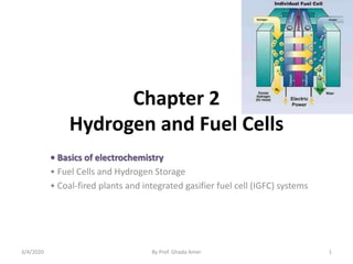
  • 1. Chapter 2 Hydrogen and Fuel Cells • Basics of electrochemistry • Fuel Cells and Hydrogen Storage • Coal-fired plants and integrated gasifier fuel cell (IGFC) systems 3/4/2020 By Prof. Ghada Amer 1
  • 2. Electrochemistry and Redox • Oxidation-reduction: “Redox” • Electrochemistry: study of the interchange between chemical change and electrical work • Electrochemical cells: systems utilizing a redox reaction to produce or use electrical energy Redox Review • Redox reactions: electron transfer processes • Oxidation: loss of 1 or more e- • Reduction: gain of 1 or more e- • Oxidation numbers: imaginary charges • (Balancing redox reactions) 3/4/2020 By Prof. Ghada Amer 2
  • 3. Oxidation Numbers (O.N.) 1. Pure element O.N. is zero 2. Monatomic ion O.N. is charge 3. Neutral compound: sum of O.N. is zero 4. Polyatomic ion: sum of O.N. is ion’s charge *Negative O.N. generally assigned to more electronegative element 5. Hydrogen assigned +1 (metal hydrides, -1) 6. Oxygen assigned -2 (peroxides, -1; OF2, +2) 7. Fluorine always -13/4/2020 By Prof. Ghada Amer 3
  • 4. Redox • Oxidation is loss of e- causes reduction “reducing agent” • Reduction is gain of e- causes oxidation “oxidizing agent” 3/4/2020 By Prof. Ghada Amer 4
  • 5. Balancing Redox Reactions 1. Write separate equations (half-reactions) for oxidation and reduction 2. For each half-reaction a. Balance elements involved in e- transfer b. Balance number e- lost and gained 3. To balance e- . multiply each half-reaction by whole numbers 4. Add half-reactions/cancel like terms (e-) 5. Acidic conditions: Balance oxygen using H2O Balance hydrogen using H+ 6. Basic conditions: Balance oxygen using OH- Balance hydrogen using H2O 7. Check that all atoms and charges balance Balancing Redox Reactions: Acidic 3/4/2020 By Prof. Ghada Amer 5
  • 6. Types of cells Voltaic (galvanic) cells: • a spontaneous reaction generates electrical energy Electrolytic cells: • absorb free energy from an electrical source to drive a nonspontaneous reaction 3/4/2020 By Prof. Ghada Amer 6
  • 7. Common Components • Electrodes: conduct electricity between cell and surroundings • Electrolyte: mixture of ions involved in reaction or carrying charge • Salt bridge: completes circuit (provides charge balance) Electrodes • Anode: • Oxidation occurs at the anode • Cathode: Reduction occurs at the cathode 3/4/2020 By Prof. Ghada Amer 7
  • 8. 17_360 Porous disk Reducing agent Oxidizing agent e – e – e – e – e – e – CathodeAnode (b)(a) Oxidation Reduction Voltaic (Galvanic) Cells 3/4/2020 By Prof. Ghada Amer 8
  • 9. 3/4/2020 By Prof. Ghada Amer 9
  • 10. 3/4/2020 By Prof. Ghada Amer 10
  • 11. 3/4/2020 By Prof. Ghada Amer 11
  • 12. Zn2+ (aq) + Cu(s)  Cu2+ (aq) + Zn(s) • Zn gives up electrons to Cu – “pushes harder” on e- – greater potential energy – greater “electrical potential” • Spontaneous reaction due to – relative difference in metals’ abilities to give e- – ability of e- to flow 3/4/2020 By Prof. Ghada Amer 12
  • 13. Cell Potential • Cell Potential / Electromotive Force (EMF): • The “pull” or driving force on electrons • Measured voltage (potential difference) V C J movedchargeofunit energypotentialelectricalorwork Ecell  3/4/2020 By Prof. Ghada Amer 13
  • 14. 17_363 e– e– e– e– Zn 2+ SO4 2– Zn(s) 1.0 M Zn 2+ solution Anode 1.0 M Cu 2+ solution Cathode Cu 2+ SO4 2– Cu(s) Ecell = +1.10 V 3/4/2020 By Prof. Ghada Amer 14
  • 15. 3/4/2020 By Prof. Ghada Amer 15
  • 16. 3/4/2020 By Prof. Ghada Amer 16
  • 17. The diagram to the right illustrates what really happens when a Galvanic cell is constructed from zinc sulfate and copper (II) sulfate using the respective metals as electrodes. 3/4/2020 By Prof. Ghada Amer 17
  • 18. Electrolysis of molten sodium chloride Electrolytic cells  None spontaneous reaction converted to spontaneous reaction  Electrical energy converted into chemical energy Conduction in Electrochemical cells: a. External connection  Movement of electrons through the external wire. b. Within the solution  migration of cations and anions c. At the electrode surface  Oxidation/Reduction reaction 3/4/2020 By Prof. Ghada Amer 18
  • 19. A simplified drawing of a membrane cell for the production of NaOH and Cl2 gas from a saturated, aqueous solution of NaCl (brine). 3/4/2020 By Prof. Ghada Amer 19
  • 20. Chapter 2 Hydrogen and Fuel Cells • Basics of electrochemistry • Fuel Cells and Hydrogen Storage • Coal-fired plants and integrated gassifier fuel cell (IGFC) systems 3/4/2020 By Prof. Ghada Amer 20
  • 21. History • Invented in the early 1840’s by Sir William Robert Grove • In 1890’s Nernst develops the first solid oxide fuel cell • Recovery of alkaline fuel cells created by General Electric for Gemini and Orbiter space programs • In the 60’s DuPont designed the membrane still used in most PEM (proton exchange membrane ) fuel cells today, Nafion • In the 80’s there was a breakthrough in the reduction of catalyst amount needed 3/4/2020 By Prof. Ghada Amer 21
  • 22. 3/4/2020 By Prof. Ghada Amer 22 Why Fuel Cells?: Naturally Cleaner No other energy technology offers the combination of benefits that fuel cells offer: • Low / Zero Emissions • High Efficiency / Low CO2 • Wide Range of Applications and Fuels • Distributed Installation • High Quality Power • Quiet • Few moving parts High Efficiency Energy efficiencies of 40%-50% or greater (85-95% with co-generation) - Energy security - Energy savings - Greenhouse gas reductions
  • 23. Types of Fuel Cells • Solid Oxide • Molten Carbonate • Proton Exchange Membrane 3/4/2020 By Prof. Ghada Amer 23
  • 24. Solid Oxide FC A fuel cell is like a battery that always runs. It consists of three parts: 1. an electrolyte, 2. an anode, and 3. a cathode. 3/4/2020 By Prof. Ghada Amer 24 • For a solid oxide fuel cell, the electrolyte is a solid ceramic material. • The anode and cathode are made from special inks that coat the electrolyte. • Unlike other types of fuel cells, no precious metals, corrosive acids, or molten materials are required. • In this cell, an electrochemical reaction converts fuel and air into electricity without combustion.
  • 25.  (SOFC) use a hard, ceramic compound of metal (like calcium or zirconium) oxides (chemically, O2) as electrolyte  Operating temperatures of 800-1,000 °C (about 1,800 °F).  As long as there's fuel, air, and heat, the process continues producing clean, reliable, affordable energy.  Operates at 45-60% efficiency, 85% with cogeneration  Mainly used for industrial applications, may be used in automobiles as an auxiliary power unit  Power output of 100 kW 3/4/2020 By Prof. Ghada Amer 25
  • 26. Operating Principle 1. A solid oxide fuel cell is a high temperature fuel cell. At high temperature, warmed air enters the cathode side of the fuel cell and steam mixes with fuel to produce reformed fuel… which enters on the anode side. 2. The chemical reaction begins in the fuel cell. As the reformed fuel crosses the anode, it attracts oxygen ions from the cathode. 3/4/2020 By Prof. Ghada Amer 26
  • 27. 3. The oxygen ions combine with the reformed fuel to produce electricity, water, and small amounts of carbon dioxide. 4. The water gets recycled to produce the steam needed to reform the fuel. 5. The process also generates the heat required by the fuel cell. 3/4/2020 By Prof. Ghada Amer 27
  • 28. • A fuel gas containing hydrogen, such as methane, flows past the anode. Negatively charged oxygen ions migrate through the electrolyte membrane react with the hydrogen to form water, • The reacts with the methane fuel to form hydrogen (H2) & carbon dioxide (CO2). 3/4/2020 By Prof. Ghada Amer 28
  • 29.  This electrochemical reaction generates electrons, which flow from the anode to an external load and back to the cathode, a final step that both completes the circuit and supplies electric power.  To increase voltage output, several fuel cells are stacked together to form the heart of a clean power generator. 3/4/2020 By Prof. Ghada Amer 29
  • 30. 3/4/2020 By Prof. Ghada Amer 30
  • 31. SOFC Design types • According to the type of cell configuration and developer, Three major configurations for stacking the cells together to increase the voltage and power are: 1. Tubular (as developed by Westinghouse and Mitsubishi Heavy Industries), –The tubular design (Westinghouse design) is by far the most advanced SOFC concept with 40 kW prototypes operating. –Tubes up to 1 m in length represent single cells and stacks are formed by stacking the tubes together. 3/4/2020 By Prof. Ghada Amer 31 - The concept is a supported cell design where thin adherent layers are deposited on tubular supports by costly fabrication methods such as electrochemical vapor deposition (EVD) or low pressure plasma deposition.
  • 32. 3/4/2020 By Prof. Ghada Amer 32
  • 33. 2. Flat plate (as developed by Ceramatec and Mitsubishi Heavy Industries), - The planar or flat plate design is the most common concept under development as its fabrication is potentially least costly. - Single cells can be produced by conventional ceramic mass production routes such as tape casting and screen printing. - The single cells are stacked together and sealed with a high temperature sealing material. - Numerous variations of the concept, including external and internal co- flow, counter-flow and cross-flow manifold stacks are under development. 3/4/2020 By Prof. Ghada Amer 33
  • 34. 3. Monolithic (as developed by Allied Signal). - In the monolithic design green coats of air electrode/electrolyte/fuel electrode and interconnect are formed and co-sintered. - This eliminates the need for high temperature seals, but requires forming the stack by co-sintering, a rather difficult task considering the different materials involved and microstructure requirements for each layer.  Hybrid designs between monolithic and planar are also under development. 3/4/2020 By Prof. Ghada Amer 34
  • 35. 3/4/2020 By Prof. Ghada Amer 35
  • 36. 3/4/2020 By Prof. Ghada Amer 36 Applications • Suitable for decentralized electricity production • While the major application of SOFCs are seen in stationary plants, auxiliary power units in • Transportation vehicles • On-board power for aircraft • Power packs- small enough to be carried by soldiers, has been motivated by DARPA (Defense Advanced Research Projects Agency)
  • 37. Drawbacks • The high temperature limits applications of SOFC units and they tend to be rather large • While solid electrolytes cannot leak, they can crack. • Complex materials • Assembling • Maintenance • Design Cost & choice of material 3/4/2020 By Prof. Ghada Amer 37
  • 38. Molten Carbonate Fuel Cells - MCFC • They evolved from work in the 1960's aimed at producing fuel cell which would operated directly on coal. • The operation on coal-derived fuel gases or natural gas is viable. • Molten carbonate fuel cells (MCFCs) use a molten carbonate salt suspended in a porous ceramic matrix as the electrolyte. • Salts commonly used include lithium carbonate, potassium carbonate and sodium carbonate. • Operating temperature of 650oC • Operates at 40-60%, 85% with cogeneration • Produces water and carbon dioxide 3/4/2020 By Prof. Ghada Amer 38
  • 39. 3/4/2020 By Prof. Ghada Amer 39 Operating Principle • The anode process involves a reaction between hydrogen and carbonate ions (CO3 =) from the electrolyte. The reaction produces water and carbon dioxide (CO2) while releasing electrons to the anode. • The cathode process combines oxygen and CO2 from the oxidant stream with electrons from the cathode to produce carbonate ions which enter the electrolyte. • The need for CO2 in the oxidant stream requires a system for collecting CO2 from the anode exhaust and mixing it with the cathode feed stream. Before this can be done, any residual hydrogen in the spent fuel stream must be burned
  • 40. Reactions in MCFC • The anode process involves a reaction between hydrogen and carbonate ions (CO3 =) from the electrolyte.  The reaction produces water and carbon dioxide (CO2) while releasing electrons to the anode.  The cathode process combines oxygen and CO2 from the oxidant stream with electrons from the cathode to produce carbonate ions which enter the electrolyte.  The need for CO2 in the oxidant stream requires a system for collecting CO2 from the anode exhaust and mixing it with the cathode feed stream. 3/4/2020 By Prof. Ghada Amer 40
  • 41. Reactions in MCFC 3/4/2020 By Prof. Ghada Amer 41
  • 42. 3/4/2020 By Prof. Ghada Amer 42
  • 43. • As the operating temperature increases,  the theoretical operating voltage for a fuel cell decreases and with it the maximum theoretical fuel efficiency.  On the other hand, increasing the operating temperature increases the rate of the electrochemical reaction and thus increases the current which can be obtained at a given voltage. • The MCFC also produces excess heat at a temperature which is high enough to yield high pressure steam which may be fed to a turbine to generate additional electricity. (the high operating temperature of the MCFC offers the possibility that it could operate directly on gaseous hydrocarbon fuels such as natural gas) 3/4/2020 By Prof. Ghada Amer 43
  • 44. • Future systems may incorporate membrane separators to remove the hydrogen for recirculation back to the fuel stream. • Significant technology has been developed to provide electrode structures which position the electrolyte with respect to the electrodes and maintain that position while allowing for some electrolyte boil-off during operation. • The electrolyte boil-off has an insignificant impact on cell stack life. • A more significant factor of life expectation has to do with corrosion of the cathode. 3/4/2020 By Prof. Ghada Amer 44
  • 45. 3/4/2020 By Prof. Ghada Amer 45 They operate at high temperature, around 650ºC and there are several advantages associated with this. 1. Firstly, the high operating temperature dramatically improves reaction kinetics and thus it is not necessary to boost these with a noble metal catalyst. 2. The higher temperature also makes the cell less prone to carbon monoxide poisoning than lower temperature systems. 3. As a result, MCFC systems can operate on a variety of different fuels, including coal-derived fuel gas, methane or natural gas, eliminating the need for external reformers.
  • 46. 3/4/2020 By Prof. Ghada Amer 46 Applications  MCFCs are used in large stationary power generation. typically 250kW to 3MW  Most fuel cell power plants of megawatt capacity use MCFCs, as do large combined heat and power (CHP) and combined cooling and power (CCP) plants.  These fuel cells can work at up to 60% efficiency for fuel to electricity conversion, and overall efficiencies can be over 80% in CHP or CCP applications where the process heat is also utilized.  In powering large telecommunications facilities  Primary application is stationary power plants a. Electrical Utilities b. Industrial and distributed power generation c. Military and Government (Post Office)  Future application may include ship power plants a. Navy and civilian shipping
  • 47. Drawbacks 1. arise from using a liquid electrolyte rather than a solid and the requirement to inject carbon dioxide at the cathode as carbonate ions are consumed in reactions occurring at the anode. 2. There have also been some issues with high temperature corrosion and the corrosive nature of the electrolyte but these can now be controlled to achieve a practical lifetime. 3. The main problem with MCFC is the slow dissolution of the cathode in the electrolyte. Most of the research is therefore in the area of more durable materials and cathodes 3/4/2020 By Prof. Ghada Amer 47
  • 48. Proton Exchange Membrane FC • Utilizes a polymer membrane as the electrolyte (poly-perflourosulfonic acid, Nafion) • Operate at much lower temperatures, ~80oC • Operates a 35-60%, 85% cogeneration • Produces water • Mainly used in mobile applications • Power output of 50-250 kW 3/4/2020 By Prof. Ghada Amer 48
  • 49. Four Basic Elements in a PEMFC • Anode: the negative post of the fuel cell, has several jobs. It conducts the electrons that are freed from the hydrogen molecules, so that they can be used in an external circuit. It has channels etched into it that disperse the hydrogen gas equally over the surface of the catalyst. • Cathode: the positive post of the fuel cell, has channels etched into it that distribute the oxygen to the surface of the catalyst. It also conducts the electrons back from the external circuit to the catalyst, where they can recombine with the hydrogen ions and oxygen to form water. 3/4/2020 By Prof. Ghada Amer 49
  • 50. • The electrolyte is the proton exchange membrane. This specially treated material, which looks something like ordinary kitchen plastic wrap, only conducts positively charged ions. The membrane blocks electrons. • The catalyst is a special material that facilitates the reaction of oxygen and hydrogen. It is usually made of platinum powder very thinly coated onto carbon paper or cloth. The catalyst is rough and permeable so that the maximum surface area of the platinum can be exposed to the hydrogen or oxygen. The platinum-coated side of the catalyst faces the PEM. 3/4/2020 By Prof. Ghada Amer 50
  • 51. PEM FC Design Components • Membrane/Electrode Assembly • Gas Diffusion Layer • Bipolar plates http://www.fuelcellcomponents.com DuPont Conductive Plates, http://www.dupont.com/fuelcells/products/plates.html3/4/2020 By Prof. Ghada Amer 51
  • 52. PEM FC Design • Membrane should have high proton conductivity and low water permeability • Electrodes function best when made of noble metal catalysts • Optimal channel geometry for cathode side of bipolar plating – Minimizing width between channels – Decreasing channel cross-section – Increasing channel depth 3/4/2020 By Prof. Ghada Amer 52
  • 53. PEM FC Design (Cont.) • Water Management – Drying leads to decreased performance of the cell from decreased conductance – Saturation with water causes degradation of fuel cell materials, decreases mass transfer • Heat Management – Increasing the temperature is often used to vaporize water and increase mass transport – The waste heat from PEM’s is of limited usage because of little temperature difference 3/4/2020 By Prof. Ghada Amer 53
  • 54. PEMFC: Proton Exchange Membrane Fuel Cell The cell uses one of the simplest reactions of any fuel cell. 3/4/2020 By Prof. Ghada Amer 54
  • 55. Operation of PEM FC http://www.fueleconomy.gov/feg/fcv_PEM.shtml3/4/2020 By Prof. Ghada Amer 55
  • 56. 3/4/2020 By Prof. Ghada Amer 56 Applications • In 1995,Ballard systems tested PEM cells in buses in Chicago and later in experimental vehicles made by Daimler Chrysler • In 2000,AeroVironments selected PEM technology to provide night time power for its solar powered Helios long duration aircraft • Basically, fuel cells have been investigated as an innovative system that can be integrated transportation, stationary and portable applications • US and Japan have concentrated on the application field of FC cars, and the EU has directed their attention to the FC buses and trains. • there have been RPG applications in Japan and the FC bicycle or lightweight FC car in China. Table 2 shows the advantages and disadvantages of PEMFC in each application as well as the results of the application tests carried out in the world since 2002.
  • 57. 3/4/2020 By Prof. Ghada Amer 57
  • 58. 3/4/2020 By Prof. Ghada Amer 58 Type of fuel cell Applications Core temp. efficiency Advantages Limitations Proton Exchange Membrane (PEMFC) Portable, stationary and automotive 50–100°C; 80°C typical; 35–60% efficient Compact design, long operating life, quick start-up, well developed Expensive catalyst; needs chemical grade fuel; complex heat and water control Alkaline (AFC) Space, military, submarines, transport 90–100°C; 60% efficient Low parts and, operation costs; no compressor; fast cathode kinetics Large size; sensitive to hydrogen and oxygen impurities Molten Carbonate (MCFC) Large power generation 600–700°C; 45–50% efficient High efficiency, flexible to fuel, co-generation High heat causes corrosion, long startup, short life Phosphoric Acid (PAFC) Medium to large power generation 150–200°C; 40% efficient Good tolerance to fuel impurities; co-generation Low efficiency; limited service life; expensive catalyst Solid Oxide (SOFC) Medium to large power generation 700–1000°C; 60% efficient Lenient to fuels; can use natural gas, high efficient High heat causes corrosion, long startup, short life Direct Methanol (DMFC) Portable, mobile and stationary use 40–60°C; 20% efficient Compact; feeds on methanol; no compressor Complex stack; slow response; low efficiency
  • 59. Fuel Cells in the Automotive Industry • Comparing: – Availability/Cost – Power density – Lifetime – Fuel sources • Hydrogen storage www.lynntech.com/.../ pem_fuelcell/index.shtml 3/4/2020 By Prof. Ghada Amer 59
  • 60. Hydrogen storage 3/4/2020 By Prof. Ghada Amer 60 Hydrogen derived from:
  • 61. Hydrogen Production 3/4/2020 By Prof. Ghada Amer 61
  • 62. 3/4/2020 By Prof. Ghada Amer 62 • Hydrogen storage is a key enabling technology for the advancement of hydrogen and fuel cell technologies that can provide energy for an array of applications, including stationary power, portable power, and transportation. • Also, hydrogen can be used as a medium to store energy created by intermittent renewable power sources (e.g., wind and solar) during periods of high availability and low demand, increasing the utilization and benefits of the large capital investments in these installations. • The stored hydrogen can be used during peak hours, as system backup, or for portable, transportation, or industrial applications. • The U.S. Department of Energy’s (DOE’s) efforts through 2011 have primarily been focused on the Research, Development, and Demonstration (RD&D) of onboard vehicular hydrogen storage systems that will allow for a driving range of 300 miles or more, while meeting packaging, cost, safety, and performance requirements to be competitive with conventional vehicles.
  • 63. • As of 2011, there were over 180 fuel cell light-duty vehicles and over 20 fuel cell buses utilizing compressed hydrogen storage. • In the DOE’s Technology Validation sub-program National Fuel Cell Electric Vehicle (FCEV) Learning Demonstration project, automakers have validated vehicles with more than a 250-mile driving range. • Additionally, at least one vehicle has been demonstrated capable of 430 miles on a single fill of hydrogen; however the driving range must be achievable across the range of light-duty vehicle platforms and without compromising space, performance or cost. • There is a host of early or near-term power applications in which fuel cell technologies are expected to achieve wide-scale commercialization prior to light-duty vehicles. 3/4/2020 By Prof. Ghada Amer 63
  • 64. 3/4/2020 By Prof. Ghada Amer 64 • The early market applications can generally be categorized into three market segments:  stationary power such as backup power for telecommunications towers, emergency services, and basic infrastructure (e.g., water and sewage pumps).  portable power such as personal laptop battery rechargers, portable generator sets (gen-sets), or mobile lighting.  material handling equipment such as forklift trucks, pallet jacks, and airport baggage and pushback tractors.
  • 65. Hydrogen Storage –It’s More Than a Tank Hydrogen storage systems on H2vehicles must: •Contain •Control •Regulate •Monitor •Distribute •Meter •Refill •Survive 3/4/2020 By Prof. Ghada Amer 65
  • 66. 3/4/2020 By Prof. Ghada Amer 66
  • 67. Hydrogen Storage Types • Metal hydrides • Pressurized hydrogen gas • Liquefied hydrogen 3/4/2020 By Prof. Ghada Amer 67
  • 68. Metal Hydrides • Metal hydrides (MHx) are the most technologically relevant class of hydrogen storage materials because they can be used in a range of applications including: 1. neutron moderation, 2. electrochemical cycling, 3. thermal storage, 4. heat pumps, and 5. purification/separation. Metal hydrides, such as those utilized in laptop computer nickel- metal hydride batteries, are filled with metal powders that absorb and release hydrogen. This is the safest method known for storing flammable hydrogen gas. 3/4/2020 By Prof. Ghada Amer 68
  • 69. 3/4/2020 By Prof. Ghada Amer 69
  • 70. Pressurized Hydrogen Gas • Compressed Gaseous Hydrogen (GH2)- Vehicular compressed hydrogen systems consisting of 34.5 MPa (5,000 psi) gaseous hydrogen in metal or plastic lined, carbon fiber wound pressure vessels. This offer :  simplicity of design and use,  rapid refueling capability,  excellent dormancy characteristics,  minimal infrastructure impact,  high safety due to the inherent strength of the pressure vessel, and  little to no development risk. The disadvantages are • ‘system volume and use of high pressure. • Integrating the moderate-to-large system volume will clearly challenge the automotive designer, but such a tank volume can be packaged into a “clean sheet” vehicle. BUT the many advantageous features of compressed gas storage outweigh its larger volume. 3/4/2020 By Prof. Ghada Amer 70
  • 71. Liquefied Hydrogen • Liquid Hydrogen (H2) typically has to be stored at -423°F (-253°C or 20 K). • The temperature requirements for liquid hydrogen storage necessitate expending a great deal of energy to compress and chill the hydrogen into its liquid state. • The cooling and compressing process requires energy, resulting in a net loss of about 30% of the energy that the liquid hydrogen is storing. • The storage tanks are insulated to maintain temperature. • Liquid Hydrogen is often stored at higher pressure so significant reinforcement is used. • The margin of safety concerning liquid hydrogen storage is a function of maintaining tank integrity and preserving the temperatures that liquid hydrogen requires. • Combine the cost or energy required for the process to get hydrogen into its liquid state and the cost of tanks required to sustain the storage pressure and temperature, and liquid hydrogen storage becomes very expensive compared to other methods. 3/4/2020 By Prof. Ghada Amer 71
  • 72. 3/4/2020 By Prof. Ghada Amer 72
  • 73. Hydrogen Safety Performance-Based Safety Standards Will Ensure Safe Hydrogen Storage and Handling 3/4/2020 By Prof. Ghada Amer 73  Current designs are based on decades of industrial experience with compressed gases and hydrogen  Government and industry groups are developing standards  Hydrogen has been produced and transported in the U.S. >50 years  Hydrogen gas diffuses rapidly  Ford Motor Co. released a report in 1997 examining safety of hydrogen use in vehicles
  • 74. Hydrogen vs. Gasoline 3/4/2020 74By Prof. Ghada Amer
  • 75. Making the Hydrogen Economy a Reality Automakers need –Hydrogen storage solution –Assurances that refueling infrastructure will be there Suppliers need –Production volume to reduce costs through economies of scale –Demand sufficient to justify capital expenditures –Consistent, performance-based codes and standards Consumers need –Vehicles that are transparent to own and operate –Convenient refueling and cost-competitive fuel 3/4/2020 By Prof. Ghada Amer 75
  • 76. In the news… • Aug. 10, 2004 – Ford produces 30 Ford Focus Fuel Cell Vehicles to be tested in real world • Oct. 25, 2004 - GM designing hydrogen powered HUMMER H2 • Jan 25, 2005 – GM and Shell team up to begin production of fuel cell feel for New York 3/4/2020 By Prof. Ghada Amer 76
  • 77. Chapter 2 Hydrogen and Fuel Cells • Basics of electrochemistry • Fuel Cells and Hydrogen Storage • Coal-fired plants and integrated gassifier fuel cell (IGFC) systems 3/4/2020 By Prof. Ghada Amer 77
  • 78. Integrated Coal Gasification Combined Cycle (IGCC) Power Plants 3/4/2020 By Prof. Ghada Amer 78 IGCC: What is it? “Integrated coal Gasification Combined Cycle” or IGCC Chemical conversion of coal to synthetic gas for combustion in a modified gas turbine Inherently cleaner process because coal is not combusted and the relatively small volumes of syngas are easier to clean up than the much larger volumes of flue gases at a coal combustion plant.
  • 79. • The need of clean energy technologies has been in existence since the first oil crisis more than 25 years ago. • IGCC is emerging today as one of the most promising technologies to exploit low-quality solid and liquid fuels and meet the most stringent emission limits. • Integrated Gasification Combined Cycle (IGCC) is emerging as a best available technology to utilize low quality or contaminated energy resources, coal or oil. • In particular IGCC offers refiners the possibility of reducing to zero the production of residual fuel oil, an increasingly undesired product, while at the same time, co-producing electricity, hydrogen and steam. • It also drastically cuts SO2 emissions. 3/4/2020 By Prof. Ghada Amer 79
  • 80. How does IGCC work? IGCC is a combination of two leading technologies.  The first technology is called coal gasification, which uses coal to create a clean-burning gas (syngas). • The second technology is called combined-cycle, which is the most efficient method of producing electricity commercially available today. Coal Gasification: • The gasification portion of the IGCC plant produces a clean coal gas (syngas) which fuels the combustion turbine. • Coal is combined with oxygen in the gasifier to produce the gaseous fuel, mainly hydrogen and carbon monoxide. • The gas is then cleaned by a gas cleanup process. • After cleaning, the coal gas is used in the combustion turbine to produce electricity. 3/4/2020 By Prof. Ghada Amer 80
  • 81. Classification of Gasifiers • Gasification systems can incorporate any one of a number of gasifiers. Six gasification technologies that are predominantly used in commercial applications and/or have been extensively studied are: • Entrained Flow (Downflow) Gasifier • E-GAS Entrained Flow (Upflow) Gasifier • Shell Entrained Flow (Upflow) Gasifier • Fluidized-Bed Gasifier • Transport Reactor Gasifier • Lurgi Dry Ash Gasifier • British Gas/Lurgi Fixed-Bed Gasifier • Future Energy Entrained Flow Gasifier • Prenflo Entrained Bed Gasifier 3/4/2020 By Prof. Ghada Amer 81
  • 82. Integration Between Air Separation and Gas Turbine Integration means recovery of the waste energy available, improvement of the efficiency and, where possible, reduction of the investment cost. • There are potential benefits of integrating two major components of the IGCC: the gas turbine and the air separation plant. • There are several possible degrees of integration between the air separation plant and the gas turbine. • In the case of total integration, 100% of the air required by the air separation is supplied by bleeding some of the air from the discharge of the gas turbine compressor. • Oxygen is recompressed and used in gasification, while nitrogen is recompressed and reinjected in the syngas to refill the mass deficit caused by the air bleeding, and, at the same time, reduce N0x formation during combustion by lowering the flame peak temperature. 3/4/2020 By Prof. Ghada Amer 82
  • 83. Basic Structure of IGCC Air N2 3/4/2020 By Prof. Ghada Amer 83
  • 84. Steam Hydrogen Ammonia F-T Liquids Clean Syngas End ProductsFeeds Gas Cleanup Refinery Residues Heavy Oil Orimulsion Coal Petroleum Coke Oxygen Electricity Solid Sulfur Slag (ash) Gas & Steam Turbines Gasification Combined Cycle Power Block SULFUR RECOVERY Marketable Byproducts: Alternatives: Alternatives: SULFUR REMOVAL Coal IGCC Process1 1 Texaco Gasification Power Systems (TGPS) Natural Gas 3/4/2020 By Prof. Ghada Amer 84
  • 85. c 3/4/2020 By Prof. Ghada Amer 85
  • 86. 3/4/2020 By Prof. Ghada Amer 86
  • 87. IGCC Environmental Impacts - Air Pollution • Commercially available IGCC power plant technologies can have much lower air pollution emissions than new conventional coal plants. • Commercially available IGCC power plant technologies produce substantially smaller volumes (about one half) of solid wastes than do new conventional coal plants using the same coal • IGCC solid wastes are less likely to cause environmental damage than fly ash from conventional coal plants because IGCC ash melts in the gasification process, resulting in an ash much less subject to leaching pollutants than is conventional coal combustion fly ash. 3/4/2020 By Prof. Ghada Amer 87
  • 88. IGCC Carbon Emissions • IGCC plants are more efficient in converting coal to electricity than conventional coal plants and thus produce less CO2 per unit of electricity generated. – Near-term IGCC plants would produce about 20% less CO2 - per unit of electricity produced - as would the “average” existing coal plant. • The longer term potential could be for IGCC plants to produce about one-third less CO2 - per unit of electricity produced - as would the “average” existing coal plant. • IGCC plants can potentially capture and geologically sequester up to 90% (or more) of coal fuel carbon content. 3/4/2020 By Prof. Ghada Amer 88
  • 89. Comparative SO2 Emissions 1.85 0.16 0.00 0.00 0.20 0.40 0.60 0.80 1.00 1.20 1.40 1.60 1.80 2.00 New Coal Current IGCC New Natural gas EmissionsinPoundsperMWH 3/4/2020 By Prof. Ghada Amer 89
  • 90. Comparative NOx Emissions 1.11 0.16 0.07 0.000 0.200 0.400 0.600 0.800 1.000 1.200 New Coal Current IGCC New Natural gas EmissionsinPoundsperMWH 3/4/2020 By Prof. Ghada Amer 90
  • 91. A Bridge to Hydrogen Fuels • Movement of IGCC technology into the power market could facilitate use of coal to produce valuable products beyond electricity - – FT diesel fuel – Chemical feed stocks – Synthestic natural gas – Hydrogen, or hydrogen-rich liquid fuels for transportation and building energy • Hydrogen is the ultimate fuel cell fuel (current fuels cells often include equipment to convert other fuels - natural gas, etc. - to hydrogen). • IGCC is seen by key experts as being critical to economic deployment of hydrogen transportation fuels and widespread use of fuel cells. • Successful deployment of IGCC technology in the power sector may be critical to the economic viability of other potential coal-derived products. 3/4/2020 By Prof. Ghada Amer 91
  • 92. The Optimization of IGCC • Technology Selection • Process Simplification • Classes of Plant Quality • Process Reliability Modeling • Design-to-Capacity • Predictive Maintenance • Traditional Value Engineering • Constructability and Schedule Optimization 3/4/2020 By Prof. Ghada Amer 92
  • 93. Question time !!! Now I need the 1thstudent (from left) in second row, with the 1thstudent (from left) in last row 3/4/2020 By Prof. Ghada Amer 93