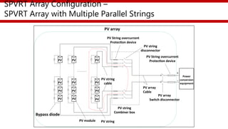
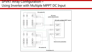
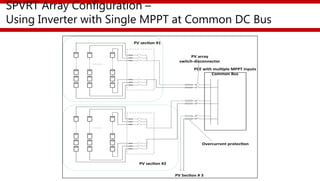
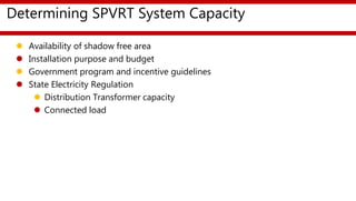
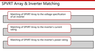
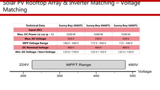
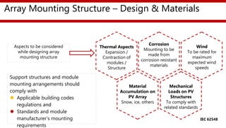
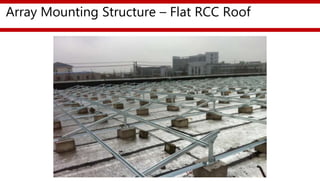
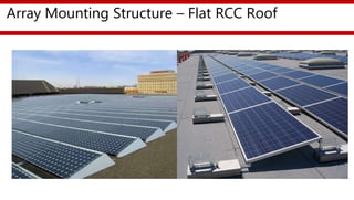
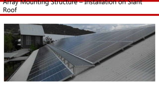
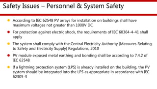
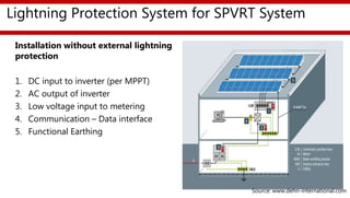
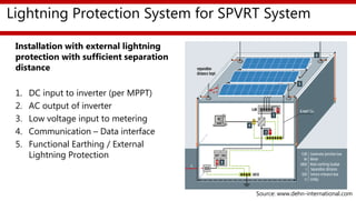
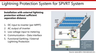
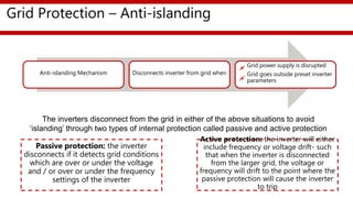
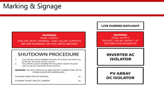
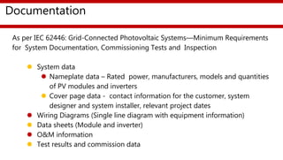
Partnership To Advance Clean Energy-Deployment (PACE-D)
Technical Assistance Program
Presented by
USAID PACE-D TA Program
Apr-18
Solar PV Rooftop Training Program For Entrepreneurs
Session:
SPVRT System Design & Safety Overview
Contents
SPVRT Array Configuration
Determining SPVRT Array Capacity
SPVRT Array – Inverter Matching
Array Mounting Structure – Materials & Design
Contents
Safety Issues – Personal & System Safety
Grid Protection – Anti Islanding
Selection of SPVRT Array and Array BOS Components
Installation Best Practices
SPVRT Array Configuration –
SPVRT Array with Multiple Parallel Strings
SPVRT Array Configuration –
Using Inverter with Multiple MPPT DC Input
SPVRT Array Configuration –
Using Inverter with Single MPPT at Common DC Bus
SPVRT Array Configuration –
Single MPPTs Vs. Multiple MPPT Input
 According to IEC 62548 Photovoltaic array design requirement, when inverters
have multiple MPPT inputs, overcurrent protection of the section of the array
may be treated as a separate PV array and each PV array shall have a switch
disconnector to provide isolation of the inverter
 Where inverter has a single MPPT and multiple input circuits are internally
paralleled onto a common DC bus, each PV section connected to one of those
inputs shall be treated as a sub-array and each PV sub-array shall have a switch
disconnector to provide isolation of the inverter.
Determining SPVRT System Capacity
 Availability of shadow free area
 Installation purpose and budget
 Government program and incentive guidelines
 State Electricity Regulation
 Distribution Transformer capacity
 Connected load
SPVRT Array & Inverter Matching
Matching of SPVRT Array to the voltage specification
of an inverter
Matching of SPVRT Array to the inverter’s current
rating
Matching of SPVRT Array to the inverter’s power rating
Solar PV Rooftop Array & Inverter Matching – Voltage
Matching
Array Mounting Structure – Design & Materials
Thermal Aspects
Expansion /
Contraction of
modules /
Structure
Mechanical
Loads on PV
Structures
To comply with
related standards
Wind
To be rated for
maximum
expected wind
speeds
Material
Accumulation on
PV Array
Snow, ice, others
Corrosion
Mounting to be
made from
corrosion resistant
materials
Support structures and module
mounting arrangements should
comply with
 Applicable building codes
regulations and
 Standards and module
manufacturer’s mounting
requirements
Aspects to be considered
while designing array
mounting structure
IEC 62548
Array Mounting Structure – Flat RCC Roof
Array Mounting Structure – Installation on Slant
Roof
Array Mounting Structure – Installation on Slant
Roof
Safety Issues – Personnel & System Safety
 According to IEC 62548 PV arrays for installation on buildings shall have
maximum voltages not greater than 1000V DC
 For protection against electric shock, the requirements of IEC 60364-4-41 shall
apply
 The system shall comply with the Central Electricity Authority (Measures Relating
to Safety and Electricity Supply) Regulations, 2010
 PV module exposed metal earthing and bonding shall be according to 7.4.2 of
IEC 62548
 If a lightning protection system (LPS) is already installed on the building, the PV
system should be integrated into the LPS as appropriate in accordance with IEC
62305-3
SPVRT Array Functional Earthing/Bonding Decision
Tree
Entry
Is the
PV array
maximum voltage
>DVC-A?
Is array
exposed-conductive part
required to be earthed for
lightning protection?
(a)
Is array
exposed-conductive part
required to be earthed for
lightning protection?
(a)
Earth
with conductor sized
according to 7.4.2.1 and
IEC 60364-5-54
Maximum size 6mm2
Earth
with conductor sized
according to 7.4.2.1 and
IEC 60364-5-54
Maximum size 16mm2
NO
YES
NO
YES
No
requirement
NO
YES
IEC 62548
Lightning Protection System for SPVRT System
Installation without external lightning
protection
1. DC input to inverter (per MPPT)
2. AC output of inverter
3. Low voltage input to metering
4. Communication – Data interface
5. Functional Earthing
Source: www.dehn-international.com
Lightning Protection System for SPVRT System
Installation with external lightning
protection with sufficient separation
distance
1. DC input to inverter (per MPPT)
2. AC output of inverter
3. Low voltage input to metering
4. Communication – Data interface
5. Functional Earthing / External
Lightning Protection
Source: www.dehn-international.com
Lightning Protection System for SPVRT System
Installation with external lightning
protection without sufficient
separation distance
1. DC input to inverter (per MPPT)
2. AC output of inverter
3. Low voltage input to metering
4. Communication – Data interface
5. Functional Earthing / External
Lightning Protection
Source: www.dehn-international.com
Grid Protection – Anti-islanding
Anti-islanding Mechanism Disconnects inverter from grid when
Grid power supply is disrupted
Grid goes outside preset inverter
parameters
Passive protection: the inverter
disconnects if it detects grid conditions
which are over or under the voltage
and / or over or under the frequency
settings of the inverter
Active protection: the inverter will either
include frequency or voltage drift- such
that when the inverter is disconnected
from the larger grid, the voltage or
frequency will drift to the point where the
passive protection will cause the inverter
to trip
The inverters disconnect from the grid in either of the above situations to avoid
‘islanding’ through two types of internal protection called passive and active protection
Grid Protection – Anti Islanding
 According to IEEE 1547 and CEA (technical standards for connectivity of the
distributed generation resources) Regulation 2013 - for an unintentional island
the grid tied inverter shall detect the island and cease to energize within two
seconds of the formation of an island
 According to IEEE 1547 the grid connected rooftop soar system shall include an
adjustable delay (or a fixed delay of 5 minutes) that may delay reconnection for
up to five minutes after the grid voltage and frequency restored. As per CEA
Regulation 2013 it shall be for at least 60 seconds
 In case another power generation source like DG set in the consumer facility is
operated when grid is not available, the inverter may sense the grid availability
and in case operation parameters are within the working range it will start
functioning and will start feeding to the DG grid; depends on regulation if
allowed or not
Installation of Isolators
PV Array DC Isolator:
 A double-pole, load-breaking, DC rated isolating (disconnect) switch should be
installed on the DC side of the inverter
 It should be rated appropriately for the voltage and current of the PV system
Inverter AC Isolator:
 Central Electricity Authority (Technical Standards for Connectivity of the Distributed
Generation Resources) Regulations, 2013 requires an inverter AC isolator to be
installed on the output of the inverter
 A Main Switch lockable in off position is required to be installed in the switchboard,
which is located at a height of at-least 2.44m above the ground level
 This allows the PV system to be disconnected from the mains power supply. This
main switch may not be rated for load break nor may have feature of overcurrent
protection
Lidded Cable Tray
Labelled Every 2m
Virtually No
Exposed Conduit
Roof penetrations under solar module
Using fit for purpose equipment
Using black UV rated corrugated
Using SS Cable Ties
Appropriately Labelled
Source: www.gses.in
Cable Management at Array
 Wiring must complied with IEC 60364 or equivalent national standard
 Minimize the area of conductive loops to reduce the magnitude of lightening-
induced overvoltage
Cabling & Interconnection
Marking and signage
Marking & Signage
Documentation
Documentation
As per IEC 62446: Grid-Connected Photovoltaic Systems—Minimum Requirements
for System Documentation, Commissioning Tests and Inspection
 System data
 Nameplate data – Rated power, manufacturers, models and quantities
of PV modules and inverters
 Cover page data - contact information for the customer, system
designer and system installer, relevant project dates
 Wiring Diagrams (Single line diagram with equipment information)
 Data sheets (Module and inverter)
 O&M information
 Test results and commission data
28
Anurag Mishra
Senior Clean Energy Specialist
USAID/India
Email: amishra@usaid.gov
Disclaimer:
This training material is made possible by the support of the American
People through the United States Agency for International
Development (USAID). The contents of this material are the sole
responsibility of Nexant, Inc. and do not necessarily reflect the views of
USAID or the United States Government. This material was prepared
under Contract Number AID-386-C-12-00001.

Session 08 design & safety overview

  • 1.
    Partnership To AdvanceClean Energy-Deployment (PACE-D) Technical Assistance Program Presented by USAID PACE-D TA Program Apr-18 Solar PV Rooftop Training Program For Entrepreneurs Session: SPVRT System Design & Safety Overview
  • 2.
    Contents SPVRT Array Configuration DeterminingSPVRT Array Capacity SPVRT Array – Inverter Matching Array Mounting Structure – Materials & Design
  • 3.
    Contents Safety Issues –Personal & System Safety Grid Protection – Anti Islanding Selection of SPVRT Array and Array BOS Components Installation Best Practices
  • 4.
    SPVRT Array Configuration– SPVRT Array with Multiple Parallel Strings
  • 5.
    SPVRT Array Configuration– Using Inverter with Multiple MPPT DC Input
  • 6.
    SPVRT Array Configuration– Using Inverter with Single MPPT at Common DC Bus
  • 7.
    SPVRT Array Configuration– Single MPPTs Vs. Multiple MPPT Input  According to IEC 62548 Photovoltaic array design requirement, when inverters have multiple MPPT inputs, overcurrent protection of the section of the array may be treated as a separate PV array and each PV array shall have a switch disconnector to provide isolation of the inverter  Where inverter has a single MPPT and multiple input circuits are internally paralleled onto a common DC bus, each PV section connected to one of those inputs shall be treated as a sub-array and each PV sub-array shall have a switch disconnector to provide isolation of the inverter.
  • 8.
    Determining SPVRT SystemCapacity  Availability of shadow free area  Installation purpose and budget  Government program and incentive guidelines  State Electricity Regulation  Distribution Transformer capacity  Connected load
  • 9.
    SPVRT Array &Inverter Matching Matching of SPVRT Array to the voltage specification of an inverter Matching of SPVRT Array to the inverter’s current rating Matching of SPVRT Array to the inverter’s power rating
  • 10.
    Solar PV RooftopArray & Inverter Matching – Voltage Matching
  • 11.
    Array Mounting Structure– Design & Materials Thermal Aspects Expansion / Contraction of modules / Structure Mechanical Loads on PV Structures To comply with related standards Wind To be rated for maximum expected wind speeds Material Accumulation on PV Array Snow, ice, others Corrosion Mounting to be made from corrosion resistant materials Support structures and module mounting arrangements should comply with  Applicable building codes regulations and  Standards and module manufacturer’s mounting requirements Aspects to be considered while designing array mounting structure IEC 62548
  • 12.
    Array Mounting Structure– Flat RCC Roof
  • 13.
    Array Mounting Structure– Flat RCC Roof
  • 14.
    Array Mounting Structure– Installation on Slant Roof
  • 15.
    Array Mounting Structure– Installation on Slant Roof
  • 16.
    Safety Issues –Personnel & System Safety  According to IEC 62548 PV arrays for installation on buildings shall have maximum voltages not greater than 1000V DC  For protection against electric shock, the requirements of IEC 60364-4-41 shall apply  The system shall comply with the Central Electricity Authority (Measures Relating to Safety and Electricity Supply) Regulations, 2010  PV module exposed metal earthing and bonding shall be according to 7.4.2 of IEC 62548  If a lightning protection system (LPS) is already installed on the building, the PV system should be integrated into the LPS as appropriate in accordance with IEC 62305-3
  • 17.
    SPVRT Array FunctionalEarthing/Bonding Decision Tree Entry Is the PV array maximum voltage >DVC-A? Is array exposed-conductive part required to be earthed for lightning protection? (a) Is array exposed-conductive part required to be earthed for lightning protection? (a) Earth with conductor sized according to 7.4.2.1 and IEC 60364-5-54 Maximum size 6mm2 Earth with conductor sized according to 7.4.2.1 and IEC 60364-5-54 Maximum size 16mm2 NO YES NO YES No requirement NO YES IEC 62548
  • 18.
    Lightning Protection Systemfor SPVRT System Installation without external lightning protection 1. DC input to inverter (per MPPT) 2. AC output of inverter 3. Low voltage input to metering 4. Communication – Data interface 5. Functional Earthing Source: www.dehn-international.com
  • 19.
    Lightning Protection Systemfor SPVRT System Installation with external lightning protection with sufficient separation distance 1. DC input to inverter (per MPPT) 2. AC output of inverter 3. Low voltage input to metering 4. Communication – Data interface 5. Functional Earthing / External Lightning Protection Source: www.dehn-international.com
  • 20.
    Lightning Protection Systemfor SPVRT System Installation with external lightning protection without sufficient separation distance 1. DC input to inverter (per MPPT) 2. AC output of inverter 3. Low voltage input to metering 4. Communication – Data interface 5. Functional Earthing / External Lightning Protection Source: www.dehn-international.com
  • 21.
    Grid Protection –Anti-islanding Anti-islanding Mechanism Disconnects inverter from grid when Grid power supply is disrupted Grid goes outside preset inverter parameters Passive protection: the inverter disconnects if it detects grid conditions which are over or under the voltage and / or over or under the frequency settings of the inverter Active protection: the inverter will either include frequency or voltage drift- such that when the inverter is disconnected from the larger grid, the voltage or frequency will drift to the point where the passive protection will cause the inverter to trip The inverters disconnect from the grid in either of the above situations to avoid ‘islanding’ through two types of internal protection called passive and active protection
  • 22.
    Grid Protection –Anti Islanding  According to IEEE 1547 and CEA (technical standards for connectivity of the distributed generation resources) Regulation 2013 - for an unintentional island the grid tied inverter shall detect the island and cease to energize within two seconds of the formation of an island  According to IEEE 1547 the grid connected rooftop soar system shall include an adjustable delay (or a fixed delay of 5 minutes) that may delay reconnection for up to five minutes after the grid voltage and frequency restored. As per CEA Regulation 2013 it shall be for at least 60 seconds  In case another power generation source like DG set in the consumer facility is operated when grid is not available, the inverter may sense the grid availability and in case operation parameters are within the working range it will start functioning and will start feeding to the DG grid; depends on regulation if allowed or not
  • 23.
    Installation of Isolators PVArray DC Isolator:  A double-pole, load-breaking, DC rated isolating (disconnect) switch should be installed on the DC side of the inverter  It should be rated appropriately for the voltage and current of the PV system Inverter AC Isolator:  Central Electricity Authority (Technical Standards for Connectivity of the Distributed Generation Resources) Regulations, 2013 requires an inverter AC isolator to be installed on the output of the inverter  A Main Switch lockable in off position is required to be installed in the switchboard, which is located at a height of at-least 2.44m above the ground level  This allows the PV system to be disconnected from the mains power supply. This main switch may not be rated for load break nor may have feature of overcurrent protection
  • 24.
    Lidded Cable Tray LabelledEvery 2m Virtually No Exposed Conduit Roof penetrations under solar module Using fit for purpose equipment Using black UV rated corrugated Using SS Cable Ties Appropriately Labelled Source: www.gses.in Cable Management at Array
  • 25.
     Wiring mustcomplied with IEC 60364 or equivalent national standard  Minimize the area of conductive loops to reduce the magnitude of lightening- induced overvoltage Cabling & Interconnection
  • 26.
  • 27.
    Documentation Documentation As per IEC62446: Grid-Connected Photovoltaic Systems—Minimum Requirements for System Documentation, Commissioning Tests and Inspection  System data  Nameplate data – Rated power, manufacturers, models and quantities of PV modules and inverters  Cover page data - contact information for the customer, system designer and system installer, relevant project dates  Wiring Diagrams (Single line diagram with equipment information)  Data sheets (Module and inverter)  O&M information  Test results and commission data
  • 28.
    28 Anurag Mishra Senior CleanEnergy Specialist USAID/India Email: amishra@usaid.gov Disclaimer: This training material is made possible by the support of the American People through the United States Agency for International Development (USAID). The contents of this material are the sole responsibility of Nexant, Inc. and do not necessarily reflect the views of USAID or the United States Government. This material was prepared under Contract Number AID-386-C-12-00001.

Editor's Notes

  • #27 Note to presenter: 1 Presenter must be familiar with the types/ examples of signage that should be fixed in a grid connected PV system