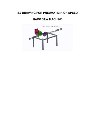
This document provides details on the design and fabrication of a hacksaw machine project. It includes an introduction describing the objective to automate a conventional power hacksaw machine to achieve higher productivity. It then covers the various chapters that will be included in the project report such as literature review, description of equipment like AC motors and pulleys, design and working principles. The last few chapters will cover the merits, applications, materials list, cost estimation and conclusion.
This project is the design and construction of double acting hacksaw for Cutting wood and metal to different length. The power is given by a motor it drives the pulley which holds the main screw. The main screw holds two connecting rods. The other ends of the connecting rods are connected to the frame of the hack saws. The hacksaws are constrained to move in a straight path with the help of sliders. The frame is designed to provide the necessary motion . In this double acting hacksaw machine we can able to cut materials such as wood, steel, etc. This machine makes the cutting operation much easier and also it reduces the production time. Since two work pieces can be cut at the same time the total time is also reduced. The handling of the machine is much simple.
This document describes a project report submitted for the degree of Bachelor of Engineering in Mechanical Engineering. The project involves the design and fabrication of a crankshaft-operated double hacksaw machine. The report includes an introduction outlining the objectives and justification of the project. It also provides a literature review on hacksaw machines and the types of hacksawing. The report then discusses the project methodology, components used, and working of the machine. It concludes with the results, discussion, and scope for future work. The overall aim is to develop an automated hacksaw machine that can cut multiple pieces simultaneously to improve productivity.
Grinding wheels are composed of abrasive grains held together by a bonding material. The most common abrasive grains used are aluminum oxide, silicon carbide, cubic boron nitride, and diamond. There are several types of bonding materials that hold the abrasive grains, including vitrified, resinoid, silicate, shellac, rubber, and metal bonds. Each type of bond has different characteristics that make it suitable for certain grinding applications. Vitrified bonds are the most commonly used as they produce strong and rigid wheels that can withstand high temperatures and liquids.
The document discusses the specifications and construction of grinding wheels. It states that a grinding wheel consists of abrasive grains and a bond that holds the grains together. The abrasive grains can be natural or synthetic and come in various sizes that determine stock removal rate and surface finish. The bond type and wheel structure also influence the grinding process. Proper wheel selection depends on factors like the material, operation, and required surface quality.
This document provides an overview of lathe machines. It begins with a brief history of lathes, noting they originated from primitive tree lathes. It then describes the basic principle of lathes is to rotate a workpiece while a single-point cutting tool removes material parallel to the axis of rotation, producing a cylindrical surface. Various types of lathes are classified based on their design and intended use, such as bench lathes, engine lathes, tool room lathes, capstan and turret lathes, and automatic lathes. The construction and function of key lathe components like the bed, headstock, spindle, tailstock, carriage, and apron are explained.
Works on the principle of slider-crank mechanism with flywheel, motor and a pulley attached to it.
1. The machine can solve the problem of time consumption.
2. Waste of resources in face of labor cost is reduced.
3. The machine can be used in the industry where it is manufactured, at the packaging sector.
4. And it is used as hardware in large quantity like in fabrication of machine
5. It provide alternative for industries aiming toward reducing human effort
6. It generates sustainable and practical automation solutions for the future industrial development.
Broaching is a machining process where a broach tool with multiple cutting teeth is pushed or pulled through a workpiece to cut it into the desired shape. Broaching provides good dimensional accuracy and surface finish. There are different types of broaching machines like horizontal, vertical pull, continuous, and rotary table machines. Broaching is used to manufacture precision components like bearing caps, gears, and splines. It provides interchangeability but the initial costs of broaches and machines are high.
Pneumatic Sheet Metal Shearing Machine - Project reportTejas Inamdar
Hi,
here is a report on Pneumatic Sheet Metal Shearing Machine,
done by us,
if any one wants further detail about it, please contact me on my email -
inamdar.tejas421@gmail.com
This document describes the design of an automatic hacksaw machine. It contains sections on the working principle, power transmission using V-belts, a list of components including an AC motor, ball bearings, flywheel and pulley, a mechanical analysis of torque and speed ratios, design specifications and materials, and a cost estimation. The machine is designed to reduce the time and labor costs of manual hacksawing by automating the reciprocating motion. It provides the advantages of being easy to use, automatic, able to maintain consistent cutting parameters, and economical compared to manual labor. Limitations include an inability to cut larger diameters or be used for mass production.
The document provides information about shaping and planing processes. It discusses the shaping machine, including its principal parts like the base, column, ram and tool head. It describes the shaping operations of producing flat surfaces, slots and contours. The quick return mechanism is explained, along with specifications, tool materials and cutting motions. Formulas for cutting speed, feed, depth and machining time calculations are also presented.
This document is a project report submitted by Satyendra Singh to Dr. A. P. J. Abdul Kalam Technical University for the degree of Bachelor of Technology in Mechanical Engineering. The report describes the design and development of an automatic four-way hacksaw cutting machine using a Scotch yoke mechanism. The machine is intended to allow for the uniform cutting of metal and other materials with less effort compared to traditional hacksaw machines. The report includes sections on the literature review, project methodology, design of parts, cost estimation, and future scope.
This document presents the theoretical analysis and design of a multi-way power hacksaw machine. The proposed machine aims to overcome limitations of conventional single-cut hacksaw machines by enabling the simultaneous cutting of four metal bars. It utilizes a rotating disc connected via connecting rods and universal joints to four reciprocating hacksaw frames. Design calculations determine the required motor torque of 158.3 Nm can be provided by a 2HP motor. The multi-way design is expected to improve production rates for industries by reducing idle time between cuts. Future work may include automation of material feeding and frame lifting mechanisms.
Water jet machining uses a high-pressure stream of water to cut materials. It is a cold cutting process that produces no heat-affected zones. The water jet travels at supersonic speeds and erodes material when the local pressure exceeds the material's strength. Key components include a hydraulic pump to pressurize water, an intensifier to further pressurize it, and a nozzle to direct the jet. It can cut a variety of materials and offers advantages over other cutting methods like reduced burrs, flexibility of cutting complex shapes, and not producing heat or fumes. However, it is not suitable for high-volume production.
This document summarizes cutting tool materials and cutting fluids used in machining processes. It discusses the characteristics and types of cutting tool materials which include high-speed steel, cemented carbide, stellite, ceramic, diamond, CBN and their properties. The requirements of cutting fluids are explained along with types of cutting fluids such as gaseous, liquid and soluble oils. Factors to consider when selecting cutting fluids and different application methods like mist cooling, flood cooling and manual cooling are also outlined.
The document discusses various methods for manufacturing gears, including:
- Gear shaping and hobbing are generating processes that use rotating cutters to form gear teeth profiles. Gear shaping can produce external and internal spur gears with high accuracy, while hobbing is used for external spur gears and worm wheels.
- Gear milling uses form cutters but requires indexing after each tooth, resulting in lower productivity and accuracy than generating processes.
- Other methods discussed include broaching, rolling, powder metallurgy, casting, and machining smaller gears using EDM or broaching. Finishing processes like grinding, lapping, and burnishing are used to improve gear properties.
Design procedure for Cast iron pulley, Flat belt drive, V belt drive, Chain d...Dr.S.Thirumalvalavan
Title: UNIT-I; Design Procedure of Cast iron pulley, Flat belt drive, V belt drive, Chain drive & Wire ropes.
Subject Name: ME8651 - Design of Transmission Systems (DTS) B.E. Mechanical Engineering
Third Year, VI Semester
[Anna University R-2017]
1) Chip formation involves the shear deformation of work material to form a chip as new material is exposed during cutting.
2) There are four basic types of chips in machining: continuous, discontinuous, serrated, and those with built-up edge (BUE).
3) The type of chip formed depends on factors like the work material, tool geometry, cutting speeds and feeds, and machining environment. Understanding chip formation helps optimize the machining process.
The document discusses ultrasonic machining (USM), which uses high-frequency vibrations and an abrasive slurry to erode material. USM can machine hard and brittle materials by using a vibrating tool to drive abrasive particles against the workpiece. The document outlines the principles, components, process parameters, applications, and advantages/disadvantages of USM. It describes how the tool, transducer, abrasives, and other system parts work together to remove material through brittle fracture caused by abrasive particle impacts. Examples are given of complex features that can be machined using USM.
1. A shaper is a machine tool used to produce flat surfaces on workpieces through the reciprocating motion of a toolhead. The first metalworking shaper was developed in 1836.
2. Shapers are classified based on the mechanism that provides reciprocation, the position and travel of the ram, the design of the work table, and the type of cutting stroke.
3. Common types include crank-driven shapers, gear-driven shapers, hydraulic shapers, horizontal shapers, vertical shapers, and universal shapers that allow for additional angles of machining.
A key is used to prevent relative rotation between a shaft and hub while allowing sliding movement. Keys are made of mild steel and subjected to shearing and compressive stresses. There are several types of keys including saddle keys, sunk keys, feather keys, Woodruff keys, and round keys. Saddle keys rely only on friction while sunk keys provide a positive drive through being sunk into both the shaft and hub. Spline and serrated shafts are alternatives that divide the transmitted power over multiple keys or teeth for increased strength.
Ultrasonic machining (USM) uses high-frequency ultrasonic vibrations to remove material from a workpiece with an abrasive slurry. Key aspects of USM include:
1. An ultrasonic generator produces high-frequency vibrations that are transmitted by a transducer to a tool.
2. An abrasive slurry is fed between the vibrating tool and workpiece to facilitate material removal.
3. Common transducer types are magnetostrictive and piezoelectric, with piezoelectric being more efficient.
4. Process parameters like amplitude, frequency, abrasive properties influence the material removal rate and wear ratio.
Thread cutting is a lathe operation that produces helical threads on cylindrical workpieces using a tool with the same shape as the thread. There are different types of screw threads and thread nomenclature. Lathe setting for thread cutting involves introducing a translating gear, where the gear ratio equals the pitch of the workpiece divided by the pitch of the lead screw, which can be expressed as 5 times the number of threads per inch divided by 127, where 5 is the progression and the number of threads per inch is the reciprocal of the pitch. Lathe speeds are measured in revolutions per minute and can be changed using stepped pulleys, gear levers, changing belts on belt-driven lathes, or moving speed levers on
MILLING MACHINE PPT 2: PARTS AND CLASSIFICATION OF MILLING MACHINESPOLAYYA CHINTADA
The document discusses the parts, types, and classifications of milling machines. It describes the main components of milling machines including the base, column, knee, saddle, table, overhanging arm, front brace, spindle, and arbor. It classifies milling machines as column and knee type, fixed bed type, planner type, and production type. Within these classifications, it provides details about horizontal milling machines, vertical milling machines, universal milling machines, omniversal milling machines, simplex milling machines, and other specific types of milling machines such as drum milling machines and tracer controlled milling machines.
Final year project report on scissor liftDhiraj Rane
1) Scissor lifts use a pantograph mechanism of linked, folding supports arranged in a crisscross pattern to provide vertical displacement of a load. Force is applied to elongate the pattern and lift the load.
2) Passengers carrying heavy luggage often struggle climbing stairs between railway platforms. A portable mechanical lift could help transport luggage between platforms without using stairs.
3) The proposed mechanism aims to optimize a portable scissor lift with a sliding platform for carrying luggage between platforms without using stairs. It will be manually operated, portable, and require less maintenance than hydraulic or pneumatic systems.
1) Screw threads are commonly used for fastening parts together, clamping objects, transmitting motion and power, and making precision measurements of length.
2) There are various methods for manufacturing screw threads, including machining using lathes and taps, thread milling, rolling, and grinding.
3) Thread manufacturing methods are chosen based on factors such as the required accuracy, material properties, batch size, and thread specifications. Machining is suitable for high accuracy threads while rolling is faster but provides less accuracy.
Broaching is a machining process that uses a toothed tool called a broach to remove material in a single pass. Broaching was first used in the 1850s and was commonly used to rifle gun barrels during World War 1. Broaching machines can perform horizontal, vertical, continuous, and rotary broaching. Broaching tools are designed based on the material, size and shape of the cut, required tolerances, and production rates. Broaching provides high production rates and accuracy for complex hole shapes and surfaces.
This document provides details on the design and working of a pneumatic high speed hack saw machine. It includes chapters on the literature review of saws, pneumatics and cutting techniques. It describes the various pneumatic control components used in the machine like cylinders, valves, hoses and pressure gauges. It discusses the design calculations and fabrication process. The working principle involves using compressed air to power the saw blade. The document concludes that this machine can be used widely in small industries for automated metal cutting applications due to its low cost and reduced labor requirements.
This document discusses the design and development of a motorized double hacksaw machine that can cut two metal bars simultaneously to achieve high cutting speeds and mass production. It describes the key components of the machine, including the scotch yoke mechanism that converts rotary motion into reciprocating motion to power the hacksaws. Testing showed the motorized double hacksaw machine provided faster and more efficient cutting than a conventional hacksaw. The document also provides background on common sawing machines like power hacksaws and bandsaws, and their applications in metal cutting.
The document discusses various topics related to machining processes including:
- The objectives of understanding machining processes and estimating machining time and costs.
- The mechanics of chip formation during metal cutting using single-point cutting tools.
- Factors that influence tool life such as cutting speed, feed rate, depth of cut, tool geometry, and work material.
- Different types of chips produced during machining such as continuous, discontinuous, and chips with a built-up edge.
- Properties required for cutting tool materials including hardness, wear resistance, toughness, thermal conductivity and elements commonly used.
- Common cutting tool materials including high-carbon steel, high-speed steel, cemented carbides
The document describes a project report on the design of a common bending tool for two sheet metal components (left and right). It discusses the history of metal shaping tools and introduces press tools and their types like blanking, piercing, bending, etc. It also covers topics like strip layout, types of strip layout arrangements, factors that affect strip arrangement, die design parameters and calculations. The key objectives are to maximize material utilization, reduce production costs, and increase part output through an efficient strip layout and tool design.
This document provides an overview of a mini project on designing and fabricating a mini bench saw machine. It includes an abstract, block diagram, introduction, objectives, parts used, working principle, result, and conclusion. The project aims to demonstrate an efficient mini bench saw model using an electric motor to power and mount various blades for cutting. It describes the motor, saw blade, spring, switch, and supporting frame components. The working principle explains how the rotating blade is mounted on a swinging arm to cut wood pieces placed on the base. The result is straight and desired cutting of different materials. The conclusion discusses the advantages of this bench saw over conventional sawing methods.
Possible Interview Questions/Contents From Manufacturing Technology IIDr. Ramesh B
1. Machining is a process that removes material from a workpiece through cutting or other shear mechanisms in order to change its shape or size. The three fundamental machining parameters are cutting speed, depth of cut, and feed.
2. Material removal rate is the volume of material removed per minute during machining operations like turning, where it is calculated as MRR=Vfd. Chip formation affects surface finish, cutting forces, temperature, tool life, and tolerances.
3. Tool wear occurs due to interactions between the tool and chip like adhesion and abrasion, leading to flank wear, crater wear, chipping, and breakage. Tool wear degrades surface finish and increases tolerances and machining
This document provides information about a multi-way power hacksaw machine. It begins with an introduction that explains how this machine can cut four metal bars simultaneously, achieving high production rates. It then discusses the scotch yoke mechanism that converts linear motion to rotational motion. Various types of hacksaw machines are described, including power hacksaw machines, hydraulic hacksaw machines, circular band saw machines, and more. The construction of hacksaw machines is explained, covering components like the bed, saw frame, and drive system.
Investigations on Milling Tool: - A Literature ReviewIJRES Journal
Milling machines are tools designed to machine metal, wood, and other solid materials. Often automated, milling machines can be positioned in either vertical or horizontal orientation to carve out materials based on a pre-existing design. The main aim of this paper is to focus on the study of effects of cutting tools on various materials while the parameters are kept constant and also by varying the parameters. A literature review was conducted to find the effects of different cutting tools on milling of different materials. It was found out that most of the work was done using single tool and single material and results were recorded. The literature review gives us idea to use more than one material and subject it to the single tool. And then a comparison can be made on the results that are recorded.
The document proposes the design and fabrication of a multi-four way hack saw machine. It aims to develop a machine that can cut materials like metal bars, plastic pipes, and wood pieces at high speed and in large quantities simultaneously. The machine would use a metal frame, AC motor, circular disc, connecting rods, hacksaw blades and vice to cut up to four workpieces simultaneously. This design would help industries and workshops improve production efficiency and output. A methodology is presented covering data collection, materials used, equipment, and the model design which incorporates a frame, mounted hacksaw blades, circular cam plate, motor, connecting rods and vice.
This document discusses machining and metal cutting. It defines machining as a process that converts raw materials into finished products with specific dimensions, shapes, and surfaces. It describes cutting speed, feed rate, depth of cut, and different types of chips formed during machining. It also covers tool geometry including rake angle, cutting edge angles, and tool signature. Mechanisms of chip formation and sources of heat generation during machining are explained. Different types of single point cutting tools and their nomenclature are discussed in detail.
The document provides information about workshop technology and machine shop theory. It discusses various topics like metal cutting, lathe machine, drilling machine, shaper, planer, slotter machine, and milling machine. For lathe machine, it describes the types of lathe, construction of lathe, accessories and attachments used in lathe like lathe centers, lathe dog, chuck, faceplate, angle plate, and mandrels. It also provides details about metal cutting processes, types of chips, cutting tools, and use of coolants in metal cutting.
This document provides an overview of metal cutting theory and processes. It discusses orthogonal and oblique cutting, types of cutting tools including single point and multipoint tools, tool geometry and signatures. It also covers mechanics of metal cutting including shear angle and chip formation, tool materials, tool wear and tool life, factors affecting machining, and types of metal cutting processes and chips. Cutting fluid types and applications are also summarized.
This document discusses the theory of metal cutting. It covers topics such as orthogonal and oblique cutting, types of cutting tools including single-point and multipoint tools, tool geometry including rake angles and relief angles, mechanics of metal cutting including shear angle and chip formation, types of chips, tool wear and tool life, cutting fluids, and various metal cutting processes. Key points covered include shear angle significance in metal cutting, factors affecting metal cutting, and nomenclature used for describing single-point cutting tool geometry.
This chapter aims to provide basic backgrounds of different types of machining processes and highlights on an understanding of important parameters which affects machining of metals with their chip removals.
Metal cutting or Machining is the process of producing workpiece by removing unwanted material from a block of metal. in the form of chips. This process is most important since almost all the products get their final shape and size by metal removal. either directly or indirectly.
The major drawback of the process is loss of material in the form of chips. In this chapter. we shall have a fundamental understanding of the basic metal process.
Rotary instruments / dental implant courses by Indian dental academy Indian dental academy
The document discusses the history and development of rotary dental instruments from ancient times to modern advances. It covers key topics such as the principles of rotary cutting, instrument parts and design, types of instruments, ISO standardization, manufacturing methods, factors that influence efficiency, clinical considerations, and sterilization methods. Rotary instruments have advanced dentistry by enabling efficient removal and shaping of tooth structure in a safe and controlled manner.
This document contains the answer key for a unit test on Manufacturing Technology-II. It discusses various topics related to cutting tools and machining processes, including:
1. Types of cutting tools such as single point and multipoint tools.
2. Factors that affect tool life such as rake angle, tool wear, and cutting fluids.
3. Different types of chips produced during machining such as continuous, discontinuous, and chips with built-up edge.
4. Tool materials used for different temperature ranges such as carbon steel, high-speed steel, cemented carbides, and ceramics.
5. Merchant's circle diagram which models the forces during chip formation.
This document summarizes the design and fabrication of an automated chiseling machine. The machine aims to chisel the surface of a trestle box to create a rough surface that enables the box to grip the jaws of a hydraulic jack, lifting heavy metal sheets to form storage tanks with minimal human involvement. The machine reduces worker fatigue by automating various machining processes used to modify the trestle box.
Tools, Valves & Materials for Marine UseMarine Study
The document discusses various tools, parts, and materials required for ship maintenance. It provides detailed descriptions and examples of common hand tools like wrenches, pliers, scissors, hammers, saws, and pullers. It also discusses power tools like grinders, drills, and lathe machines. Further, it outlines welding and cutting equipment like arc welding setups, plasma cutters, and oxy-acetylene torch setups. Proper procedures for hot work and manipulating variables for good welds are also covered. The document serves as a comprehensive reference for marine engineers on equipment and tools needed for ship repair and maintenance work.
The document discusses various topics related to metal cutting and lathe machines. It defines metal cutting as removing unwanted material from a block of metal in the form of chips. It discusses important tool characteristics, tool life, tool angles, chip formation, factors affecting tool life, tool wear types, cutting fluid functions, and more. It also defines different types of lathes such as engine lathes, bench lathes, tool room lathes, and semi-automatic lathes which allow mostly automatic machining with some manual functions like loading/unloading.
1. “DESIGN AND FABRICATION OF HACKSAW
MACHINE
PROJECT REPORT 2017-2018
Submitted by:
(Team name)
Guided by:
Submitted in partial fulfillment of the requirement for the
Award of Diploma in -----------------------------------------
By the State Board of Technical Education Government of
Tamilnadu, Chennai.
Department:
College name:
Place:
COLLEGE LOGO
2. COLLEGE NAME
COIMBATORE
DEPARTMENT OF MECHANICAL ENGINEERING
PROJECT REPORT-2017-2018
This Report is certified to be the Bonafide work done by
Selvan/Selvi ---------------- Reg.No. ------------ Of VI
Semester class of this college.
Guide Head of the Department
Submitter for the Practical Examinations of the board of
Examinations,State Board of Technical Education,Chennai,
TamilNadu.On --------------(date) held at the ------------
(college name),Coimbatore
Internal Examiner External Examiner
5. ACKNOWLEDGEMENT
At this pleasing moment of having successfully completed
our project, we wish to convey our sincere thanks and gratitude
to the management of our college and our beloved
chairman------------------------.who provided all the facilities to us.
We would like to express our sincere thanks to our
principal ------------------for forwarding us to do our project and
offering adequate duration in completing our project.
We are also grateful to the Head of Department
prof…………., for her/him constructive suggestions
&encouragement during our project.
With deep sense of gratitude, we extend our earnest
&sincere thanks to our guide --------------------, Department of
Mechanical for her/him kind guidance and encouragement
during this project we also express our indebt thanks to our
TEACHING staff of MECHANICAL ENGINEERING
DEPARTMENT, ---------- (college Name).
8. CONTENTS
CHAPTER NO TITLE
SYNOPSIS
LIST OF FIGURES
1 Introduction
2 Literature review
3 Description of equipments
3.1 Ac Motor
3.2 Belt
3.3 Pulley
4 Design and drawing
4.1 Components and Specification
4.2 Block diagram
4.3 Overall diagram
5 Working principle
6 Merits and demerits
7 applications
8 List of materials
9 Cost Estimation
10 Conclusion
Bibliography
photography
12. SYNOPSIS
The objective of this work is to automate the conventional power hacksaw
machine in order to achieve high productivity of work-pieces than the power
hacksaw machine using Double hacksaw blade. The operator need not
measure the length of the work-piece that is to be cut. The machine feeds the
work-piece with the help of a shaft, which is driven by a DC motor . An DC
motor is used to bring about the reciprocating motion required for cutting the
work-pieces. With the help of this multi-way power hacksaw machine the
four metal bars can be cut simultaneously to get high speed cutting rate and
to achieve mass production for maximum profit in related companies. This
project is very much useful and easy to install by user. The reference number
should be shown in square bracket
14. CHAPTER -1
INTRODUCTION
In present condition many electrically operated power hacksaw machines of different
companies with different specifications are available for the use in shop floor. These
machines are so precise that they can cut metal bars with minimum time made up of
different materials but they have one and major disadvantage that those are able to cut
single piece of bar at a time. For industries to achieve the mass production, it is necessary
to cut metal bars with high rate. So it is impossible to depend upon conventional single
frame power hacksaw machines and need the improvement in technology and design of
such machines. With the help of this multi-way power hacksaw machine the four metal
bars can be cut simultaneously to get high speed cutting rate and to achieve mass
production for maximum profit in related companies. As this machine overcomes all the
limitations and drawbacks of conventional hacksaw machines, it is also helpful for small
scale industries due to its simple working and operating conditions along with its
compatibility, efficiency and affordable price. This project is about cutting the wood,
metal, pipe, angle, channel, flat plates, rods and such other things. This project is very
much useful and easy to install by user. The reference number should be shown in square
bracket [1]. However the authors name can be used along with the reference number in
the running text. The order of reference in the running text should match with the list of
references at the end of the paper.
16. CHAPTER -2
LITRATURE SURVEY
Saw:
A saw is a tool that uses a hard blade or wire with an abrasive
edge to cut through softer materials. The cutting edge of a saw is
either a serrated blade or an abrasive. A saw may be worked by
hand, or powered by steam, water, electric or other power.
In a modern serrated saw, each tooth is bent to a precise angle
called its "set". The set of the teeth is determined by the kind of cut
the saw is intended to make. For example, a "rip saw" has a tooth set
that is similar to the angle used on a chisel. The idea is to have the
teeth rip or tear the material apart. Some teeth are usually splayed
slightly to each side the blade, so that the cut width (kerf) is wider
than the blade itself and the blade does not bind in the cut.
An abrasive saw uses an abrasive disc or band for cutting,
rather than a serrated blade.
According to Chinese tradition, the saw was invented by Lu
Ban. In Greek mythology, Talos, the nephew of Daedalos, invented
17. the saw. In fact, saws date back to prehistory, and likely evolved from
Neolithic tools or bone tools. The early ancestors of man, in the
Pleistocene era, likely first used a jaw bone of a bovid animal as a
saw.
TYPES OF SAW BLADES AND THE CUTS THEY
MAKE
BLADE TEETH ARE OF TWO GENERAL TYPES:
Tool steel or carbide. Carbide is harder and holds a sharp edge much
longer.
CROSSCUT:
In woodworking, a cut made at (or near) a right angle to the
direction of the grain of the work piece. A crosscut saw is used
to make this type of cut.
RIP CUT:
In woodworking, a cut made parallel to the direction of the grain
of the work piece. A rip saw is used to make this type of cut.
18. PLY TOOTH:
A circular saw blade with many small teeth designed for cutting
plywood with minimal splintering.
MATERIALS USED FOR SAWS
THERE ARE SEVERAL MATERIALS USED IN SAWS, WITH EACH
OF ITS OWN SPECIFICATIONS.
BRASS:
Mostly used in back saws because of its low price, its flow
characteristics that make the material relatively easy to cast,
and unlike other types of saw, the forces that take place in back
saws are relatively low because of the pulling motion used.
STEEL:
19. Used in almost every existing kind of saw. Because steel is
cheap, easy to shape, and very strong, it has the right
properties for most kind of saws.
DIAMOND:
Used only in saws for the really heavy cutting. It is very
expensive and comes in two shapes: ropes and circular saws.
Mostly used for cutting concrete and other materials with rock-
like structures or in softer materials, such as wood, where the
precision and high volume of work justifies the expense of
diamond-edged cutting tools. Diamond saws are made by
combining powder metal with diamond crystals, which are then
heated and pressed into a molding to form the diamond
segments.
20. USES:
• Saws are most commonly used for cutting hard materials. They
are used extensively in forestry, construction, demolition,
medicine, and hunting.
• Some saws are used as instruments to make music.
• Chainsaw carving is a flourishing modern art form. Special
saws have been developed for this purpose.
HACKSAW:
A hacksaw is a fine-tooth saw with a blade under tension in a
frame, used for cutting materials such as metal or bone. Some have
pistol grips which keep the hacksaw firm and easy to grip.
A power hacksaw is a type of hacksaw that is powered either
by its own electric motor (also known as electric hacksaw) or
connected to a stationary engine. Most power hacksaws are
stationary machines but some portable models do exist. Stationary
models usually have a mechanism to lift up the saw blade on the
21. return stroke and some have a coolant pump to prevent the saw
blade from overheating.
While stationary electric hacksaws are reasonably uncommon
they are still produced but saws powered by a stationary engines
have gone out of fashion. The reason for using one is that they
provide a cleaner cut than an angle grinder or other types of saw.
CUTTING:
Cutting sheet metal can be done in various ways from hand
tools called tin snips up to very large powered shears. With the
advances in technology, sheet metal cutting has turned to computers
for precise cutting.
Cutting is the separation of a physical object, or a portion of a
physical object, into two portions, through the application of an
acutely directed force. An implement commonly used for cutting is the
knife or in medical cases the scalpel. However, any sufficiently sharp
object is capable of cutting if it has a hardness sufficiently larger than
the object being cut, and if it is applied with sufficient force. Cutting
22. also describes the action of a saw which removes material in the
process of cutting.
Cutting is a compressive and shearing phenomenon, and
occurs only when the total stress generated by the cutting implement
exceeds the ultimate strength of the material of the object being cut.
The simplest applicable equation is stress = force/area: The stress
generated by a cutting implement is directly proportional to the force
with which it is applied, and inversely proportional to the area of
contact. Hence, the smaller the area (i.e., the sharper the cutting
implement), the less force is needed to cut something.
When referring to propagating plants, cutting is one of the
methods that can be used. It involves cutting a part of the plant
typically a healthy shoot, with sharp and sterile scissors or any other
cutting device, and then placing the removed part in water. Some
cuttings do not require water. Certain shoots when cut are able to
grow when placed in vermiculite or potting soil. However, the former
is the easiest to do as most shoots when cut from the main plant
need time to grow roots, and then they are able to be transferred to
potting soil.
23. ULTIMATE AIM
The “Design and Fabrication of Hacksaw Machine machine is low cost
automation equipment which can be widely used in small scale
industries and automobile maintenance shops. Pressing speed is
high. The manpower requirement is reduced also reducing the
machining time.
25. CHAPTER-3
DESCRIPTION OF EQUIPMENTS
3.1 AC MOTOR (IM)
An induction motor (IM) is a type of alternating current motor
where power is supplied to the rotating device by means of
electromagnetic induction. It is also called asynchronous motor.
An electric motor converts electrical power to mechanical power
in its rotor (rotating part). There are several ways to supply power to
the rotor. In a DC motor this power is supplied to the armature directly
26. from a DC source, while in an induction motor this power is induced
in the rotating device. An induction motor is sometimes called a
rotating transformer because the stator (stationary part) is essentially
the primary side of the transformer and the rotor (rotating part) is the
secondary side. Induction motors are widely used, especially
polyphase induction motors, which are frequently used in industrial
drives.
Induction motors are now the preferred choice for industrial
motors due to their rugged construction, absence of brushes (which
are required in most DC motors) and — thanks to modern power
electronics — the ability to control the speed of the motor.
PRINCIPLE OF OPERATION AND COMPARISON TO
SYNCHRONOUS MOTORS
The basic difference between an induction motor and a
synchronous AC motor is that in the latter a current is supplied onto
the rotor. This then creates a magnetic field which, through magnetic
interaction, links to the rotating magnetic field in the stator which in
turn causes the rotor to turn. It is called synchronous because at
steady state the speed of the rotor is the same as the speed of the
rotating magnetic field in the stator.
27. By way of contrast, the induction motor does not have any
direct supply onto the rotor; instead, a secondary current is induced in
the rotor. To achieve this, stator windings are arranged around the
rotor so that when energised with a polyphase supply they create a
rotating magnetic field pattern which sweeps past the rotor. This
changing magnetic field pattern induces current in the rotor
conductors. These currents interact with the rotating magnetic field
created by the stator and in effect causes a rotational motion on the
rotor.
However, for these currents to be induced, the speed of the
physical rotor and the speed of the rotating magnetic field in the
stator must be different, or else the magnetic field will not be moving
relative to the rotor conductors and no currents will be induced. If by
some chance this happens, the rotor typically slows slightly until a
current is re-induced and then the rotor continues as before. This
difference between the speed of the rotor and speed of the rotating
magnetic field in the stator is called slip. It is unitless and is the ratio
between the relative speed of the magnetic field as seen by the rotor
(the slip speed) to the speed of the rotating stator field. Due to this an
28. induction motor is sometimes referred to as an asynchronous
machine.
CONSTRUCTION
The stator consists of wound 'poles' that carry the supply
current to induce a magnetic field that penetrates the rotor. In a very
simple motor, there would be a single projecting piece of the stator (a
salient pole) for each pole, with windings around it; in fact, to optimize
the distribution of the magnetic field, the windings are distributed in
many slots located around the stator, but the magnetic field still has
the same number of north-south alternations. The number of 'poles'
can vary between motor types but the poles are always in pairs (i.e.
2, 4, 6, etc.).
Induction motors are most commonly built to run on single-
phase or three-phase power, but two-phase motors also exist. In
theory, two-phase and more than three phase induction motors are
possible; many single-phase motors having two windings and
requiring a capacitor can actually be viewed as two-phase motors,
since the capacitor generates a second power phase 90 degrees
from the single-phase supply and feeds it to a separate motor
winding. Single-phase power is more widely available in residential
29. buildings, but cannot produce a rotating field in the motor (the field
merely oscillates back and forth), so single-phase induction motors
must incorporate some kind of starting mechanism to produce a
rotating field. They would, using the simplified analogy of salient
poles, have one salient pole per pole number; a four-pole motor
would have four salient poles. Three-phase motors have three salient
poles per pole number, so a four-pole motor would have twelve
salient poles. This allows the motor to produce a rotating field,
allowing the motor to start with no extra equipment and run more
efficiently than a similar single-phase motor.
THERE ARE THREE TYPES OF ROTOR
SQUIRREL-CAGE ROTOR
The most common rotor is a squirrel-cage rotor. It is made up of
bars of either solid copper (most common) or aluminum that span the
length of the rotor, and are connected through a ring at each end.
The rotor bars in squirrel-cage induction motors are not straight, but
have some skew to reduce noise and harmonics.
SLIP RING ROTOR
A slip ring rotor replaces the bars of the squirrel-cage rotor with
windings that are connected to slip rings. When these slip rings are
30. shorted, the rotor behaves similarly to a squirrel-cage rotor; they can
also be connected to resistors to produce a high-resistance rotor
circuit, which can be beneficial in starting
SOLID CORE ROTOR
A rotor can be made from solid mild steel. The induced current
causes the rotation.
3.2 PULLEY
A pulley is a wheel with a groove along its edge, also called a
sheave, for holding a rope or cable. Pulleys are usually used in sets
designed to reduce the amount of force needed to lift a load. The
same amount of work is necessary for the load to reach the same
height as it would without the pulleys. The magnitude of the force is
reduced, but it must act through a longer distance. The effort needed
to pull a load up is roughly the weight of the load divided by the
number of wheels. The more wheels there are, the less efficient a
system is, because of more friction between the rope and the wheels.
The pulleys and lines are weightless, and that there is no
energy loss due to friction. It is also assumed that the lines do not
stretch. With this assumption, it follows that, in equilibrium, the total
force on the pulley must be zero. This means that the force on the
31. axle of the pulley is shared equally by the two lines looping through
the pulley. The lines are not parallel, the tensions in each line are still
equal, but now the vector sum of all forces is zero.
A second basic equation for the pulley follows from the
conservation of energy the product of the weight lifted times the
distance it is moved is equal to the product of the lifting force times
the distance the lifting line is moved. The weight lifted divided by the
lifting force is defined as the advantage of the pulley system. It is
important to notice that the amount of work done in an ideal pulley is
always the same. The work is given by the effort times the distance
moved. The pulley simply allows trading effort for distance.
3.3 BELT
Belts are used to mechanically link two or more rotating items.
They may be used as a source of motion, to transmit power at up to
98% efficiency between two points, or to track relative movement.
32. As a source of motion, a conveyor belt is one application where
the belt is adapted to continually carry a load between two points. A
belt may also be looped between two points so that the direction of
rotation is reversed at the other point. Power transmission is achieved
by specially designed belts and pulleys. The demands on a belt drive
transmission system.
Belts normally transmit power only on the tension side of the
loop. Designs for continuously variable transmissions exist that use
belts that are a series of solid metal blocks, linked together as in a
chain, transmitting power on the compression side of the loop.
34. CHAPTER-IV
DESIGN OF EQUIPMENT AND DRAWING
4.1 COMPONENTS AND ITS SPECIFICATION
The cutting machine consists of the following components to full
fill the requirements of complete operation of the machine.
1. AC MOTOR
2. HACKSAW
3. BELT
4. PULLEY
38. CHAPTER-V
WORKING PRINCIPLE
A hacksaw machine is work on principle of QUICK RETURN
MECHANISUM in this rotary motion of shaft is to be convert into the
reciprocating motion of hacksaw frame. Working principle of hacksaw
machine is very simple. First of all the hacksaw machine is put on ground
and after that whatever metal, wood, pvc, is cut is fixed on vice at required
length, after that the electric motor is connect with electricity. Now start the
electric motor so due to that the shaft of motor and hollow disc will be rotate
and also rotate the eccentric Centre and link connect to it. Due to rotation of
links the hacksaw frame will be reciprocate on the metal and cutting of metal
is done.
40. CHAPTER -6
MERITS AND DEMERITS
MERITS:
Weight of machine is less.
It reduces the work of labor.
Easy to make because of simple construction.
High production rate.
Cost is less.
Easy maintenance and maintenance cost is less.
It resists all atmospheric effects.
DEMERITS:
Time consume more.
Speed variation is required for cutting the different metal
42. CHAPTER-VII
APPLICATIONS
• This machine is very useful for small scale industries
• These machines used to cut the roller sheet metal
• All industrial application
44. CHAPTER-VIII
LIST OF MATERIALS
FACTORS DETERMINING THE CHOICE OF MATERIALS
The various factors which determine the choice of material are
discussed below.
1. Properties:
The material selected must posses the necessary properties for
the proposed application. The various requirements to be satisfied
Can be weight, surface finish, rigidity, ability to withstand
environmental attack from chemicals, service life, reliability etc.
The following four types of principle properties of materials
decisively affect their selection
a. Physical
b. Mechanical
c. From manufacturing point of view
d. Chemical
The various physical properties concerned are melting point, thermal
Conductivity, specific heat, coefficient of thermal expansion, specific
gravity, electrical conductivity, magnetic purposes etc.
45. The various Mechanical properties Concerned are strength in tensile,
Compressive shear, bending, torsional and buckling load, fatigue
resistance, impact resistance, eleastic limit, endurance limit, and
modulus of elasticity, hardness, wear resistance and sliding
properties.
The various properties concerned from the manufacturing point
of view are,
Cast ability
Weld ability
Forge ability
Surface properties
Shrinkage
Deep drawing etc.
2. Manufacturing case:
Sometimes the demand for lowest possible manufacturing cost or
surface qualities obtainable by the application of suitable coating
substances may demand the use of special materials.
3. Quality Required:
This generally affects the manufacturing process and ultimately
the material. For example, it would never be desirable to go casting of
46. a less number of components which can be fabricated much more
economically by welding or hand forging the steel.
4. Availability of Material:
Some materials may be scarce or in short supply. It then
becomes obligatory for the designer to use some other material which
though may not be a perfect substitute for the material designed. the
delivery of materials and the delivery date of product should also be
kept in mind.
5. Space consideration:
Sometimes high strength materials have to be selected because the
forces involved are high and space limitations are there.
6. Cost:
As in any other problem, in selection of material the cost of
material plays an important part and should not be ignored.
Some times factors like scrap utilization, appearance, and non-
maintenance of the designed part are involved in the selection of
proper materials.
48. CHAPTER-IX
COST ESTIMATION
1. MATERIAL COST:
2. LABOUR COST:
Lathe, drilling, welding, grinding, power hacksaw, gas cutting cost
3. OVERGHEAD CHARGES:
The overhead charges are arrived by ”manufacturing cost”
Manufacturing Cost =Material Cost +Labour Cost
=
=
Overhead Charges =20%of the manufacturing cost
=
4. TOTAL COST:
Total cost = Material Cost +Labour Cost +Overhead Charges
=
=
Total cost for this project =
50. CHAPTER-X
CONCLUSION
The project carried out by us made an impressing task in the
field of small scale industries and automobile maintenance shops. It
is very useful for the workers work in the lath and small scale
industries.
This project will reduce the cost involved in the concern. Project
has been designed to perform the entire requirement task at the
shortest time available.