Downloaded 542 times


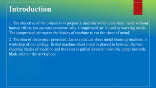


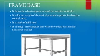
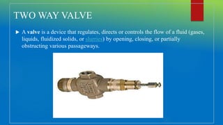


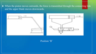


The document describes a project on a pneumatic sheet metal cutting machine, detailing its design, components, working mechanism, cost estimation, advantages, and applications. The machine operates using compressed air to cut sheet metal without human effort, aiming for efficiency and precision. Key components include a pneumatic cylinder, sheet cutter, and air compressor, all noted for their cost-effectiveness and suitability in various industries such as automotive and aerospace.


![group CC [Autosaved].pptx in the field of engineering](https://cdn.slidesharecdn.com/ss_thumbnails/groupccautosaved-240502141157-4acbc85b-thumbnail.jpg?width=640&height=640&fit=bounds)


