Download to read offline
![International Journal of Mechanical Engineering and Technology (IJMET), ISSN 0976
ISSN 0976 – 6359(Online), Volume 6, Issue
signboards and there is a chance for accident
can control the speed of vehicles. Here we are designing a speed control system for vehicles which
can intimate the driver about the zones and limit speed of the vehicle automa
This paper develops an intelligent speed adaptation, which can monitor the vehicle speed and
implements an action when the vehicle is detected to be exceeding the speed displayed in the speed
display (sign) boards [2]. The speed display boards
protocol. The driver should take great attention on the speed of the vehicle especially when driving
through busy junctions, railway crossings, school and college zones etc[3].The citizens are ought to
obey the speed enforcement rules in order to avoid the accidents, any violation in this are considered
as a greater offence. Traffic Police are authorized to check every vehicle and take actions against the
violation [4]. But it may not be practically possible alwa
a way that the vehicle speed is automatically controlled through over a wireless communication
[5][6].
2. EXISTING SYSTEM
The figure 1 shows electrical circuit demonstration for the working of a two wheeler. It has
an excitor coil which is excited by flywheel of two
voltage to the circuit. It has also a pulse rotor. It has one magnet
trigger circuit of SCR. The rotation of which depends on the requirement of speed.
Fig.1.
There is an ignition stop switch when it is closed and charges the capacitor .There is a
d1 through which the capacitor is charged and it is connected to primary of step up transformer.
There will be an SCR, in a solid state device which when triggered discharges the capacitor and
produces ignition .There will be an ignition coil and sp
fuel in the engine.
3. PROPOSED SYSTEM
The proposed system consists
connected, one in the speed display board and the other inside the vehicle. The module at display
Board includes, Microcontroller based Embedded System with Zigbee wireless communication
module etc. Speed limit of each sign board can be configured by the authority by using keypad. The
system uses wireless methods for the communication using ZIGBEE Trans
International Journal of Mechanical Engineering and Technology (IJMET), ISSN 0976
6359(Online), Volume 6, Issue 4, April (2015), pp. 01-10© IAEME
2
is a chance for accident. So there is an utmost need to design a system which
can control the speed of vehicles. Here we are designing a speed control system for vehicles which
can intimate the driver about the zones and limit speed of the vehicle automatically
This paper develops an intelligent speed adaptation, which can monitor the vehicle speed and
implements an action when the vehicle is detected to be exceeding the speed displayed in the speed
[2]. The speed display boards are working as per the highway speed limiting
protocol. The driver should take great attention on the speed of the vehicle especially when driving
through busy junctions, railway crossings, school and college zones etc[3].The citizens are ought to
speed enforcement rules in order to avoid the accidents, any violation in this are considered
Police are authorized to check every vehicle and take actions against the
[4]. But it may not be practically possible always. The proposed system is designed in such
a way that the vehicle speed is automatically controlled through over a wireless communication
The figure 1 shows electrical circuit demonstration for the working of a two wheeler. It has
an excitor coil which is excited by flywheel of two wheeler. It has a magnet which induces ac
voltage to the circuit. It has also a pulse rotor. It has one magnet and induces a dc voltage in the
trigger circuit of SCR. The rotation of which depends on the requirement of speed.
Demonstration circuit of existing system
There is an ignition stop switch when it is closed and charges the capacitor .There is a
d1 through which the capacitor is charged and it is connected to primary of step up transformer.
There will be an SCR, in a solid state device which when triggered discharges the capacitor and
produces ignition .There will be an ignition coil and spark plug which produces spark for ignition of
consists of two microcontroller based embedded modules [2]
connected, one in the speed display board and the other inside the vehicle. The module at display
Microcontroller based Embedded System with Zigbee wireless communication
limit of each sign board can be configured by the authority by using keypad. The
system uses wireless methods for the communication using ZIGBEE Trans- Receive module.
International Journal of Mechanical Engineering and Technology (IJMET), ISSN 0976 – 6340(Print),
. So there is an utmost need to design a system which
can control the speed of vehicles. Here we are designing a speed control system for vehicles which
tically [1].
This paper develops an intelligent speed adaptation, which can monitor the vehicle speed and
implements an action when the vehicle is detected to be exceeding the speed displayed in the speed
are working as per the highway speed limiting
protocol. The driver should take great attention on the speed of the vehicle especially when driving
through busy junctions, railway crossings, school and college zones etc[3].The citizens are ought to
speed enforcement rules in order to avoid the accidents, any violation in this are considered
Police are authorized to check every vehicle and take actions against the
ys. The proposed system is designed in such
a way that the vehicle speed is automatically controlled through over a wireless communication
The figure 1 shows electrical circuit demonstration for the working of a two wheeler. It has
wheeler. It has a magnet which induces ac
and induces a dc voltage in the
trigger circuit of SCR. The rotation of which depends on the requirement of speed.
There is an ignition stop switch when it is closed and charges the capacitor .There is a diode
d1 through which the capacitor is charged and it is connected to primary of step up transformer.
There will be an SCR, in a solid state device which when triggered discharges the capacitor and
ark plug which produces spark for ignition of
of two microcontroller based embedded modules [2]
connected, one in the speed display board and the other inside the vehicle. The module at display
Microcontroller based Embedded System with Zigbee wireless communication
limit of each sign board can be configured by the authority by using keypad. The
Receive module.](https://image.slidesharecdn.com/smart-vehicle-and-smart-signboard-system-with-zonal-speed-regulation-160216130536/75/Smart-vehicle-and-smart-signboard-system-with-zonal-speed-regulation-2-2048.jpg)
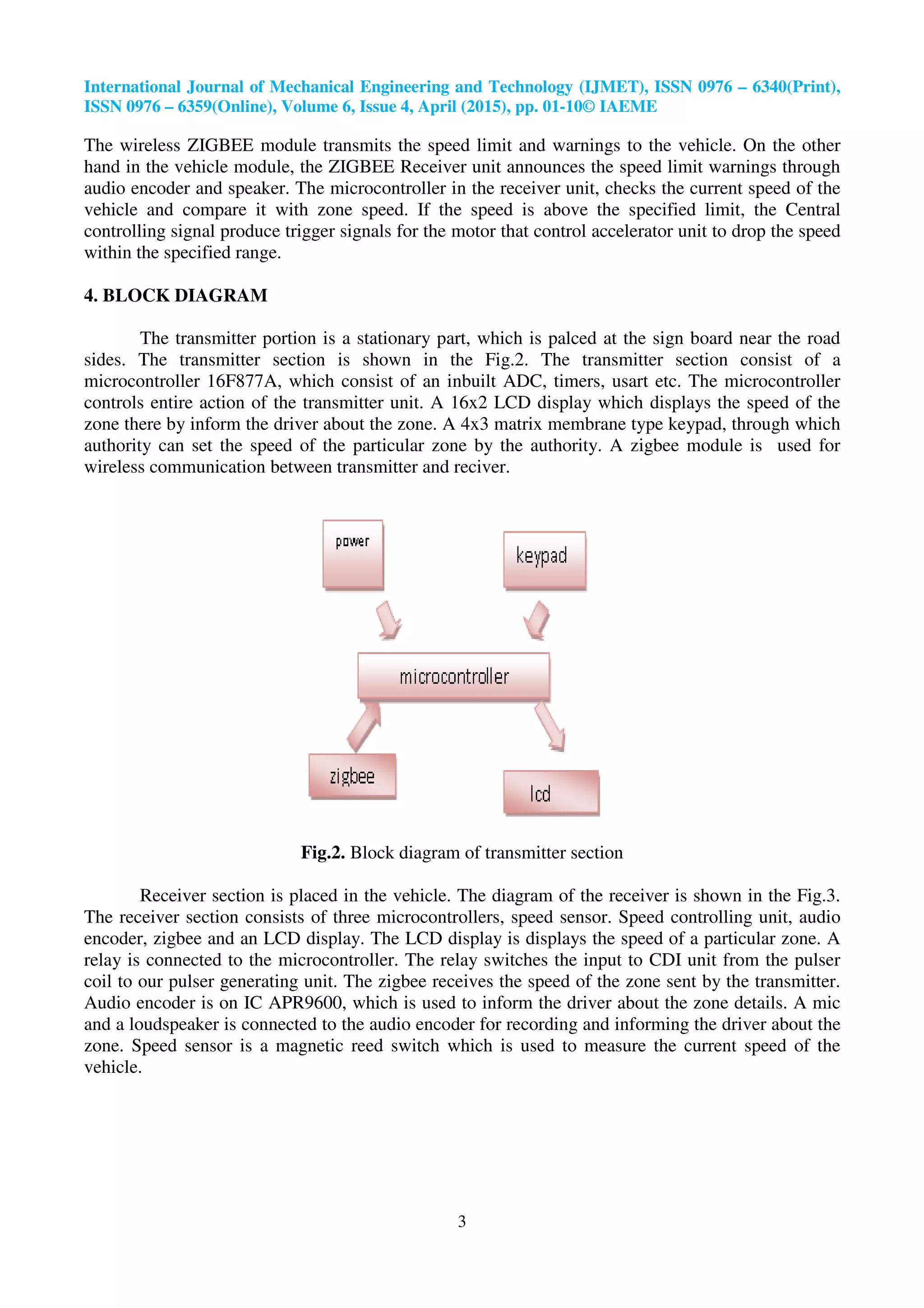
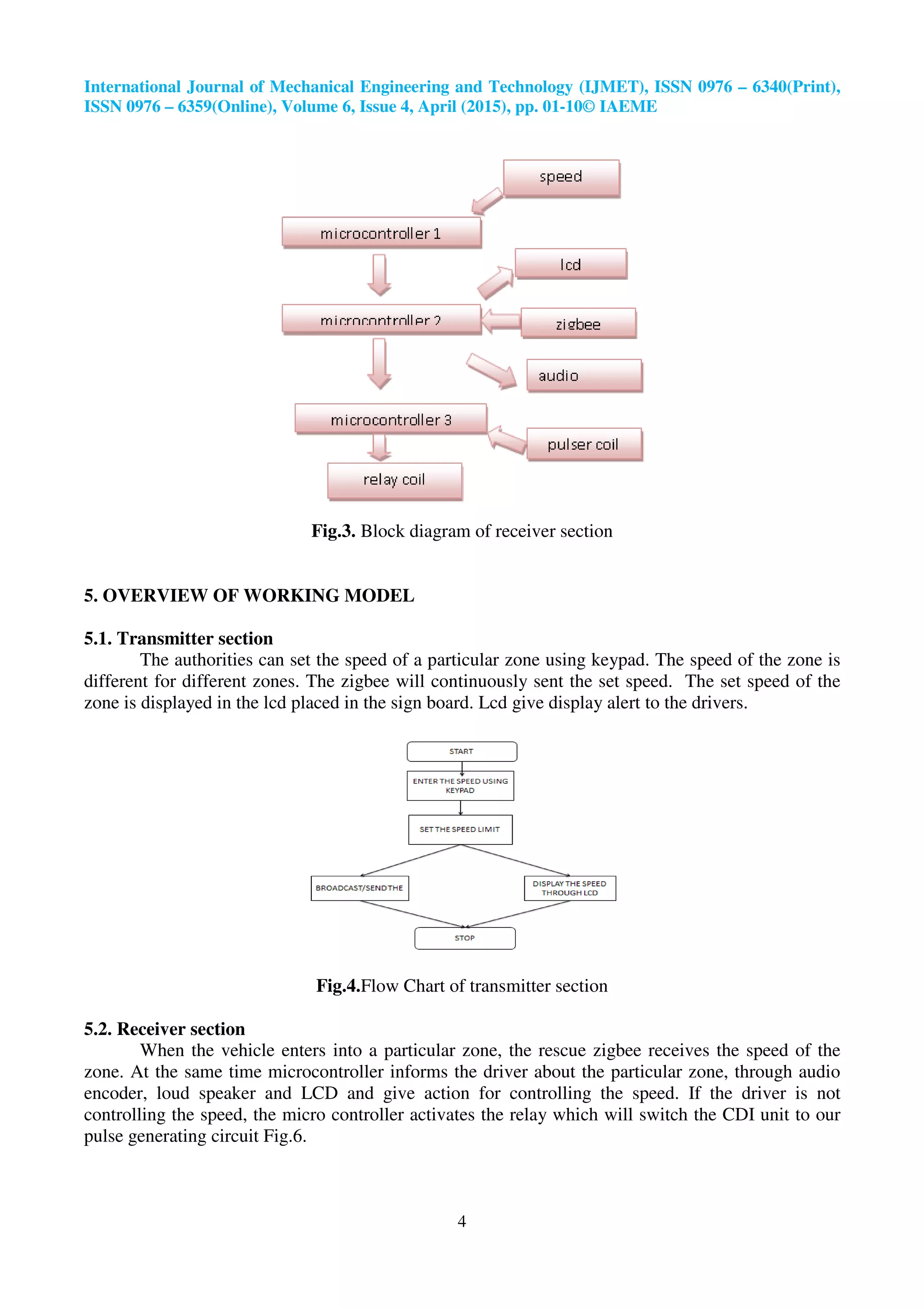
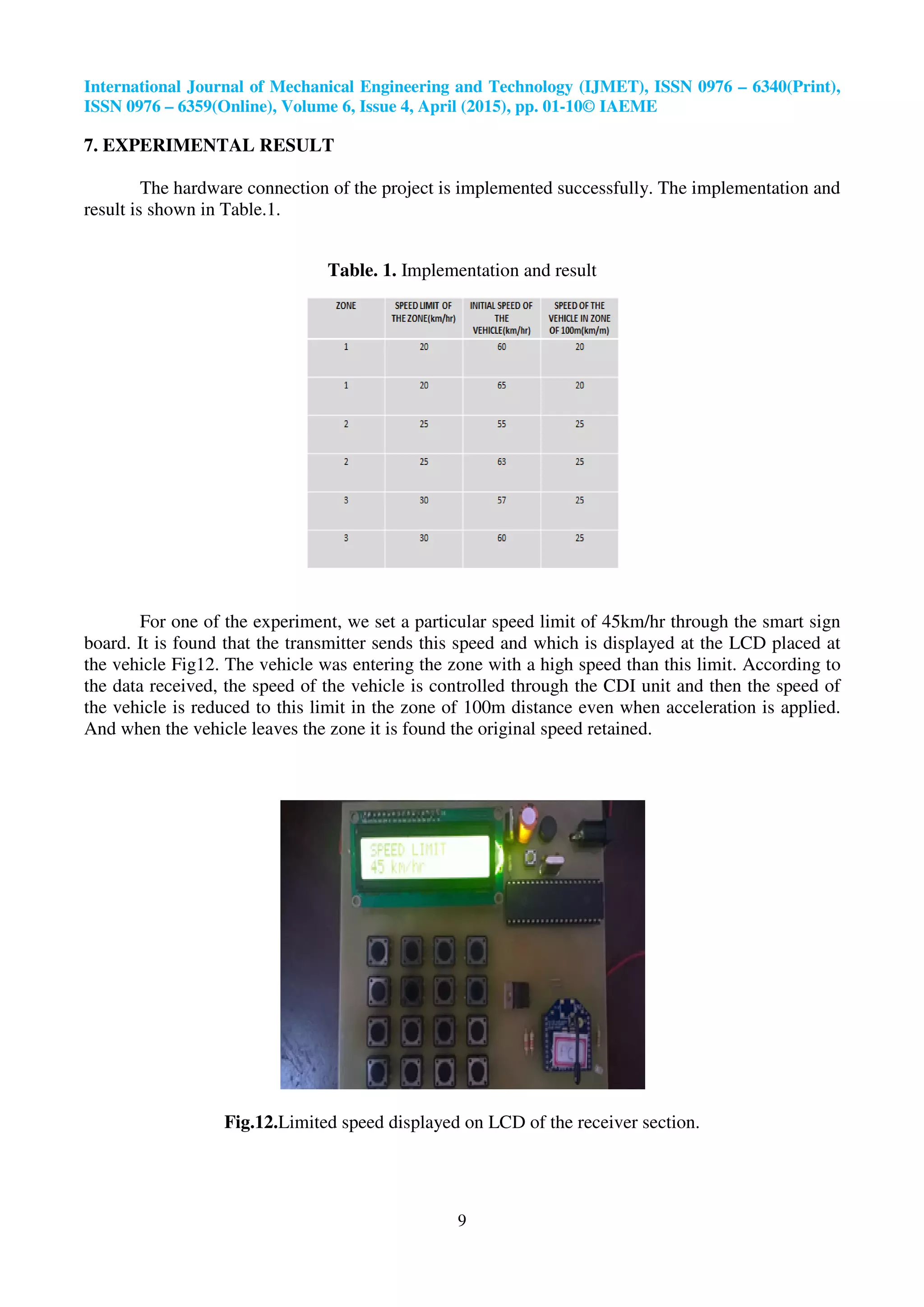

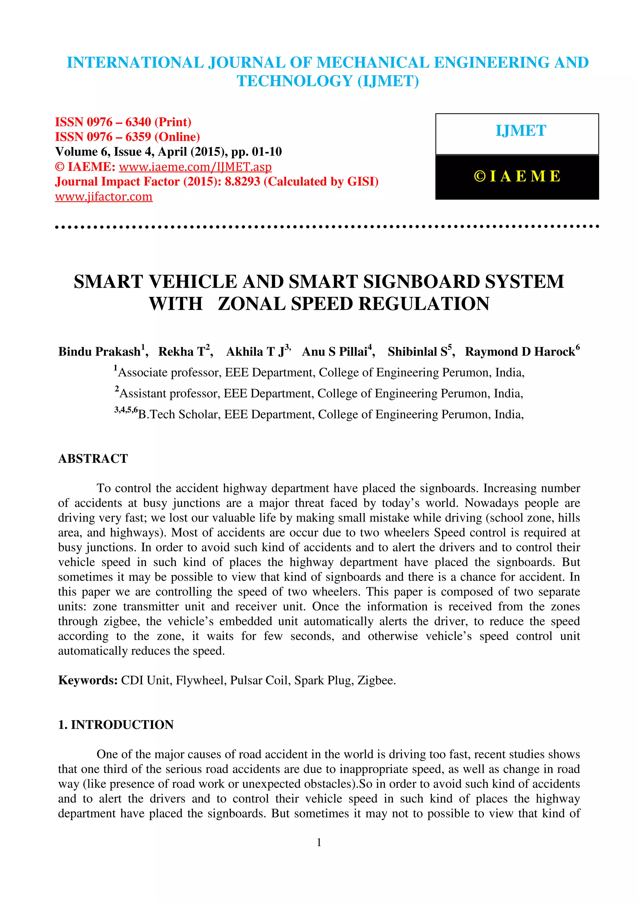
The document presents a smart vehicle and smart signboard system aimed at controlling the speed of two-wheelers to prevent accidents at busy junctions. It outlines a proposed system consisting of a zone transmitter and a receiver unit that communicates wirelessly using Zigbee technology, allowing for automatic speed regulation based on predefined zone limits. The system integrates a microcontroller for monitoring vehicle speed and issuing alerts, thereby enhancing road safety.