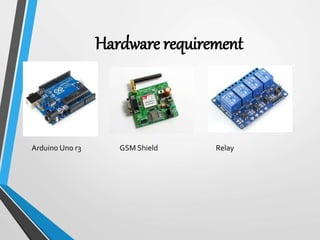
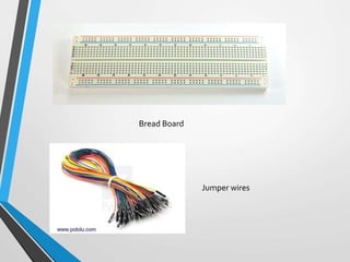
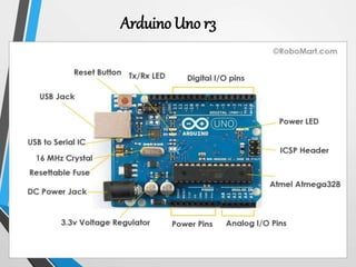
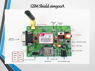
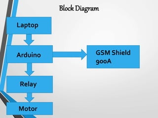
IOT and GSM Based Water Pump
Control
Submitted by
Chetana Chaudhary
INTRODUCTION:-
• The main aim of this project is to turn on and off water pump
from anywhere using mobile phone.
• Now a day’s most of the farmers use water from the wells and
underground water resources for their farms. And for this
they need water pumps.
• Using Arduino and GSM Shield we are implementing this
project.
• The purpose of this is to help the farmer to turn on or turn off
the motor. By using this farmer is able to operate the motor
from anywhere using mobile phone.
Software Requirement:-
Arduino IDE
Language used:-
Embedded C
C++
Hardware requirement
Arduino Uno r3 GSM Shield Relay
Bread Board
Jumper wires
Arduino Uno r3
• Arduino is an open source computer hardware and
software company, project, and user community that
designs and manufactures single-board
microcontrollers and microcontroller kits for building
digital devices and interactive objects that can sense
and control objects in the physical world.
• Arduino board designs use a variety of microprocessors
and controllers. The boards are equipped with sets of
digital and analog input/output (I/O) pins that may be
interfaced to various expansion boards (shields) and
other circuits.
Features of the Arduino UNO r3:
• Microcontroller: ATmega328
• OperatingVoltage: 5V
• InputVoltage (recommended): 7-12V
• InputVoltage (limits): 6-20V
• Digital I/O Pins: 14 (of which 6 provide PWM output)
• Analog Input Pins: 6
• DC Current per I/O Pin: 40 mA
• DC Current for 3.3V Pin: 50 mA
• Flash Memory: 32 KB of which 0.5 KB used by bootloader
• SRAM: 2 KB (ATmega328)
• EEPROM: 1 KB (ATmega328)
• Clock Speed: 16 MHz
GSM Shield sim900A
Specifications: GSM SIM900A USB SHIELD
• GSM/GPRS Module: SIMCOM SIM900A
• On board Interfaces
• USB (usb to serial using CP2102)
• RS232 with MAX232
• TTL pin breakout (RXD,TXD,GND)
General Feature
• Dual-Band 900/ 1800 MHz
•GPRS multi-slot class 10/8
•GPRS mobile station class B
•Compliant to GSM phase 2/2+
– Class 4 (2W @900 MHz)
– Class 1 (1W @ 1800MHz)
•SAIC (Single Antenna Interference Cancellation) support
•Dimensions: 24* 24 * 3 mm
•Weight: 3.4g
•Control via AT commands (GSM 07.07 ,07.05 and SIMCOM
enhanced AT Commands)
•SIM application toolkit
•Supply voltage range : 3.2 ... 4.8V
•Low power consumption: 1.0mA(sleep mode&BS -PA-
MFRMS=9 )
•Operation temperature: -40°C to +85 °C
RELAY:-
• A relay is an electrically operated switch. Current flowing
through the coil of the relay creates a magnetic field which
attracts a lever and changes the switch contacts.The coil
current can be on or off so relays have two switch positions
and they are double throw (changeover) switches.
Bread Board
• A breadboard is a solderless device for temporary
prototype with electronics and test circuit designs.
• Most electronic components in electronic circuits can be
interconnected by inserting their leads or terminals into
the holes and then making connections through wires
where appropriate.
• The breadboard has strips of metal underneath the board
and connect the holes on the top of the board.
• The top and bottom rows of holes are connected
horizontally and split in the middle while the remaining
holes are connected vertically.
Block Diagram
Laptop
Relay
GSM Shield
900A
Arduino
Motor
Future Scope :-
• Instead of GSM making use of GPRS and
controlling those appliances through internet.
• Instead of switching of the water pump when
single phase is present , convert the single phase
power supply to three phase power supply.
Thank you!!!

Smart agriculture system using IOT

  • 1.
    IOT and GSMBased Water Pump Control Submitted by Chetana Chaudhary
  • 2.
    INTRODUCTION:- • The mainaim of this project is to turn on and off water pump from anywhere using mobile phone. • Now a day’s most of the farmers use water from the wells and underground water resources for their farms. And for this they need water pumps. • Using Arduino and GSM Shield we are implementing this project. • The purpose of this is to help the farmer to turn on or turn off the motor. By using this farmer is able to operate the motor from anywhere using mobile phone.
  • 3.
  • 4.
  • 5.
  • 6.
  • 7.
    • Arduino isan open source computer hardware and software company, project, and user community that designs and manufactures single-board microcontrollers and microcontroller kits for building digital devices and interactive objects that can sense and control objects in the physical world. • Arduino board designs use a variety of microprocessors and controllers. The boards are equipped with sets of digital and analog input/output (I/O) pins that may be interfaced to various expansion boards (shields) and other circuits.
  • 8.
    Features of theArduino UNO r3: • Microcontroller: ATmega328 • OperatingVoltage: 5V • InputVoltage (recommended): 7-12V • InputVoltage (limits): 6-20V • Digital I/O Pins: 14 (of which 6 provide PWM output) • Analog Input Pins: 6 • DC Current per I/O Pin: 40 mA • DC Current for 3.3V Pin: 50 mA • Flash Memory: 32 KB of which 0.5 KB used by bootloader • SRAM: 2 KB (ATmega328) • EEPROM: 1 KB (ATmega328) • Clock Speed: 16 MHz
  • 9.
  • 10.
    Specifications: GSM SIM900AUSB SHIELD • GSM/GPRS Module: SIMCOM SIM900A • On board Interfaces • USB (usb to serial using CP2102) • RS232 with MAX232 • TTL pin breakout (RXD,TXD,GND)
  • 11.
    General Feature • Dual-Band900/ 1800 MHz •GPRS multi-slot class 10/8 •GPRS mobile station class B •Compliant to GSM phase 2/2+ – Class 4 (2W @900 MHz) – Class 1 (1W @ 1800MHz) •SAIC (Single Antenna Interference Cancellation) support •Dimensions: 24* 24 * 3 mm •Weight: 3.4g •Control via AT commands (GSM 07.07 ,07.05 and SIMCOM enhanced AT Commands) •SIM application toolkit •Supply voltage range : 3.2 ... 4.8V •Low power consumption: 1.0mA(sleep mode&BS -PA- MFRMS=9 ) •Operation temperature: -40°C to +85 °C
  • 12.
    RELAY:- • A relayis an electrically operated switch. Current flowing through the coil of the relay creates a magnetic field which attracts a lever and changes the switch contacts.The coil current can be on or off so relays have two switch positions and they are double throw (changeover) switches.
  • 13.
    Bread Board • Abreadboard is a solderless device for temporary prototype with electronics and test circuit designs. • Most electronic components in electronic circuits can be interconnected by inserting their leads or terminals into the holes and then making connections through wires where appropriate. • The breadboard has strips of metal underneath the board and connect the holes on the top of the board. • The top and bottom rows of holes are connected horizontally and split in the middle while the remaining holes are connected vertically.
  • 15.
  • 16.
    Future Scope :- •Instead of GSM making use of GPRS and controlling those appliances through internet. • Instead of switching of the water pump when single phase is present , convert the single phase power supply to three phase power supply.
  • 17.