SlideShare a Scribd company logo
Power Electronics System
• Convert electric power from one form to
another using power electronics devices.
• Power Electronics system block diagram:
1
EPPB2034 prepared by Toh Chuen Ling
Converter Classification
2
EPPB2034 prepared by Toh Chuen Ling
• AC-DC (Rectifier)
• DC-AC (Inverter)
• DC-DC (Chopper/Booster)
• AC-AC (Cyclo-converter)
Applications
3
Adjustable frequency
EPPB2034 prepared by Toh Chuen Ling
Application:
• Wind turbines generate variable voltage in
magnitude and frequency due to the fact that
wind speed and power is not constant over a day.
In order to transfer power from the generator into
a grid, power converters are required to adjust the
frequency and magnitude.
4
EPPB2034 prepared by Toh Chuen Ling
Interdisciplinary Nature of Power Electronics
5
Power Electronics Concepts
6
?
EPPB2034 prepared by Toh Chuen Ling
Copyright © 2011 by McGraw Hill.
Solutions:
1. Voltage divider
2. A switch circuit
Low-Pass Filter + Switch
control
7
EPPB2034 prepared by Toh Chuen Ling
Copyright © 2011 by McGraw Hill.
Devices Power Diodes
(Uncontrolled)
Thyristors
(Semi-controlled)
Power Transistors
(Fully controlled)
Types • General purpose
• High speed (Fast
Recovery)
• Schottky
• Silicon Carbine (SiC)
• Silicon-controlled
Rectifier (SCR)
• Power BJT
• Power MOSFET
• IGBT
Power Semiconductor Devices
8
EPPB2034 prepared by Toh Chuen Ling
Power Diode
• The ON and OFF states are determined by
voltages and currents in the circuit.
9
Conduction i-v Ideal case diode
Forward-biased
(ON)
Current id positive Short circuit
Reverse-biased
(OFF)
Voltage vd is
negative
Open circuit
EPPB2034 prepared by Toh Chuen Ling
Copyright © 2011 by McGraw Hill.
Reverse Recovery
i
t2
t1
t
ON
OFF
trr = (t2 – t1 )
The current is decreases and momentarily becomes negative before
becoming zero.
The time trr is usually less than 1 µs.
10
EPPB2034 prepared by Toh Chuen Ling
EPPB2034 prepared by Toh Chuen Ling 11
Thyristors (SCR)
Copyright © 2011 by McGraw Hill.
• Gate Turn-Off Thyristor (GTO)
– Behave like normal thyristor, but can be turned off using gate signal
– However turning off is difficult. Need very large reverse gate current
(normally 1/3 of the on-state anode current).
• Triac
– Capable of conducting current in either direction
– Equivalent to two antiparallel SCRs
• MOS-Controlled thyristor (MCT)
– voltage controlled device
– Low voltage drop in the on state at relatively
high currents
– Faster switching speed in s range.
12
Thyristors
EPPB2034 prepared by Toh Chuen Ling
* A thyristor is turned on by
applying a gate current thru gate
node while its in the forward
biased state. The device will remain
on so long as the current flows
thru the thytristor is positive
regardless of the gate current.
Power Transistors: Metal-Oxide-Semiconductor
Field Effect Transistor
– Voltage controlled device
– Supply a sufficient vGS to trigger ON the device.
(vGS  20V)
– ON state: voltage drop across Drain-Source terminal, vDS.
[RDS(ON)  m]
– Switching frequency in MHz range.
EPPB2034 prepared by Toh Chuen Ling 13
Copyright © 2011 by McGraw Hill.
– Current controlled device
– Supply a sufficient iB to trigger ON the device. (iB must be
supply continuously to keep the BJT ON)
– ON state: voltage drop across Collector-Emitter terminal,
vCE  1-2V
– Rarely used in new applications, being surpassed by
MOSFET and IGBT.
Power Transistor: Bipolar Junction Transistor
EPPB2034 prepared by Toh Chuen Ling 14
Copyright © 2011 by McGraw Hill.
Power Transistor:
Insulated Gate Bipolar Transistor
• Combine the advantages of MOSFET, BJT, and
GTO.
– Small amount of energy to switch on the device,
– Small on-state voltage drop, VCE(ON) is 2-3V.
– Block negative voltages
• Medium switching speed
EPPB2034 prepared by Toh Chuen Ling 15
Summary of Device Capabilities
EPPB2034 prepared by Toh Chuen Ling 19
• Power usually refers to average power,
which is the time average of periodic
instantaneous power:
• Instantaneous Power, p(t) = v(t)i(t)
– Positive p(t): absorbing power
– Negative p(t): supplying power
Power
EPPB2034 prepared by Toh Chuen Ling 17
Copyright © 2011 by McGraw Hill
Instantaneous Power,
p(t) = v(t)i(t)
EPPB2034 prepared by Toh Chuen Ling 18
Copyright © 2011 by McGraw Hill
Effective Value/Root-Mean-Square (rms) value
• The effective or rms voltage:
• The effective or rms current:
EPPB2034 prepared by Toh Chuen Ling 19
Copyright © 2011 by McGraw Hill
Distortion
Component
RMS value of non-sinusoidal waveforms
EPPB2034 prepared by Toh Chuen Ling 20
 








1
2
,
2
,
1
2
,
0
2
0
0
1
n
rms
n
rms
rms
T
t
t
rms
I
I
I
dt
t
i
T
I
       





1
1
0
n
n t
i
t
i
t
i
t
i
Copyright © 2011 by McGraw Hill
Apparent Power and Power Factor
Apparent Power S:
• Apparent power is the product of rms
voltage and rms current magnitudes:
Power Factor:
– How effectively the load draws the real power:
EPPB2034 prepared by Toh Chuen Ling 21
Copyright © 2011 by McGraw Hill
Power Computation for Non-Sinusoidal
Periodic Waveforms
EPPB2034 prepared by Toh Chuen Ling 22
Copyright © 2011 by McGraw Hill
Fourier Analysis of Repetitive Waveforms
• A non-sinusoidal waveform f(t) repeating with
an angular frequency  can be expressed as
23
 
 
1
0
1
( )
1
cos( ) sin( )
2
o h
h
h h
h
f t F f t
a a h t b h t
 




 
  


EPPB2034 prepared by Toh Chuen Ling
Fourier Series Analysis
• The instantaneous output voltage and load current
can be expressed in Fourier series, due to it
harmonics contain.
• Fourier Series
   
 











1
0
1
0
sin
cos
)
(
)
(
n
n
n
n
n
t
n
b
t
n
a
F
t
f
F
t
f


 
     
     
t
d
t
n
t
f
b
t
d
t
n
t
f
a
dt
t
f
T
F
n
n
T














2
0
2
0
0
0
sin
1
cos
1
1
24
EPPB2034 prepared by Toh Chuen Ling

More Related Content

Similar to Intoduction To Electronics (Diodes & Rec)

Selection of Power Semiconductor Switches in M.H.B.R.I. Fitted Induction Heat...
Selection of Power Semiconductor Switches in M.H.B.R.I. Fitted Induction Heat...Selection of Power Semiconductor Switches in M.H.B.R.I. Fitted Induction Heat...
Selection of Power Semiconductor Switches in M.H.B.R.I. Fitted Induction Heat...
IAES-IJPEDS
 
Ppt1
Ppt1Ppt1
Ppt1
v0run
 
MICROCONTROLLER BASED HARMONIC RESTRAINT DIFFERENTIAL PROTECTION OF POWER TRA...
MICROCONTROLLER BASED HARMONIC RESTRAINT DIFFERENTIAL PROTECTION OF POWER TRA...MICROCONTROLLER BASED HARMONIC RESTRAINT DIFFERENTIAL PROTECTION OF POWER TRA...
MICROCONTROLLER BASED HARMONIC RESTRAINT DIFFERENTIAL PROTECTION OF POWER TRA...
Netram Meena
 

Similar to Intoduction To Electronics (Diodes & Rec) (20)

Mod_1_Transformers1.ppt
Mod_1_Transformers1.pptMod_1_Transformers1.ppt
Mod_1_Transformers1.ppt
 
Mod_1_Transformers1.ppt
Mod_1_Transformers1.pptMod_1_Transformers1.ppt
Mod_1_Transformers1.ppt
 
Maximum power point tracking converter
Maximum power point tracking converterMaximum power point tracking converter
Maximum power point tracking converter
 
Chapter 1 part II.ppt
Chapter 1 part II.pptChapter 1 part II.ppt
Chapter 1 part II.ppt
 
Chapter 1 - Polyphase Circuit Analysis.pptx
Chapter 1 - Polyphase Circuit Analysis.pptxChapter 1 - Polyphase Circuit Analysis.pptx
Chapter 1 - Polyphase Circuit Analysis.pptx
 
Presentation 12v dc to 230v ac 100 wat invertor
Presentation 12v dc to 230v ac 100 wat invertorPresentation 12v dc to 230v ac 100 wat invertor
Presentation 12v dc to 230v ac 100 wat invertor
 
Electrodynamometer type instrument.pptx
Electrodynamometer type instrument.pptxElectrodynamometer type instrument.pptx
Electrodynamometer type instrument.pptx
 
Selection of Power Semiconductor Switches in M.H.B.R.I. Fitted Induction Heat...
Selection of Power Semiconductor Switches in M.H.B.R.I. Fitted Induction Heat...Selection of Power Semiconductor Switches in M.H.B.R.I. Fitted Induction Heat...
Selection of Power Semiconductor Switches in M.H.B.R.I. Fitted Induction Heat...
 
PED drivers t5656979089897877ghvvnvgcxxn
PED drivers t5656979089897877ghvvnvgcxxnPED drivers t5656979089897877ghvvnvgcxxn
PED drivers t5656979089897877ghvvnvgcxxn
 
Ppt1
Ppt1Ppt1
Ppt1
 
circuit diagram.pptx
circuit diagram.pptxcircuit diagram.pptx
circuit diagram.pptx
 
Transducers.pptx
Transducers.pptxTransducers.pptx
Transducers.pptx
 
MICROCONTROLLER BASED HARMONIC RESTRAINT DIFFERENTIAL PROTECTION OF POWER TRA...
MICROCONTROLLER BASED HARMONIC RESTRAINT DIFFERENTIAL PROTECTION OF POWER TRA...MICROCONTROLLER BASED HARMONIC RESTRAINT DIFFERENTIAL PROTECTION OF POWER TRA...
MICROCONTROLLER BASED HARMONIC RESTRAINT DIFFERENTIAL PROTECTION OF POWER TRA...
 
SPEED CONTROL OF DC MOTOR USING DC/DC BOOST CONVERTER
SPEED CONTROL OF DC MOTOR USING DC/DC BOOST CONVERTERSPEED CONTROL OF DC MOTOR USING DC/DC BOOST CONVERTER
SPEED CONTROL OF DC MOTOR USING DC/DC BOOST CONVERTER
 
various_electrical_converting(konverter listrik)
various_electrical_converting(konverter listrik)various_electrical_converting(konverter listrik)
various_electrical_converting(konverter listrik)
 
Summer Tranning priyanshu tiwari by aditya.pptx
Summer Tranning priyanshu tiwari by aditya.pptxSummer Tranning priyanshu tiwari by aditya.pptx
Summer Tranning priyanshu tiwari by aditya.pptx
 
Piezoelectric Energy Harvesting.
Piezoelectric Energy Harvesting.Piezoelectric Energy Harvesting.
Piezoelectric Energy Harvesting.
 
Starting of fluorescent tube light by using inverter circuit instead of choke...
Starting of fluorescent tube light by using inverter circuit instead of choke...Starting of fluorescent tube light by using inverter circuit instead of choke...
Starting of fluorescent tube light by using inverter circuit instead of choke...
 
Modeling Of Converter “Single Phase to Three Phase by Using Single Phase Sup...
Modeling Of Converter “Single Phase to Three Phase by Using Single Phase  Sup...Modeling Of Converter “Single Phase to Three Phase by Using Single Phase  Sup...
Modeling Of Converter “Single Phase to Three Phase by Using Single Phase Sup...
 
IJSRED-V2I2P61
IJSRED-V2I2P61IJSRED-V2I2P61
IJSRED-V2I2P61
 

Recently uploaded

Online blood donation management system project.pdf
Online blood donation management system project.pdfOnline blood donation management system project.pdf
Online blood donation management system project.pdf
Kamal Acharya
 
Laundry management system project report.pdf
Laundry management system project report.pdfLaundry management system project report.pdf
Laundry management system project report.pdf
Kamal Acharya
 

Recently uploaded (20)

Pharmacy management system project report..pdf
Pharmacy management system project report..pdfPharmacy management system project report..pdf
Pharmacy management system project report..pdf
 
Introduction to Machine Learning Unit-4 Notes for II-II Mechanical Engineering
Introduction to Machine Learning Unit-4 Notes for II-II Mechanical EngineeringIntroduction to Machine Learning Unit-4 Notes for II-II Mechanical Engineering
Introduction to Machine Learning Unit-4 Notes for II-II Mechanical Engineering
 
An improvement in the safety of big data using blockchain technology
An improvement in the safety of big data using blockchain technologyAn improvement in the safety of big data using blockchain technology
An improvement in the safety of big data using blockchain technology
 
İTÜ CAD and Reverse Engineering Workshop
İTÜ CAD and Reverse Engineering WorkshopİTÜ CAD and Reverse Engineering Workshop
İTÜ CAD and Reverse Engineering Workshop
 
Peek implant persentation - Copy (1).pdf
Peek implant persentation - Copy (1).pdfPeek implant persentation - Copy (1).pdf
Peek implant persentation - Copy (1).pdf
 
retail automation billing system ppt.pptx
retail automation billing system ppt.pptxretail automation billing system ppt.pptx
retail automation billing system ppt.pptx
 
Natalia Rutkowska - BIM School Course in Kraków
Natalia Rutkowska - BIM School Course in KrakówNatalia Rutkowska - BIM School Course in Kraków
Natalia Rutkowska - BIM School Course in Kraków
 
Online blood donation management system project.pdf
Online blood donation management system project.pdfOnline blood donation management system project.pdf
Online blood donation management system project.pdf
 
Attraction and Repulsion type Moving Iron Instruments.pptx
Attraction and Repulsion type Moving Iron Instruments.pptxAttraction and Repulsion type Moving Iron Instruments.pptx
Attraction and Repulsion type Moving Iron Instruments.pptx
 
Laundry management system project report.pdf
Laundry management system project report.pdfLaundry management system project report.pdf
Laundry management system project report.pdf
 
RM&IPR M5 notes.pdfResearch Methodolgy & Intellectual Property Rights Series 5
RM&IPR M5 notes.pdfResearch Methodolgy & Intellectual Property Rights Series 5RM&IPR M5 notes.pdfResearch Methodolgy & Intellectual Property Rights Series 5
RM&IPR M5 notes.pdfResearch Methodolgy & Intellectual Property Rights Series 5
 
Software Engineering - Modelling Concepts + Class Modelling + Building the An...
Software Engineering - Modelling Concepts + Class Modelling + Building the An...Software Engineering - Modelling Concepts + Class Modelling + Building the An...
Software Engineering - Modelling Concepts + Class Modelling + Building the An...
 
Introduction to Machine Learning Unit-5 Notes for II-II Mechanical Engineering
Introduction to Machine Learning Unit-5 Notes for II-II Mechanical EngineeringIntroduction to Machine Learning Unit-5 Notes for II-II Mechanical Engineering
Introduction to Machine Learning Unit-5 Notes for II-II Mechanical Engineering
 
"United Nations Park" Site Visit Report.
"United Nations Park" Site  Visit Report."United Nations Park" Site  Visit Report.
"United Nations Park" Site Visit Report.
 
The battle for RAG, explore the pros and cons of using KnowledgeGraphs and Ve...
The battle for RAG, explore the pros and cons of using KnowledgeGraphs and Ve...The battle for RAG, explore the pros and cons of using KnowledgeGraphs and Ve...
The battle for RAG, explore the pros and cons of using KnowledgeGraphs and Ve...
 
Construction method of steel structure space frame .pptx
Construction method of steel structure space frame .pptxConstruction method of steel structure space frame .pptx
Construction method of steel structure space frame .pptx
 
Quality defects in TMT Bars, Possible causes and Potential Solutions.
Quality defects in TMT Bars, Possible causes and Potential Solutions.Quality defects in TMT Bars, Possible causes and Potential Solutions.
Quality defects in TMT Bars, Possible causes and Potential Solutions.
 
Online book store management system project.pdf
Online book store management system project.pdfOnline book store management system project.pdf
Online book store management system project.pdf
 
Research Methodolgy & Intellectual Property Rights Series 2
Research Methodolgy & Intellectual Property Rights Series 2Research Methodolgy & Intellectual Property Rights Series 2
Research Methodolgy & Intellectual Property Rights Series 2
 
1. Henrich Triangle Safety and Fire Presentation
1. Henrich Triangle Safety and Fire Presentation1. Henrich Triangle Safety and Fire Presentation
1. Henrich Triangle Safety and Fire Presentation
 

Intoduction To Electronics (Diodes & Rec)

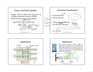
  • 1. Power Electronics System • Convert electric power from one form to another using power electronics devices. • Power Electronics system block diagram: 1 EPPB2034 prepared by Toh Chuen Ling Converter Classification 2 EPPB2034 prepared by Toh Chuen Ling • AC-DC (Rectifier) • DC-AC (Inverter) • DC-DC (Chopper/Booster) • AC-AC (Cyclo-converter) Applications 3 Adjustable frequency EPPB2034 prepared by Toh Chuen Ling Application: • Wind turbines generate variable voltage in magnitude and frequency due to the fact that wind speed and power is not constant over a day. In order to transfer power from the generator into a grid, power converters are required to adjust the frequency and magnitude. 4 EPPB2034 prepared by Toh Chuen Ling
  • 2. EPPB2034 prepared by Toh Chuen Ling Interdisciplinary Nature of Power Electronics 5 Power Electronics Concepts 6 ? EPPB2034 prepared by Toh Chuen Ling Copyright © 2011 by McGraw Hill. Solutions: 1. Voltage divider 2. A switch circuit Low-Pass Filter + Switch control 7 EPPB2034 prepared by Toh Chuen Ling Copyright © 2011 by McGraw Hill. Devices Power Diodes (Uncontrolled) Thyristors (Semi-controlled) Power Transistors (Fully controlled) Types • General purpose • High speed (Fast Recovery) • Schottky • Silicon Carbine (SiC) • Silicon-controlled Rectifier (SCR) • Power BJT • Power MOSFET • IGBT Power Semiconductor Devices 8 EPPB2034 prepared by Toh Chuen Ling
  • 3. Power Diode • The ON and OFF states are determined by voltages and currents in the circuit. 9 Conduction i-v Ideal case diode Forward-biased (ON) Current id positive Short circuit Reverse-biased (OFF) Voltage vd is negative Open circuit EPPB2034 prepared by Toh Chuen Ling Copyright © 2011 by McGraw Hill. Reverse Recovery i t2 t1 t ON OFF trr = (t2 – t1 ) The current is decreases and momentarily becomes negative before becoming zero. The time trr is usually less than 1 µs. 10 EPPB2034 prepared by Toh Chuen Ling EPPB2034 prepared by Toh Chuen Ling 11 Thyristors (SCR) Copyright © 2011 by McGraw Hill. • Gate Turn-Off Thyristor (GTO) – Behave like normal thyristor, but can be turned off using gate signal – However turning off is difficult. Need very large reverse gate current (normally 1/3 of the on-state anode current). • Triac – Capable of conducting current in either direction – Equivalent to two antiparallel SCRs • MOS-Controlled thyristor (MCT) – voltage controlled device – Low voltage drop in the on state at relatively high currents – Faster switching speed in s range. 12 Thyristors EPPB2034 prepared by Toh Chuen Ling * A thyristor is turned on by applying a gate current thru gate node while its in the forward biased state. The device will remain on so long as the current flows thru the thytristor is positive regardless of the gate current.
  • 4. Power Transistors: Metal-Oxide-Semiconductor Field Effect Transistor – Voltage controlled device – Supply a sufficient vGS to trigger ON the device. (vGS  20V) – ON state: voltage drop across Drain-Source terminal, vDS. [RDS(ON)  m] – Switching frequency in MHz range. EPPB2034 prepared by Toh Chuen Ling 13 Copyright © 2011 by McGraw Hill. – Current controlled device – Supply a sufficient iB to trigger ON the device. (iB must be supply continuously to keep the BJT ON) – ON state: voltage drop across Collector-Emitter terminal, vCE  1-2V – Rarely used in new applications, being surpassed by MOSFET and IGBT. Power Transistor: Bipolar Junction Transistor EPPB2034 prepared by Toh Chuen Ling 14 Copyright © 2011 by McGraw Hill. Power Transistor: Insulated Gate Bipolar Transistor • Combine the advantages of MOSFET, BJT, and GTO. – Small amount of energy to switch on the device, – Small on-state voltage drop, VCE(ON) is 2-3V. – Block negative voltages • Medium switching speed EPPB2034 prepared by Toh Chuen Ling 15 Summary of Device Capabilities EPPB2034 prepared by Toh Chuen Ling 19
  • 5. • Power usually refers to average power, which is the time average of periodic instantaneous power: • Instantaneous Power, p(t) = v(t)i(t) – Positive p(t): absorbing power – Negative p(t): supplying power Power EPPB2034 prepared by Toh Chuen Ling 17 Copyright © 2011 by McGraw Hill Instantaneous Power, p(t) = v(t)i(t) EPPB2034 prepared by Toh Chuen Ling 18 Copyright © 2011 by McGraw Hill Effective Value/Root-Mean-Square (rms) value • The effective or rms voltage: • The effective or rms current: EPPB2034 prepared by Toh Chuen Ling 19 Copyright © 2011 by McGraw Hill Distortion Component RMS value of non-sinusoidal waveforms EPPB2034 prepared by Toh Chuen Ling 20           1 2 , 2 , 1 2 , 0 2 0 0 1 n rms n rms rms T t t rms I I I dt t i T I              1 1 0 n n t i t i t i t i Copyright © 2011 by McGraw Hill
  • 6. Apparent Power and Power Factor Apparent Power S: • Apparent power is the product of rms voltage and rms current magnitudes: Power Factor: – How effectively the load draws the real power: EPPB2034 prepared by Toh Chuen Ling 21 Copyright © 2011 by McGraw Hill Power Computation for Non-Sinusoidal Periodic Waveforms EPPB2034 prepared by Toh Chuen Ling 22 Copyright © 2011 by McGraw Hill Fourier Analysis of Repetitive Waveforms • A non-sinusoidal waveform f(t) repeating with an angular frequency  can be expressed as 23     1 0 1 ( ) 1 cos( ) sin( ) 2 o h h h h h f t F f t a a h t b h t              EPPB2034 prepared by Toh Chuen Ling Fourier Series Analysis • The instantaneous output voltage and load current can be expressed in Fourier series, due to it harmonics contain. • Fourier Series                  1 0 1 0 sin cos ) ( ) ( n n n n n t n b t n a F t f F t f                 t d t n t f b t d t n t f a dt t f T F n n T               2 0 2 0 0 0 sin 1 cos 1 1 24 EPPB2034 prepared by Toh Chuen Ling