Downloaded 11 times


![Siemens ST PCS 7 · April 2005
12/2 Introduction
12/3 Centralized I/O
12/3 Central I/O modules
12/4 Expansion units for central I/O
12/5 ET 200M distributed I/O
12/5 Introduction
12/6 Power supply
12/6 Interface modules
12/7 Accessories
12/8 Bundles
12/9 DI - digital input modules
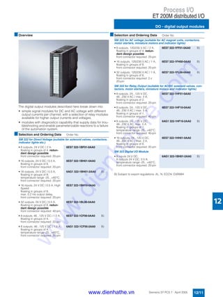
12/11 DO - digital output modules
12/13 AI - analog input modules
12/15 AO - analog output modules
12/16 Ex modules [EEi xb]
12/17 Ex modules with HART
12/18 F modules
12/20 Controller modules
12/21 Counter modules
12/22 ET 200iSP distributed I/O
12/22 Introduction
12/24 ET 200iSP power supply unit
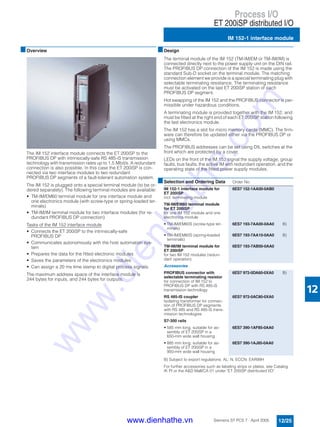
12/25 IM 152-1 interface module
12/26 Electronics modules
12/28 RS485-iS coupler
12/29 Stainless steel wall housing
12/30 ET 200S distributed I/O
12/30 Introduction
12/32 Terminal modules
12/34 Interface modules
12/34 Power modules
12/36 Digital electronics modules
12/38 Analog electronics modules
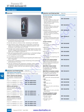
12/40 Motor starters
12/42 SIGUARD Safety Integrated
Process I/O
www.dienhathe.vn
www.dienhathe.com](https://image.slidesharecdn.com/siemenssimaticsimaticpcs7-2-180725030538/85/Siemens-simatic-simatic-pcs-7-2-153-320.jpg)
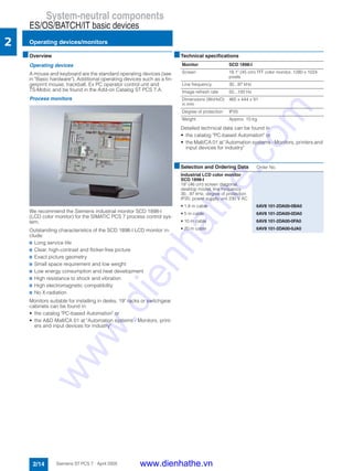
![Process I/O
Introduction
12/2 Siemens ST PCS 7 · April 2005
12
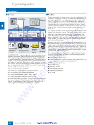
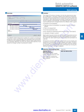
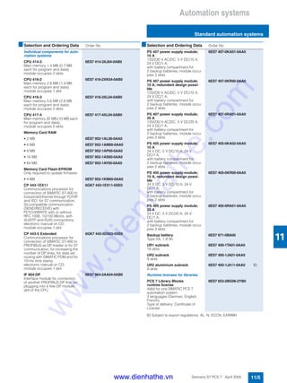
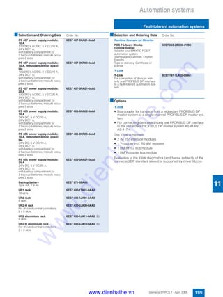
■Overview
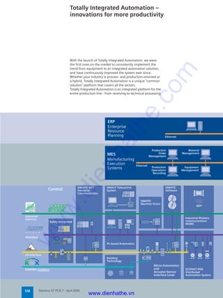
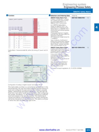
The SIMATIC PCS 7 process control system offers various pos-
sibilities for connecting I/O devices and for detecting and emit-
ting process signals through sensors and actuators:
• Analog and digital I/O modules of the SIMATIC S7-400 oper-
ated centrally in the automation system
• Distributed ET 200M, ET 200S, ET 200iSP I/O systems with an
extensive range of cost-effective signal and function modules,
connected through PROFIBUS DP to the automation system
(AS)
• Direct AS connection of intelligent, distributed field/process
devices and operator terminals through PROFIBUS DP/PA (re-
dundant or in hazardous zones 0, 1 or 2 also possible)
Signal groups of the SIMATIC S7-400 can be operated centrally
in the automation system and are mainly used in small applica-
tions or systems of limited distributed expansion.
Characteristics such as
• modularity and consistency,
• flexible adaptability to the plant structure,
• minimum cabling and engineering requirements,
• low commissioning, servicing and lifecycle costs and a
• wide range of technical options
are the main reasons why distributed process peripherals are
now predominant: ET 200 remote I/Os in conjunction with classi-
cal field/process devices and HART field devices or intelligent
field/process devices directly on PROFIBUS.
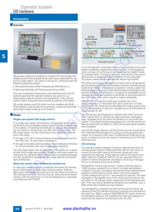
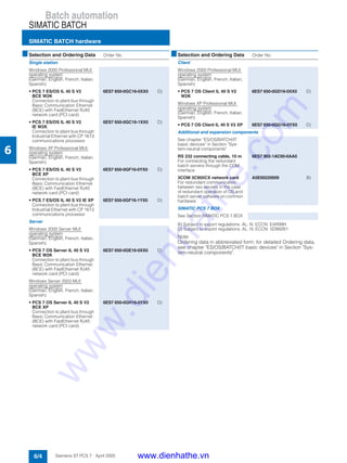
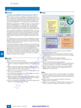
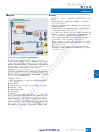
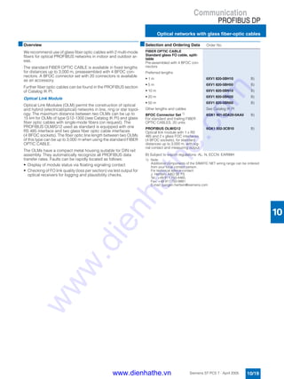
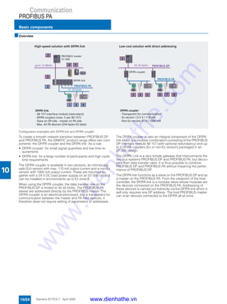
■Design
Integration of I/O modules in the hazardous area
The picture shows the various possibilities for integrating I/O
modules in the hazardous area:
Ex I/O modules from the ET 200M range
The ET 200M can be run in Ex zone 2. The actuators/sensors
can be positioned in Ex zone 1 when suitable Ex I/O modules are
used. Hot swapping of I/O modules within Ex zone 2 is allowed
with the right permit (e.g. fire certificate). FM approvals: Class I,
Division 2 and Class I, Zone 2.
Field devices with PROFIBUS PA capability
Using PROFIBUS it is possible to integrate field/process devices
directly in Ex zone 1 or 2, and sensors/actuators can also be in-
tegrated in zone 0. FM approvals: Class I, Division 1 and Class I,
Zone 0.
Integration of actuators/sensors using ET 200iSP
The ET 200iSP appropriate for gaseous and dusty atmospheres
can be installed, according to CENELEC II 2 G (1) GD Eex d e
[ib/ia] IIC T4 directly in the Ex zones 1, 2, 21 or 22 as well as in
non-hazardous areas. The intrinsically-safe sensors, actuators
and HART field devices can also be located in zone 0 or 20 if
necessary.
Intrinsically-safe operator control unit
An intrinsically safe PC operator control unit can be used in haz-
ardous areas, zone 1 or 2, if required. For further details on this
operator control unit, see Catalog "Add Ons for the SIMATIC
PCS 7 Process Control System".
■Function
Possible online modifications among the process I/Os
ET 200M • Adding of ET 200M stations
• Adding of I/O modules for the station
• Reparameterization of I/O modules
• Parameterization of connected HART field devic-
es with SIMATIC PDM
ET 200iSP • Adding of ET 200iSP stations
• Adding of modules for the station
• Reparameterization of modules
ET 200S • Adding of ET 200S stations
PROFIBUS DP,
PROFIBUS PA
• Adding of PROFIBUS DP stations
• Adding of DP/PA links and field devices
• Parameterization of field devices with
SIMATIC PDM
www.dienhathe.vn
www.dienhathe.com](https://image.slidesharecdn.com/siemenssimaticsimaticpcs7-2-180725030538/85/Siemens-simatic-simatic-pcs-7-2-154-320.jpg)

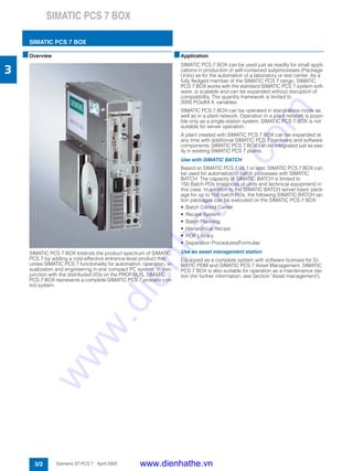
![Process I/O
ET 200M distributed I/O
Accessories
12/7Siemens ST PCS 7 · April 2005
12
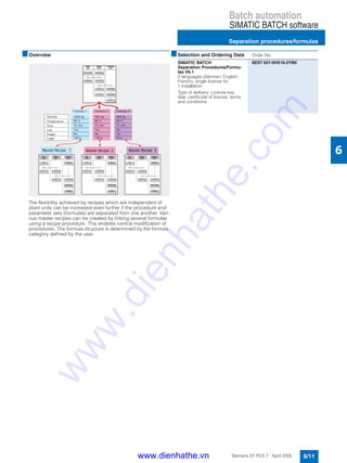
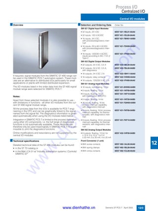
■Overview
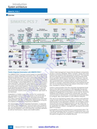
Following components are available as accessories for the
ET 200M:
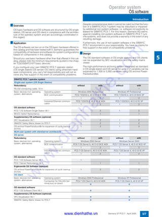
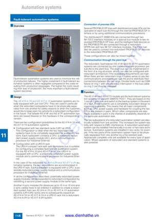
• Bus modules for hot swapping
• Profile rails for hot swapping
• Covers for bus backplanes and bus modules
• Front connectors
• Ex partition for ET 200M
• LK 393 cable duct
Ex partition
A mechanical isolation is required between the IM 153 interface
module and the first Ex I/O module. For the hot swapping func-
tion, an Ex partition is installed which guarantees the prescribed
isolation distance between non-intrinsically-safe and intrinsi-
cally-safe areas of the ET 200M distributed I/O system.
LK 393 cable duct
The LK 393 cable duct guarantees the prescribed isolation be-
tween the load voltage input and the intrinsically safe inputs/out-
puts. The cable duct is easy to fit following insertion of the load
voltage inputs L+.
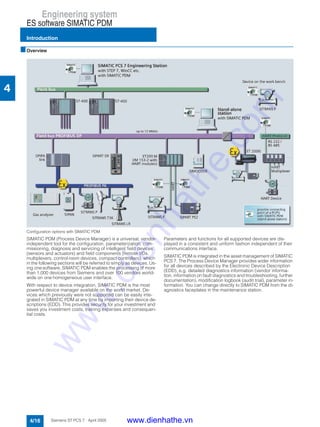
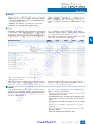
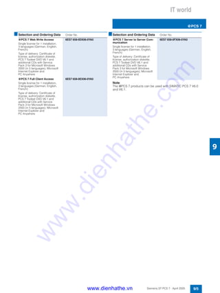
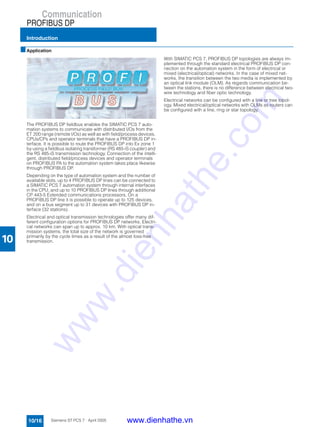
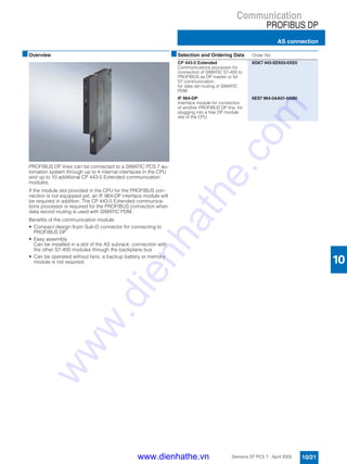
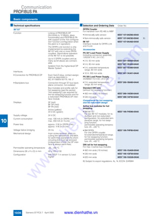
■Design
The picture shows the various bus modules being used for hot
swapping. Top: for redundant connection, Bottom: for singular
connection.
■Selection and Ordering Data Order No.
Bus Modules for Hot Swapping
• BM PS/IM for power supply and
IM 153,
incl. 1 bus module cover
6ES7 195-7HA00-0XA0
• BM 2x40 for 2 modules, each
40 mm wide
6ES7 195-7HB00-0XA0
• BM 1x80 for 1 module, 80 mm
wide
6ES7 195-7HC00-0XA0
• IM 153/IM 153
for two IM 153-2/-2 FOs for de-
sign of redundant systems
6ES7 195-7HD10-0XA0
Profile Rail for Hot Swapping
• 482 mm long (19 inches) 6ES7 195-1GA00-0XA0
• 530 mm long 6ES7 195-1GF30-0XA0
• 630 mm long 6ES7 195-1GG30-0XA0
Covers
Pack with 4 backplane bus cov-
ers and 1 bus module cover
6ES7 195-1JA00-0XA0
Front Connector (1 pcs)
• 20-pin, with screw contacts 6ES7 392-1AJ00-0AA0
• 20-pin, with spring contacts 6ES7 392-1BJ00-0AA0
• 40-pin, with screw contacts 6ES7 392-1AM00-0AA0
• 40-pin, with spring contacts 6ES7 392-1BM01-0AA0
Front connector for Ex analog
input module 6ES7 331-7SF00-
0AB0 (1 pcs)
• 20-pin, with screw contacts
enables an accuracy of ± 1.5 K
for the internal reference point
temperature when taking thermo-
element temperature measure-
ments in the measuring mode
"internal compensation" at ambi-
ent temperatures of 0 ... 60 °C
6ES7 392-1AJ20-0AA0
Ex partition for ET 200M
• Separation of IM 153 and down-
stream Ex modules within an
ET 200M line
• Mixed operation of non-Ex and
Ex modules within an ET 200M
line
• for supporting the hot swapping
function in connection with
IM 153-2
6ES7 195-1KA00-0XA0
LK 393 cable duct
[EEx ib] IIC-conform routing of
load voltage cable in front plug,
5 pcs
6ES7 393-4AA00-0AA0
www.dienhathe.vn
www.dienhathe.com](https://image.slidesharecdn.com/siemenssimaticsimaticpcs7-2-180725030538/85/Siemens-simatic-simatic-pcs-7-2-159-320.jpg)
![Process I/O
ET 200M distributed I/O
Bundles
12/8 Siemens ST PCS 7 · April 2005
12
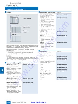
■Overview
Following preassembled bundles are available for ET 200M:
• I/O Subsystem ZuS:
ET 200M with hot swapping of modules, comprising
- profile rail for active bus modules,
- PS/IM bus module and
- IM 153-2 High Feature bus interface module
• IM 153 redundancy bundle:
comprising two IM 153-2 High Feature and one active
IM 153/IM 153 bus module, for operating the ET 200M on the
fault-tolerant AS 414H / AS 417H automation system.
• HART bundle with Ex analog input modules for redundant
PROFIBUS connection,
for operation in the AS 414H / AS 417H fault-tolerant automa-
tion system, comprising
- one 482 mm profile rail,
- one IM 153 / IM 153 active bus module,
- four 2x40 bus modules,
- two IM 153-2 High Feature and
- eight HART-capable Ex analog input modules.
B) Subject to export regulations: AL: N, ECCN: EAR99H
■Selection and Ordering Data Order No.
I/O Subsystem ZuS
ET 200M with hot swapping of
modules, comprising profile rail
for active bus modules size
482 mm (19 inches), PS/IM bus
module and
• IM 153-2 High Feature bus inter-
face module
for support of HART functional-
ity, F modules, FM modules,
Configuration in RUN" function;
also for use in redundant sys-
tems
6ES7 654-0XX06-1XA0 B)
IM 153 Redundancy Bundle
comprising two IM 153-2 High
Feature and one active
IM 153/IM 153 bus module,
for operating the ET 200M on the
fault-tolerant AS 414H / AS 417H
automation system
6ES7 153-2AR01-0XA0 B)
HART bundle with Ex AI mod-
ules [EEx ib]
for redundant PROFIBUS connec-
tion, comprising:
• two IM 153-2 High Feature inter-
face modules
• 8 Ex analog input modules with
HART
• one IM 153 / IM 153 bus module
• four 2x40 bus modules for
2 modules
• one 482 mm profile rail
6ES7 650-0XX06-0XX0 B)
www.dienhathe.vn
www.dienhathe.com](https://image.slidesharecdn.com/siemenssimaticsimaticpcs7-2-180725030538/85/Siemens-simatic-simatic-pcs-7-2-160-320.jpg)


![Process I/O
ET 200M distributed I/O
Ex modules [EEi xb]
12/16 Siemens ST PCS 7 · April 2005
12
■Overview
The following analog and digital I/O modules are suitable for use
in hazardous plants. They separate the non-intrinsically safe
electrical circuits of the automation system and the intrinsically
safe electrical circuits of the process. Sensors and actuators
suitable for placing in zone 1 and 2 hazardous areas as well as
intrinsically safe equipment compliant with DIN 50020 and
[EEx ib] IIC can be operated on these modules.
All Ex modules with HART come with diagnostics capability
(channel and module diagnostics).
■Selection and Ordering Data Order No.
Ex digital modules
Ex digital input module
• 4 NAMUR inputs in 4 channel
groups, redundant design pos-
sible
- Voltage supply to sensors
8.2 V
- Individually floating channels
- Wire break and short-circuit
monitoring (directly at the con-
tact for contacts with external
resistor circuit)
- Diagnostics inside module
- Required front connector:
20-pin
6ES7 321-7RD00-0AB0
Ex digital output module
• 4 outputs, 24 V DC / 10 mA in
4 channel groups, redundant
design possible
- Individually floating channels
- Wire break monitoring
- Short-circuit monitoring
- Diagnostics inside module
- Required front connector:
20-pin
6ES7 322-5SD00-0AB0
• 4 outputs, 15 V DC / 20 mA in
4 channel groups, redundant
design possible
- Individually floating channels
- Wire break monitoring
- Short-circuit monitoring
- Diagnostics inside module
- Required front connector:
20-pin
6ES7 322-5RD00-0AB0
Ex analog modules
Ex analog input module
• 4 inputs, 0/4...20 mA in
4 channel groups, redundant
design possible
- Individually floating channels
- Resolution 15 bit + sign
- Connection of 2-wire or 4-wire
transmitters possible
- Wire break monitoring
- Measurement range monitor-
ing
- Short-circuit proof
- Diagnostics inside module
- Required front connector:
20-pin
6ES7 331-7RD00-0AB0
• 8 inputs in 4 channel groups
- Resolution 15 bit + sign
- Thermocouples type T, U, E, J,
L, K, N, R, S, B (8 channels),
internal compensation; exter-
nal compensation with Pt100
(2 channels), compensating
box or 0/50°C cold junction
- Resistance thermometer
Pt100, Pt200, Ni100
(4 channels; 2-wire or 4-wire,
3-wire Pt100 on request)
- Wire break monitoring
- Diagnostics inside module
- Required front connector:
20-pin
Note:
A special front connector for the
Ex analog input module 6ES7
331-7SF00-0AB0 enables greater
accuracy when taking thermo-
couple temperature measure-
ments in "internal compensation"
measuring mode (see the section
"Accessories").
6ES7 331-7SF00-0AB0
Ex analog output module
• 4 outputs, 0/4...20 mA in
4 channel groups
- Individually floating channels
- Resolution 15 bit
- for 2-wire transmitters
- Wire break monitoring
- Diagnostics inside module
- Required front connector:
20-pin
6ES7 332-5RD00-0AB0
■Selection and Ordering Data Order No.
www.dienhathe.vn
www.dienhathe.com](https://image.slidesharecdn.com/siemenssimaticsimaticpcs7-2-180725030538/85/Siemens-simatic-simatic-pcs-7-2-168-320.jpg)
![Process I/O
ET 200M distributed I/O
Ex modules with HART
12/17Siemens ST PCS 7 · April 2005
12
■Overview
The Ex modules with HART (Highway Addressable Remote
Transducer), which can be used in distributed I/O devices of the
ET 200M (with IM 153-2 High Feature interface module), enable
HART devices with approval for potentially explosive areas to be
connected to SIMATIC PCS 7 automation systems .
All measurement transducers and HART actuators that are cer-
tified for digital communication with the HART protocol can be
connected through these modules.
In addition, conventional transducers with 4 to 20 mA technology
without HART protocol can also be connected
All Ex modules with HART come with diagnostics capability
(channel and module diagnostics).
■Application
HART is a serial transfer protocol which is used to transfer addi-
tional parameter data, such as measurement range, isolation
etc. to connected measuring transducers and actuators through
a 4 to 20 mA power loop. The Ex I/O modules offered here en-
able the HART protocol to also be used for communication with
HART devices in the hazardous area. The modules themselves
and the ET 200M are positioned in the safe area of in Ex zone 2.
A KEMA certificate confirms that the modules are approved for
operation with HART devices in the hazardous area.
■Function
The HART jobs can be initiated remotely for each channel
through PROFIBUS DP. This usually takes place from the central
engineering system of the SIMATIC PCS 7 process control sys-
tem using SIMATIC PDM.
The Ex modules with HART have the following characteristics:
• Connection compatibility with conventional analog modules of
the ET 200M
• Additional communication option through the current loop
• Low energy requirement
• 2 analog channels per module
• Each channel is a primary master of the HART protocol
• All channels can be operated by several clients simulta-
neously and independently of one another
• The channels are electrically isolated from one another
• Selectable current signal per channel:
- 0...20 mA (without HART function)
- 4...20 mA (with/without HART function)
Parameterization
• Remote parameterization is possible for:
- conversion time,
- resolution,
- limit values,
- alarms, etc.
• Remote parameterization of the HART measurement trans-
ducers and actuators is possible with SIMATIC PDM through
PROFIBUS DP
• It is still possible to parameterize the HART devices with an
operator terminal.
■Technical specifications
Detailed technical data of the Ex modules with HART can be
found
• in the IK PI catalog (section "Distributed I/Os“) or
• in the Mall / CA 01 at "Distributed I/Os / ET 200M“
B) Subject to export regulations: AL: N, ECCN: EAR99H
■Selection and Ordering Data Order No.
Ex Analog Input Module with
HART [EEx ib]
• 2 inputs, 0/4...20 mA in
2 channel groups
- Individually floating channels
- Resolution: 15 bit + sign
- Connection of 2 or 4-wire mea-
surement transducers possi-
ble
- Wire break monitoring
- Short-circuit-proof
- HART (2 or 4 wires)
- Front connector required:
20-pin
6ES7 331-7TB00-0AB0 B)
HART bundle with Ex OI mod-
ules [EEx ib]
for redundant PROFIBUS connec-
tion, comprising:
• two IM 153-2 High Feature inter-
face modules
• 8 Ex analog input modules with
HART
• one IM 153 / IM 153 bus module
• four 2x40 bus modules for
2 modules
• one 482 mm profile rail
Note: The load power supply
(PS 305/307) has to be ordered
separately
6ES7 650-0XX06-0XX0 B)
Ex Analog Output Module with
HART [EEx ib]
• 2 outputs, 0/4...20 mA in
2 channel groups
- Individually floating channels
- Resolution: 12 bit + sign
- For 2-wire actuators
- Wire break monitoring
- HART
- Front connector required:
20-pin
6ES7 332-5TB00-0AB0 B)
www.dienhathe.vn
www.dienhathe.com](https://image.slidesharecdn.com/siemenssimaticsimaticpcs7-2-180725030538/85/Siemens-simatic-simatic-pcs-7-2-169-320.jpg)
![Process I/O
ET 200M distributed I/O
F modules
12/18 Siemens ST PCS 7 · April 2005
12
■Overview
The special safety functions of the failsafe systems are coordi-
nated with the failsafe I/O modules of the distributed ET 200M
devices, whose job it is to also ensure plant safety should the
CPU fail. The failsafe signal modules of these peripheral devices
(digital inputs/outputs, analog input) are able to diagnose inter-
nal and external errors, have a redundant setup on account of
safety demands, and meet requirements up to SIL 3 (IEC 61508)
or AK 6 (VDE 0801).
The input modules work in SIL 3/AK 6 with internal 2-out-of-2
channel evaluation. A safety response is triggered immediately
there are any differences. The digital output modules enable
safe disconnection through a second disconnect path in the
event of a faulty output.
B) Subject to export regulations: AL: N, ECCN: EAR99H
■Selection and Ordering Data Order No.
SM 326F failsafe digital input
module
for floating contacts
• 24 inputs, 24 V DC,
floating in groups of 12, redun-
dant design possible
- 4 short-circuit-resistant sen-
sor power supplies, each for
6 channels, isolated in groups
of 3:
- External sensor power supply
possible
- SIL 2: single-channel evalua-
tion, 24 channels
- SIL 3: 2-out-of-2 evaluation on
the module, 12 channels (ad-
justable discrepancy time)
- Short-circuit monitoring to L+
- Discrepancy monitoring
- Diagnostics inside module
- ProfiSafe telegram
6ES7 326-1BK00-0AB0
• 8 inputs, NAMUR [EEx ib]
isolated by channel, redundant
design possible
- 8 short-circuit-resistant sen-
sor power supplies, each for
1 channel, mutually isolated
- SIL 2: single-channel evalua-
tion, 8 channels
- SIL 3: 2-out-of-2 evaluation on
the module, 4 channels (ad-
justable discrepancy time)
- Wire break and short-circuit
monitoring (for contacts with
external resistor circuit)
- Discrepancy monitoring
- Diagnostics inside module
- ProfiSafe telegram
6ES7 326-1RF00-0AB0
SM 326F failsafe digital output
module
• 10 outputs, 24 V DC, 2 A,
floating in groups of 5, redun-
dant design possible (outputs
with internal diode)
- SIL 2, SIL 3 parameterizable
(10 channels)
- Wire break and short-circuit
monitoring
- Diagnostics inside module
- ProfiSafe telegram
6ES7 326-2BF01-0AB0
SM 336F failsafe analog input
module
• 6 inputs, 4...20 mA, redundant
design possible
- Isolated from the backplane
bus
- 2-wire or 4-wire connection
- SIL 2: two-channel evaluation,
6 sensors
- SIL 3: two-channel evaluation,
12 sensors (adjustable toler-
ance window)
- Wire break monitoring
- Tolerance monitoring between
2 sensors (SIL 3)
- Diagnostics inside module
- ProfiSafe telegram
6ES7 336-1HE00-0AB0
Isolating module
For F modules, 40 mm wide
• For isolation of F and standard
modules in an ET 200M rack
• For signal isolation when using a
copper bus connection (only
F modules in a rack with
IM 153-2)
6ES7 195-7KF00-0XA0 B)
Isolating bus module
80 mm wide, for isolating module,
when using an active backplane
bus
6ES7 195-7HG00-0XA0
■Selection and Ordering Data Order No.
www.dienhathe.vn
www.dienhathe.com](https://image.slidesharecdn.com/siemenssimaticsimaticpcs7-2-180725030538/85/Siemens-simatic-simatic-pcs-7-2-170-320.jpg)


![Process I/O
ET 200iSP distributed I/O
Introduction
12/22 Siemens ST PCS 7 · April 2005
12
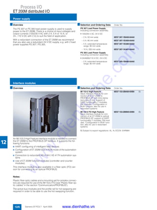
■Overview
The ET 200iSP is a modular, intrinsically-safe I/O station in IP30
degree of protection, and can be configured with up to
32 electronics modules (4/8-channel). The range of electronics
modules covers:
• 8-channel digital input module DI, can also be used as
counter or frequency meter
• 4-channel digital output module DO
• 4-channel analog input modules AI for temperature measure-
ments with resistance thermometer or thermocouple
• 4-channel analog input modules AI for connection of 2/4-wire
transmitters with or without HART functionality
• 4-channel analog output module AO for connection of field de-
vices with or without HART functionality
The ET 200iSP appropriate for gaseous and dusty atmospheres
can be installed, according to CENELEC II 2 G (1) GD EEx d e
[ib/ia] IIC T4 directly in the Ex zones 1, 2, 21 or 22 as well as in
non-hazardous areas. The intrinsically-safe sensors, actuators
and HART field devices can also be located in zone 0 or 20 if
necessary.
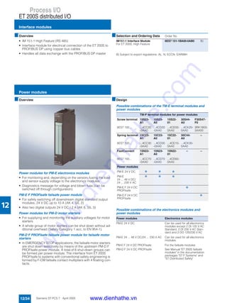
■Design
The ET 200iSP consists of:
• a carrier system with terminal modules for prewiring, and also
for inserting power supply, interface and electronics modules,
mounted on an S7-300 rail,
• 1 or 2 (redundant) power supply modules PS with pressurized
enclosure,
• 1 or 2 (redundant) IM 152 interface modules for PROFIBUS
DP,
• up to 32 electronics modules (4/8-channel) in any combina-
tion, and
• a terminating module (included in scope of delivery of terminal
modules for the PROFIBUS interface).
Assembly is quick and easy:
• Latching of terminal modules onto the S7-300 rail
• Prewiring of process signal cables on the terminal modules
using spring-loaded or screw-type connections
• Plugging-in of power supply, interface and electronics mod-
ules without the need for additional tools.
The maximum number of electronics modules which can be
used per station may be limited depending on the current con-
sumption of the modules required to solve the automation task.
However, up to 16 electronics modules can be used without lim-
itation.
If the ET 200iSP is used in a hazardous area, it must be installed
in an Ex e housing which at least corresponds to the IP54 degree
of protection. Appropriate versions of an IP65 housing are of-
fered in the section on stainless steel wall housings.
Exceptional features of the ET 200iSP architecture
• Installation and testing of the wiring is possible in advance
without the electronics module.
• Isolation of the mechanical and electronic systems, in con-
junction with the independent process wiring, permits fast and
easy replacement of the electronics modules.
• Mechanical coding which is carried out when an electronics
module is plugged onto a terminal module for the first time
prevents the connection of incorrect replacement modules.
• Hot swapping of the power supply modules and electronics
modules is possible without a fire certificate.
www.dienhathe.vn
www.dienhathe.com](https://image.slidesharecdn.com/siemenssimaticsimaticpcs7-2-180725030538/85/Siemens-simatic-simatic-pcs-7-2-174-320.jpg)
![Process I/O
ET 200iSP distributed I/O
Introduction
12/23Siemens ST PCS 7 · April 2005
12
■Integration
Distributed ET 200iSP stations are connected to the SIMATIC
PCS 7 automation systems (controllers) via the PROFIBUS DP,
which can be routed intrinsically-safe into Ex zone 1 using an
isolating transformer (RS485-iS coupler) as barrier. Data transfer
rates of up to 1.5 Mbit/s are possible.
The modern architecture with independent wiring and automatic
slot coding supports simple and reliable hot swapping of individ-
ual modules without a fire certificate. To increase plant availabil-
ity, both the power supply and the PROFIBUS DP interface can
be of redundant design.
The ET 200iSP is integrated into SIMATIC PCS 7 using standard
driver blocks. You can therefore configure and parameterize the
ET 200iSP in the SIMATIC Manager of the engineering system
extremely simply using HW Config. The system function CiR
(Configuration in Run) is also supported, and permits the follow-
ing changes to be made to the configuration during runtime:
• Adding of an ET 200iSP station
• Adding of a module in an ET 200iSP station
• Reparameterization of modules.
Vendor-specific information and maintenance data are saved
powerfail-proof on the electronics modules.
The existing standard diagnostics drivers preprocess the
diagnostics messages generated by internal or external faults
(e.g. wire breakage or short-circuit) as well as status messages
of the connected HART field devices for the host operator sys-
tem and the maintenance station of the PCS 7 asset manage-
ment. The ET 200iSP and the HART field devices can also be
parameterized using SIMATIC PDM (process device manager).
With SIMATIC PDM you can directly access the HART field de-
vices on the ET 200iSP by routing via PROFIBUS DP.
■Technical specifications
For detailed technical specifications, especially on individual
components such as power supply module, interface module or
electronics modules, see:
• Catalog IK PI or
• the Mall / Catalog CA 01 under "Distributed I/Os / ET 200iSP"
ET 200iSP – general
Degree of protection IP30
Ambient temperature -20 ... +70 °C
Vibration resistance 0.5 g continuously, 1 g occasion-
ally
Standards and approvals
• PROFIBUS EN 50170, Volume 2
• EU directive 94/9/EC (ATEX 100a)
• CENELEC II 2 G (1) GD Eex d e [ib/ia] IIC T4
• IEC IEC61131, Part 2
• CE According to 89/336/EEC and
73/23/EEC
www.dienhathe.vn
www.dienhathe.com](https://image.slidesharecdn.com/siemenssimaticsimaticpcs7-2-180725030538/85/Siemens-simatic-simatic-pcs-7-2-175-320.jpg)


![Process I/O
ET 200iSP distributed I/O
Electronics modules
12/27Siemens ST PCS 7 · April 2005
12
B) Subject to export regulations: AL: N, ECCN: EAR99H
For further accessories such as labeling strips or plates, see Catalog
IK PI or the A&D Mall/CA 01 under "ET 200iSP distributed I/O".
■Selection and Ordering Data Order No.
Digital electronics modules
Digital input modules
8 DI NAMUR
• 8 x NAMUR (NAMUR sensor
on/off, NAMUR changeover con-
tact) or connected/non-connect-
ed inputs (single/changeover
contact)
• 2 channels optionally usable as
counters (max. 5 kHz) or fre-
quency meters (1 Hz ... 5 kHz)
• Time tagging 5 ms, rising or fall-
ing edge
• Wire break monitoring
• Short-circuit monitoring
• Sensor power supply monitoring
• Flutter monitoring
6ES7 131-7RF00-0AB0 B)
Digital output modules
4 DO; 23.1 V DC/20 mA
• Short-circuit monitoring
• Wire break monitoring
• Parameterizable connection of
substitute value in case of CPU
failure
• Load-free switching of outputs
via external intrinsically-safe sig-
nal
6ES7 132-7RD00-0AB0 B)
4 DO; 17.4 V DC/27 mA
• Short-circuit monitoring
• Wire break monitoring
• Parameterizable connection of
substitute value in case of CPU
failure
• Channels can be connected in
parallel
• Load-free switching of outputs
via external intrinsically-safe sig-
nal
6ES7 132-7RD10-0AB0 B)
4 DO; 17.4 V DC/40 mA
• Short-circuit monitoring
• Wire break monitoring
• Parameterizable connection of
substitute value in case of CPU
failure
• Channels can be connected in
parallel
• Load-free switching of outputs
via external intrinsically-safe sig-
nal
6ES7 132-7RD20-0AB0
Analog electronics modules
Analog input modules
4 AI I 2 WIRE HART
• 4 x 4...20 mA, HART, 2-wire
transmitter
• Transmitter load: max. 750 Ω
• Resolution 12 bit + sign
• Short-circuit monitoring
• Wire break monitoring
6ES7 134-7TD00-0AB0 B)
4 AI I 4 WIRE HART
• 4 x 0/4...20 mA, HART, 4-wire
transmitter
• Transmitter load: max. 750 Ω
• Resolution 12 bit + sign
• Wire break monitoring
6ES7 134-7TD50-0AB0
4 AI RTD
• 4 x RTD, resistance thermometer
Pt100/Ni100
• 2-, 3-, 4-wire
• Resolution 15 bit + sign
• Short-circuit monitoring
• Wire break monitoring
6ES7 134-7SD50-0AB0
4 AI TC
• 4 x TC (thermocouples)
• Type B [PtRh-PtRh]
• Type N [NiCrSi-NiSi]
• Type E [NiCr-CuNi]
• Type R [PtRh-Pt]
• Type S [PtPh-Pt]
• Type J [Fe-CuNi]
• Type L [Fe-CuNi]
• Type T [Cu-CuNi]
• Type K [NiCr-Ni]
• Type U [Cu-CuNi]
• Resolution 15 bit + sign
• Internal temperature compensa-
tion possible using TC sensor
module (included in scope of
delivery of module)
• External temperature compen-
sation via PT100 connected to
RTD module of same ET 200iSP
station
• Wire break monitoring
6ES7 134-7SD00-0AB0
Analog output modules
4 AO I HART
• 4 x 0/4...20 mA, HART (max.
load 750 Ω)
• Resolution 14 bit
• Short-circuit monitoring
• Wire break monitoring
• Parameterizable substitute val-
ue in case of CPU failure
6ES7 135-7TD00-0AB0 B)
Terminal modules
TM-EM/EM60S terminal module
for ET 200iSP
for two electronics modules,
screw terminals
6ES7 193-7CA00-0AA0 B)
TM-EM/EM60C terminal module
for ET 200iSP
for two electronics modules,
spring-loaded terminals
6ES7 193-7CA10-0AA0 B)
Accessories
Reserve module
for any electronics module
6ES7 138-7AA00-0AA0 B)
S7-300 rail
• 585 mm long, suitable for as-
sembly of ET 200iSP in a 650-
mm wide wall housing
6ES7 390-1AF85-0AA0
• 885 mm long, suitable for as-
sembly of ET 200iSP in a 950-
mm wide wall housing
6ES7 390-1AJ85-0AA0
■Selection and Ordering Data Order No.
www.dienhathe.vn
www.dienhathe.com](https://image.slidesharecdn.com/siemenssimaticsimaticpcs7-2-180725030538/85/Siemens-simatic-simatic-pcs-7-2-179-320.jpg)


![Appendix
Training
14/2 Siemens ST PCS 7 · April 2004
14
■Training is decisive for your success
SITRAIN®
- the Siemens Training for Automation and Industrial
Solutions - provides you with comprehensive support when solv-
ing your tasks.
Training by the market leader in automation, plant installation
and support permits you to make your decisions with certainty
and full command. Especially where the optimum and efficient
use of products and plants are concerned. You can eliminate de-
ficiencies in existing plants, and exclude expensive faulty plan-
ning right from the beginning.
All in all, this represent an enormous gain for your company:
shortened startup times, optimized plant components,
faster troubleshooting, reduced down times. In other words,
increased profits and lower costs.
Top trainers
Our trainers know their topics in practice, and possess compre-
hensive didactic experience. Course developers have a direct
wire to product development, and directly pass on their knowl-
edge to the trainers.
Practical experience
The practical experience of our trainers makes it possible for
them to pass on theoretical matter in a plausible manner. But
since it is known that all theory is drab, we attach great impor-
tance to practical exercises which can comprise up to half of the
course time. You can therefore immediately implement your new
knowledge in practice. We train you on state-of-the-art methodi-
cally/didactically designed training equipment. You feel abso-
lutely certain when trained in this manner.
Wide variety
With a total of approx. 300 local attendance courses, we train the
complete range of A&D products and a large portion of the sys-
tem solutions from I&S. Telecourses, teach-yourself software and
seminars presented on the Web supplement our classical range
of courses.
Close to our customers
The distance is short. You can find us approx. 60 times in Ger-
many, and worldwide in 62 countries. You wish to have individual
training instead of one of our 300 courses? No problem: we will
provide a program tailored exactly to your personal require-
ments. Training can be carried out in our Training Centers or at
your company.
■The right mixture: blended learning
Blended learning is understood to be the combination of various
training media and sequences. For example, a local attendance
course in a Training Center can be optimally supplemented by a
teach-yourself program as preparation or follow-up. Further-
more, SITRAIN utilizes supported online training for live instruc-
tion on the Internet at agreed times.
The right mixture is the solution. Therefore blended learning
can convey complex topics well, and train networked think-
ing. Additional effect: reduced travelling costs and periods
of absence through training sequences independent of loca-
tion and time.
■The international training portal
www.siemens.com/sitrain
All training facilities at a glance: search in the worldwide range
of courses at leisure, call up all course dates online, utilize the
daily updated display of vacant course spaces - and register di-
rectly.
■Customer comments on Sitrain
" ... the good course documents, competence and flexibility con-
vinced me."
[Manfred Riek from Festo Systemtechnik, responsible for plan-
ning the basic and further training of project engineers]
" ... represents effective training, constructive dialogs, and solu-
tions which provide great help."
[Günter Niedermaier, electrical design manager at AMT, Aalen]
■Contact
Visit us on the Internet at:
www.siemens.com/sitrain
or let us advise you personally. You can request our latest train-
ing catalog from:
Course office, Infoline Germany:
Tel.: 01805 / 23 56 11 (0.12 €/Min)
Fax: 01805 / 23 56 12
www.dienhathe.vn
www.dienhathe.com](https://image.slidesharecdn.com/siemenssimaticsimaticpcs7-2-180725030538/85/Siemens-simatic-simatic-pcs-7-2-202-320.jpg)


The document is a catalog for the SIMATIC PCS 7 process control system, detailing its components, features, and integration with totally integrated automation solutions for various industries. It emphasizes the benefits of modular architecture, open communication standards, and cost-effectiveness throughout the product lifecycle. Additionally, it includes information on documentation formats available for users and compatibility with other Siemens automation systems.


![E20001 a239-p280-x-7600[1]](https://cdn.slidesharecdn.com/ss_thumbnails/e20001-a239-p280-x-76001-140908052339-phpapp01-thumbnail.jpg?width=640&height=640&fit=bounds)


