Download to read offline


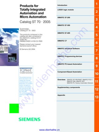
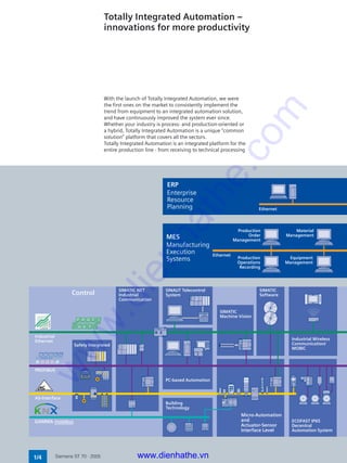
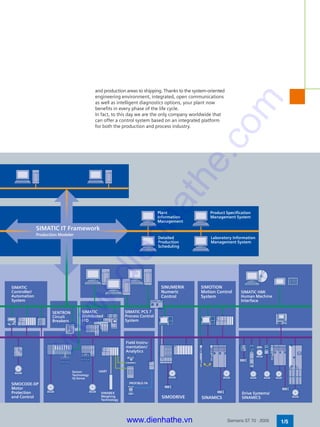
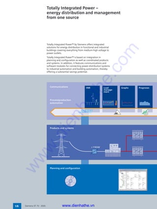
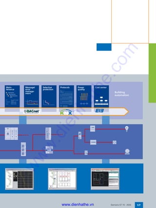
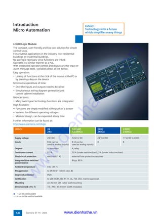
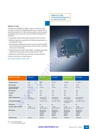
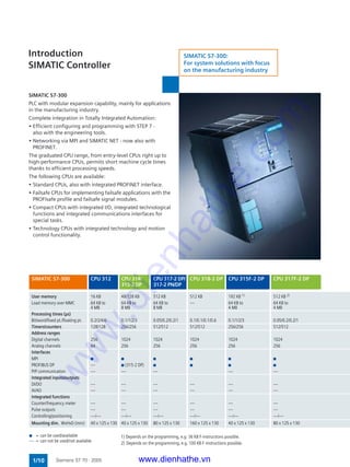
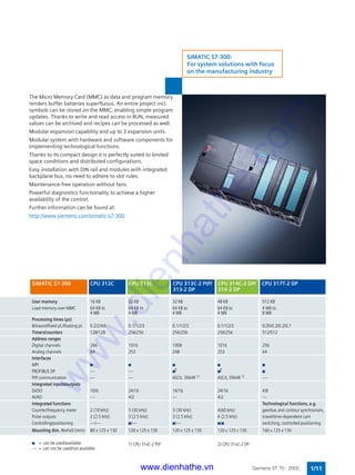
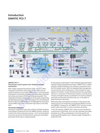
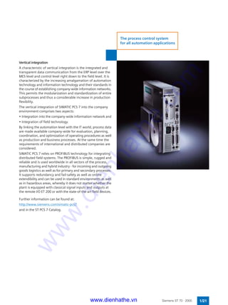
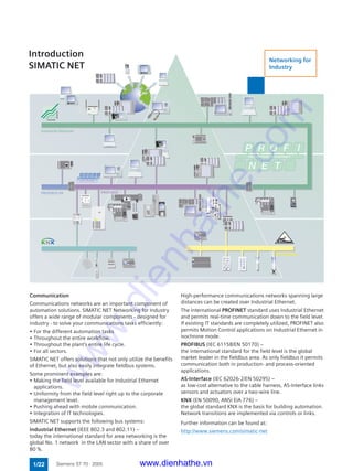
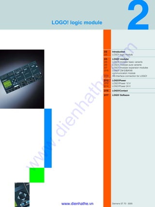
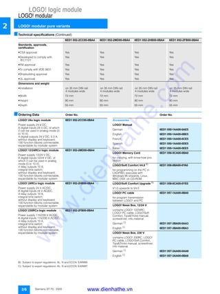
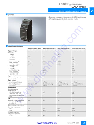
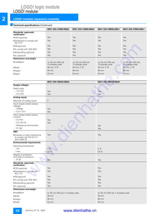
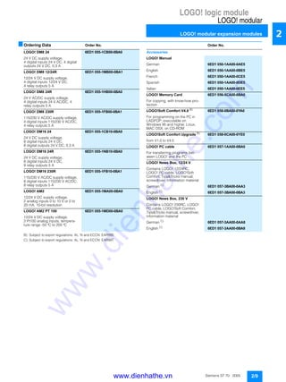
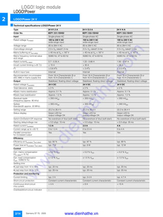
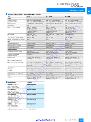
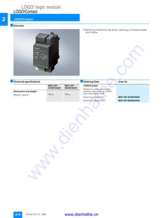
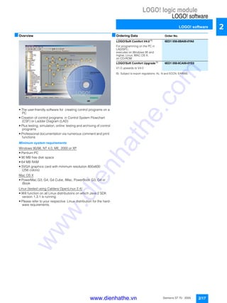
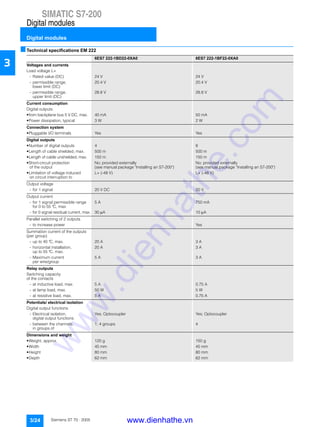
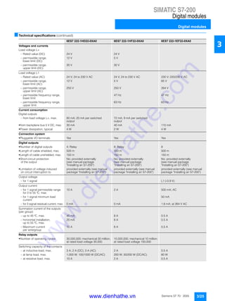
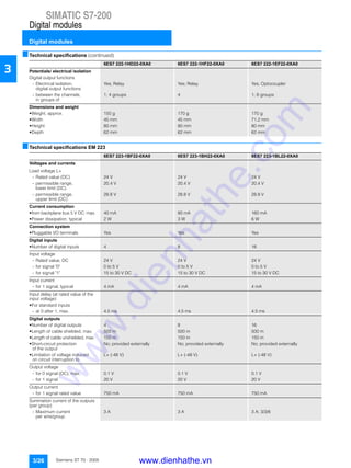
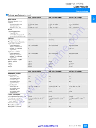

The document is a catalog from Siemens detailing their products for automation and drives, specifically focusing on totally integrated automation and micro-automation solutions. It emphasizes the importance of quality management certifications and provides examples of various automation systems such as SIMATIC S7-200 and S7-300 along with their features and specifications. The catalog also includes information about energy distribution and management solutions and highlights Siemens' commitment to innovative and integrated automation technology.


