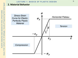
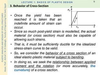
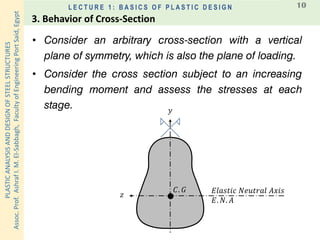
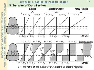
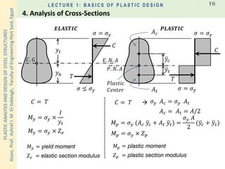
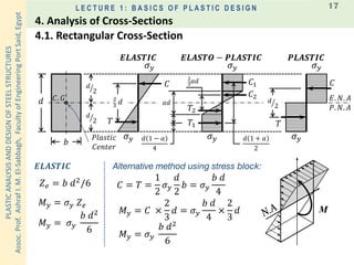
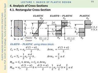
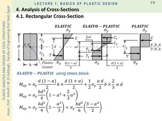
This document discusses the basics of plastic design of steel structures. It introduces plastic analysis as a way to calculate the actual failure load of a structure, which can be greater than the elastic load capacity. Idealized stress-strain curves are used to model the behavior of elastic-plastic materials. The behavior of cross-sections under bending is examined, including the formation of plastic hinges that allow rotation beyond the yield point. Assumptions and methods for plastic analysis of cross-section properties like yield moment and plastic moment are also presented.
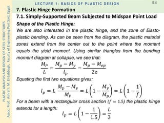
![PLASTICANALYSISANDDESIGNOFSTEELSTRUCTURES
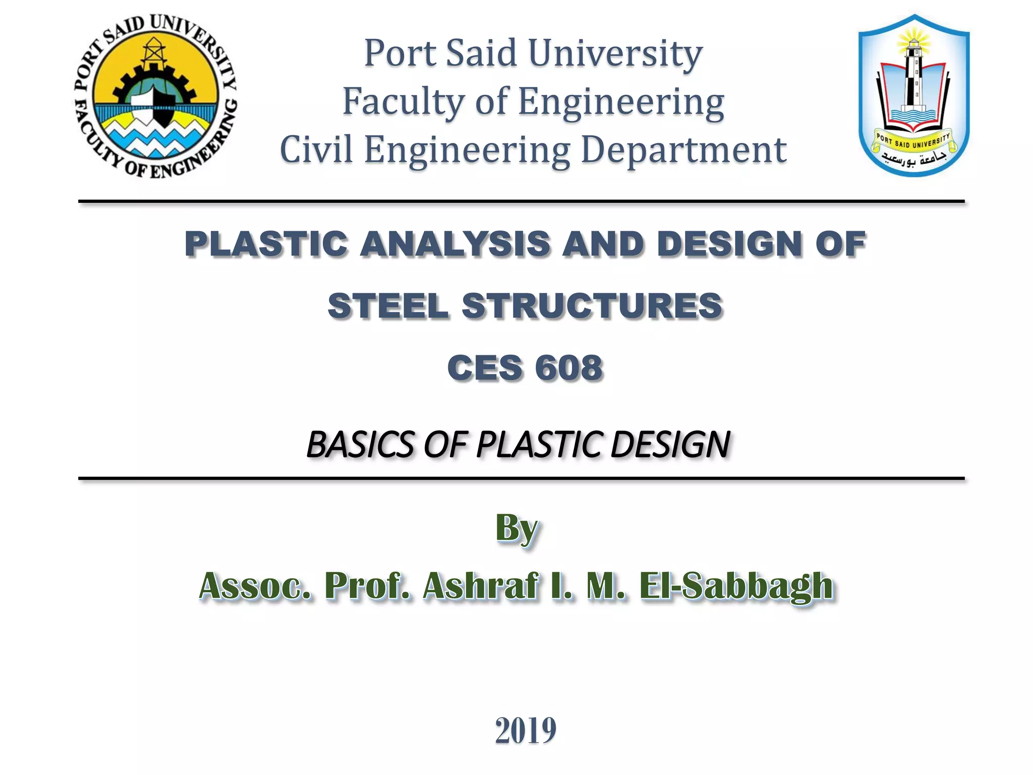
Assoc.Prof.AshrafI.M.El-Sabbagh,FacultyofEngineeringPortSaid,Egypt
L E C T U R E 1 : B A S I C S O F P L A S T I C D E S I G N 38
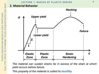
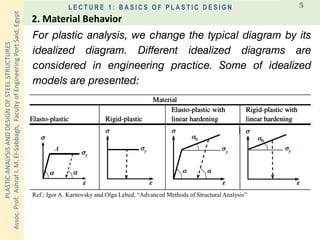
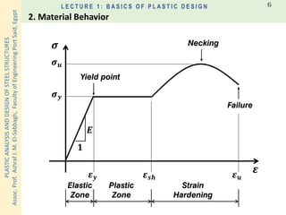
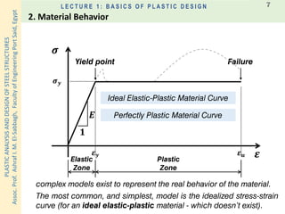
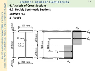
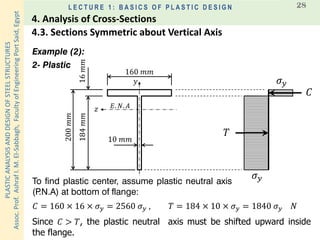
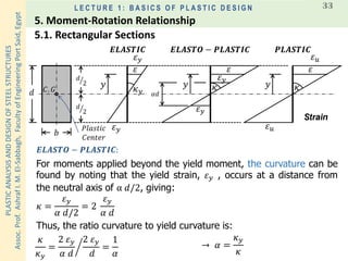
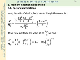
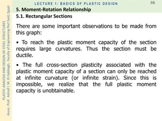
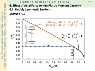
Lastly, for other cross-section shapes we have the
moment-curvature relations shown in the following figure.
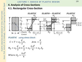
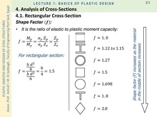
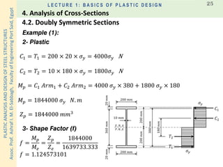
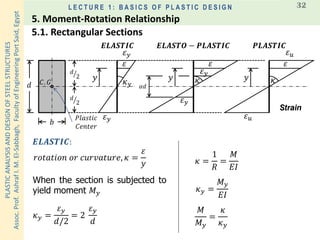
5.1. Rectangular Sections
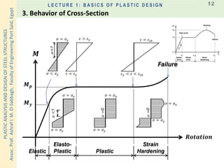
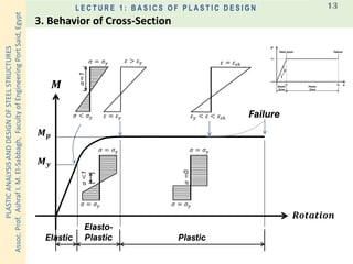
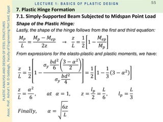
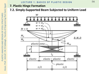
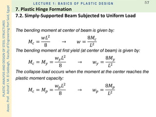
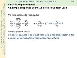
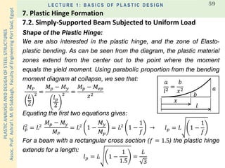
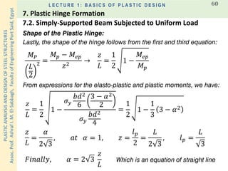
5. Moment-Rotation Relationship
𝒇𝒓𝒐𝒎 [𝑪𝒐𝒍𝒊𝒏 𝑪𝒂𝒑𝒓𝒂𝒏𝒊]](https://image.slidesharecdn.com/001-basics-of-plastic-analysis-191107085920/85/Part-1-basics-of-plastic-analysis-38-320.jpg)
![PLASTICANALYSISANDDESIGNOFSTEELSTRUCTURES
Assoc.Prof.AshrafI.M.El-Sabbagh,FacultyofEngineeringPortSaid,Egypt
L E C T U R E 1 : B A S I C S O F P L A S T I C D E S I G N 50
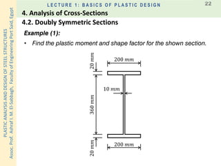
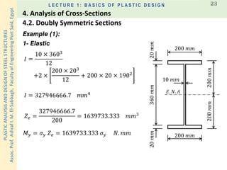
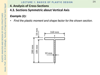
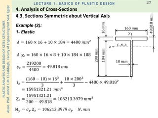
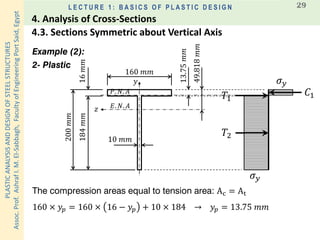
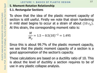
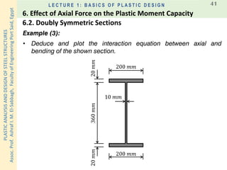
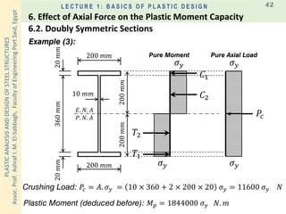
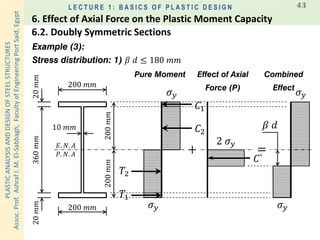
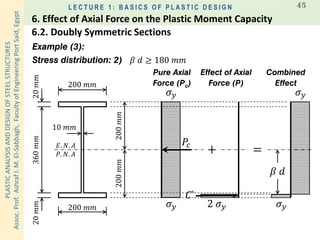
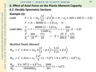
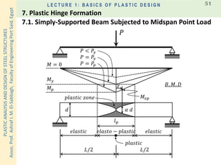
Example (3):
𝟗𝟐𝟐𝟎
𝟏𝟎𝟕𝟓𝟗
𝑴 𝒑𝒄
𝑴 𝒑
+
𝟑𝟒𝟐
𝟑𝟕𝟏
𝑷
𝑷 𝒄
+
𝟐𝟗
𝟑𝟕𝟏
𝑷
𝑷 𝒄
𝟐
= 𝟏
𝑴 𝒑𝒄
𝑴 𝒑
+
𝟖𝟒𝟏
𝟒𝟔𝟏
𝑷
𝑷 𝒄
𝟐
= 𝟏
𝑷
𝑷 𝒄
> 𝟎. 𝟏𝟓:
𝑴 𝒑𝒄
𝑴 𝒑
= 𝟏. 𝟏𝟖 𝟏 −
𝑷
𝑷 𝒄
𝑷
𝑷 𝒄
≤ 𝟎. 𝟏𝟓:
𝑴 𝒑𝒄
𝑴 𝒑
= 𝟏. 𝟎
𝑨𝒑𝒑𝒓𝒐𝒙𝒊𝒎𝒂𝒕𝒆:
6.2. Doubly Symmetric Sections
6. Effect of Axial Force on the Plastic Moment Capacity
𝒇𝒓𝒐𝒎 [𝑪𝒐𝒍𝒊𝒏 𝑪𝒂𝒑𝒓𝒂𝒏𝒊]
200 𝑚𝑚
200 𝑚𝑚
360𝑚𝑚20𝑚𝑚20𝑚𝑚
10 𝑚𝑚](https://image.slidesharecdn.com/001-basics-of-plastic-analysis-191107085920/85/Part-1-basics-of-plastic-analysis-50-320.jpg)


![Geotechnical Engineering-II [Lec #5: Triaxial Compression Test]](https://cdn.slidesharecdn.com/ss_thumbnails/5-180930132716-thumbnail.jpg?width=640&height=640&fit=bounds)

![[M. bill wong]_plastic_analysis_and_design_of_stee](https://cdn.slidesharecdn.com/ss_thumbnails/m-200924031016-thumbnail.jpg?width=640&height=640&fit=bounds)


