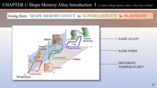
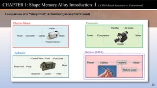
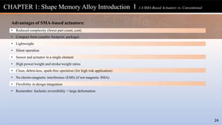
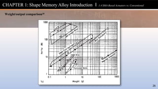
The document provides an in-depth overview of shape memory alloys (SMAs), detailing their historical background, material science, and applications, particularly in aeronautics and space. It explains how SMAs operate through various mechanisms and their advantages over conventional materials, such as reduced complexity and lightweight characteristics. Additionally, it covers practical considerations for mechanism design using SMAs and includes case studies to enhance understanding.


![Property Name Nom. Units
Austenite start temperature AS °C
Austenite finish temperature AF °C
Martensite start temperature MS °C
Martensite finish temperature MF °C
Hysteresis (AF - MS) ΔTH °C
Full width (AF - MF) ΔTFW °C
Yield strength σYS MPa
Maximum-strain/elongation εMax/εElong %
Maximum-stress/UTS σMax/σUTS MPa
Unloading strain εUnload %
Austenite start strain εAS %
Austenite finish strain εAF %
Martensite start strain εMS %
Martensite finish strain εMF %
Austenite slope n/a %/°C
Transformation slope n/a %/°C
Martensite slope n/a %/°C
Cooling trans. strain (εMF - εMS) εCool %
Heating trans. strain (εAS - εAF) εHeat %
Lower cycle temperature strain εLCT %
Upper cycle temperature strain εUCT %
Residual martensite strain εMRes %
Residual austenite strain εARes %
Work [(εAS - εAF) * σApp * 100] n/a J/cm3
Actuation strain (εLCT - εUCT) εAct %
Isobaric response
Isothermal response
+
recovery
CHAPTER 2: Shape Memory Alloys To Mechanisms l 2.2 Thermal and Mechanical Variables
36](https://image.slidesharecdn.com/shape-memory-alloysbookfinal-240508174446-5ecede71/85/Shape-Memory-Alloys_Book_Final-presentation-pptx-36-320.jpg)


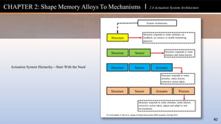

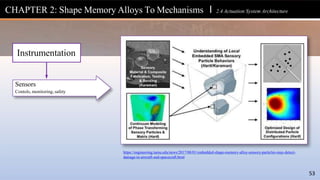
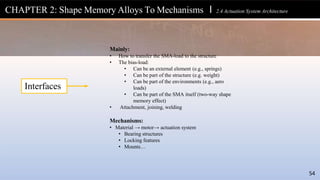
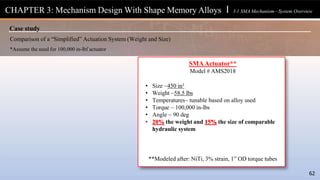
![CHAPTER 2: Shape Memory Alloys To Mechanisms l 2.4 Actuation System Architecture
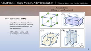
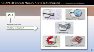
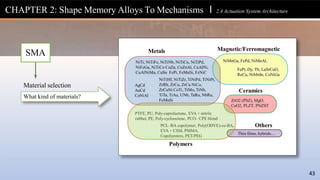
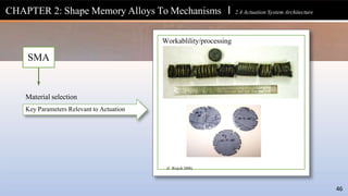
Material selection
What kind of materials?
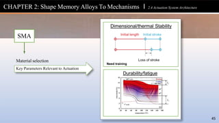
Temperature and strain capability[23]
SMA
44](https://image.slidesharecdn.com/shape-memory-alloysbookfinal-240508174446-5ecede71/85/Shape-Memory-Alloys_Book_Final-presentation-pptx-44-320.jpg)

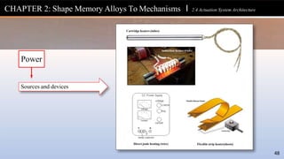
![CHAPTER 2: Shape Memory Alloys To Mechanisms l 2.4 Actuation System Architecture
Heating/cooling methods[24]
Power
49](https://image.slidesharecdn.com/shape-memory-alloysbookfinal-240508174446-5ecede71/85/Shape-Memory-Alloys_Book_Final-presentation-pptx-49-320.jpg)


![• What efficiency and response time is needed?
o Energy and mechanical efficiencies of SMA components
o Weight savings (mass efficiency) may be of higher priority
o Cyclic frequency
• What is the proposed environment?
o Environment and thermal conditions
o Commercial availability of alloys, transformation temperatures
are limited to ~115 C
o Vibration, humidity, corrosive elements, and bio-compatibility
• What relevant standards and documents are available?
o Required for certification
o Examples include ASTM standards: application specific
documents, certification documentation, and supplier data
• What other components/system will be required?
o System components
• Why use shape memory alloys?
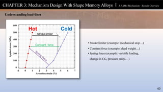
63
o Identify potential advantages over other systems
• What are the application requirements?
o Required properties and performance
characteristics of SMA element
o Lifecycle, response time, conditions
o Choice of material, form, size, and control
methods
• What are the cost/expenditure limits?
o Raw SMA material, processing, and fabrication
o Cost per device is critical to the business case
• What is the availability and size of the SMA element?
o Input (power) and required output (work) of the
SMA element
o Forms (e.g., strips, rods, sheets, wires, springs,
tubes, etc…) in various sizes
o Availability and required volume of the material
from a commercial supplier or other source
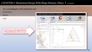
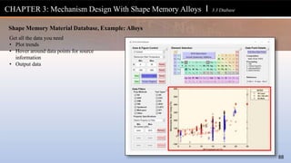
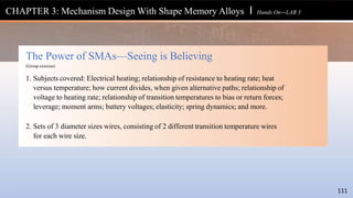
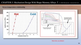
CHAPTER 3: Mechanism Design With Shape Memory Alloys l 3.2 Design Tools
Does SMA make sense for my application?[27]](https://image.slidesharecdn.com/shape-memory-alloysbookfinal-240508174446-5ecede71/85/Shape-Memory-Alloys_Book_Final-presentation-pptx-63-320.jpg)
![Courtesy: CASMART
Design Modeling Characterization
Load bias
Methodology
64
Durability
methodology
Standards
Model
Implementation
Model
selection
Model
calibration
Case
studies
Design
optimization
System
integration
Controls
Evaluati on
Alloy
selection
Actuator
processing
Design, Build, Test, Learn
CHAPTER 3: Mechanism Design With Shape Memory Alloys l 3.2 Design Tools
Design cycle [27]](https://image.slidesharecdn.com/shape-memory-alloysbookfinal-240508174446-5ecede71/85/Shape-Memory-Alloys_Book_Final-presentation-pptx-64-320.jpg)
![Design
Case
studies
Courtesy: CASMART
65
Design
optimization
System
integration
Controls
Actuator
processing
Why use shape memory alloys?
Application need
Availability/cost
Evaluation
Influencing factors
Design properties
Testing
Alloy
selection
Thermo-mechanical training
Heat treatment
Fabrication
Active/passive control
Healing cycles
Components of SMA system
Integrated mechanisms
Optimization methodologies
Iterations
Design, Build, Test, Learn
CHAPTER 3: Mechanism Design With Shape Memory Alloys l 3.2 Design Tools
Design cycle [27]
Concepts
Prototypes](https://image.slidesharecdn.com/shape-memory-alloysbookfinal-240508174446-5ecede71/85/Shape-Memory-Alloys_Book_Final-presentation-pptx-65-320.jpg)
![Modeling
Model
Implementation
Model
selection
Model
calibration
Validation and prediction
Terminology
Micromechanics models
Continuum models
Engineering models
Calibration techniques
Model calibration data
Validation data
• First-order calculations
Calculations using vendor-supplied or previously
determined properties
• Engineering models
Developed from empirical data
Wire, springs, tubes
• Constitutive models
Numerical codes (e.g., FEA)
CHAPTER 3: Mechanism Design With Shape Memory Alloys l 3.2 Design Tools
Design cycle [27]
Courtesy: CASMART
66](https://image.slidesharecdn.com/shape-memory-alloysbookfinal-240508174446-5ecede71/85/Shape-Memory-Alloys_Book_Final-presentation-pptx-66-320.jpg)
![Characterization
Load bias
Methodology
Durability
methodology
Standards
Load bias data interpretation
Loading/heating rates
Multi-axial testing
Measurement tolerances
Material/system fatigue
Training/cycling
Test parameter measurement
Thermal-mechanical testing
Terminologies
• Material level
• Sub-system level
• Final integrated system level
CHAPTER 3: Mechanism Design With Shape Memory Alloys l 3.2 Design Tools
Design cycle [27]
Courtesy: CASMART
67](https://image.slidesharecdn.com/shape-memory-alloysbookfinal-240508174446-5ecede71/85/Shape-Memory-Alloys_Book_Final-presentation-pptx-67-320.jpg)
![CHAPTER 3: Mechanism Design With Shape Memory Alloys l 3.2 Design Tools
68
Wire Design Tool[28]
• User-input martensite and austenite
stress-strain responses
Solve for strokes, loads, and predicted life](https://image.slidesharecdn.com/shape-memory-alloysbookfinal-240508174446-5ecede71/85/Shape-Memory-Alloys_Book_Final-presentation-pptx-68-320.jpg)
![0
50
100
300
250
200
150
350
500
450
400
0.00 0.01 0.04 0.05
Stress
[MPa]
0.02 0.03
Strain [mm/mm]
1st Cycle Austenite (150C)
1st Cycle Martensite (RT)
69
Stress [MPa]
As-Received
Martensite
Strain
As-Received
Austenite Strain
10th Cycle
Martensite
Strain
10th Cycle
Austenite Strain
0 0.000 0 0.02 0
50 0.003 0.001 0.029 0.001
100 0.020 0.002 0.033 0.002
150 0.028 0.003 0.034 0.003
200 0.032 0.004 0.035 0.004
250 0.035 0.005 0.036 0.005
300 0.037 0.006 0.037 0.006
400 0.040 0.008 0.04 0.008
500 0.042 0.011 0.041 0.01
Material Input Data: NiTi Wire Example
CHAPTER 3: Mechanism Design With Shape Memory Alloys l 3.2 Design Tools
Wire Design Tool[28]
• Wire is rigidly anchored at one end and attached to a linear bias spring at the other](https://image.slidesharecdn.com/shape-memory-alloysbookfinal-240508174446-5ecede71/85/Shape-Memory-Alloys_Book_Final-presentation-pptx-69-320.jpg)
![Name Unit Type Description and range for input Reset
value
Symbo
l
OneWayLength mm Input: wire >0, length of one or more wires
mechanically in series
100 L
Diameter mm Input: wire >0, wire diameter 0.25 d
# of ParallelWires unit Input: wire >0, # of mechanically parallel wires 1 n
DispM_Bias_Met mm Input: system >0, displacement where martensite
curve and linear bias spring intercepts
5% of L Dint
SpringConstant N/m
m
Input: system Must be a number 1 k
ColdStop mm Input: system Wire stop position at cold Dint Dcold
TargetStroke mm Input: system >0, total motion amount left of
minimum of Dint or Dcold
2% of L D
Volume mm³ Output -----------------------------------------------
-
---------- V
MaxWireStress MPa Output Maximum stress the wire experiences ---------- Smax
• Example output or solution message of the wire design tool
CHAPTER 3: Mechanism Design With Shape Memory Alloys l 3.2 Design Tools
70
Wire Design Tool[28]
• Required Input Parameters for Wire Design Tool](https://image.slidesharecdn.com/shape-memory-alloysbookfinal-240508174446-5ecede71/85/Shape-Memory-Alloys_Book_Final-presentation-pptx-70-320.jpg)

![CHAPTER 3: Mechanism Design With Shape Memory Alloys l 3.2 Design Tools
72
Wire Design Tool[28]
• Input parameters that describe the
material and actuator application
• Output deflection and stress in
austenite and martensite as a
function of applied load
Solve for strokes, loads, as
a function of geometries](https://image.slidesharecdn.com/shape-memory-alloysbookfinal-240508174446-5ecede71/85/Shape-Memory-Alloys_Book_Final-presentation-pptx-72-320.jpg)
![Input value Input unit Input type Symbol
Wire diameter mm Spring geometry 𝑑
Mean coil diameter mm Spring geometry 𝐷
Free length mm Spring geometry 𝐿𝑜
Number of coils ------------ Spring geometry 𝑁𝑡
End condition ------------ Spring geometry 𝐸𝐶
Shear modulus GPa Material property 𝐺𝐴, 𝐺𝑀
Young’s modulus GPa Material property 𝐸𝐴, 𝐸𝑀
Poisson’s ratio ------------ Material property 𝑣𝐴, 𝑣𝑀
Density g/cm3 Material property 𝜌
Applied force N Actuator property 𝐹
Load evolution N/mm Actuator property ∆𝐹
Cold position mm Actuator property 𝑥𝑀
Input values for various spring end conditions. (a) Plain. (b) Ground. (c) Squared. (d) Squared and ground.
CHAPTER 3: Mechanism Design With Shape Memory Alloys l 3.2 Design Tools
73
Wire Design Tool[28]
• Input parameters that describe the material and actuator application
• Output deflection and stress in austenite and martensite as a function of applied load
Required input parameters](https://image.slidesharecdn.com/shape-memory-alloysbookfinal-240508174446-5ecede71/85/Shape-Memory-Alloys_Book_Final-presentation-pptx-73-320.jpg)
![Graphical Output
(a) Force-deflection curves.
CHAPTER 3: Mechanism Design With Shape Memory Alloys l 3.2 Design Tools
Wire Design Tool[28]
(b) Force-stress curves.
74](https://image.slidesharecdn.com/shape-memory-alloysbookfinal-240508174446-5ecede71/85/Shape-Memory-Alloys_Book_Final-presentation-pptx-74-320.jpg)
![Solve for strokes, loads, as a function of geometries
CHAPTER 3: Mechanism Design With Shape Memory Alloys l 3.2 Design Tools
76
Torque Tube Design Tool[28]
• GUI-based version to predict the actuation stroke
• Code-based version that utilizes a design
of experiments (DoE) to select an optimal
torque tube design](https://image.slidesharecdn.com/shape-memory-alloysbookfinal-240508174446-5ecede71/85/Shape-Memory-Alloys_Book_Final-presentation-pptx-76-320.jpg)
![Input value Input unit Input type Symbol
Tube thickness mm Tube geometry 𝑡
Tube radius mm Tube geometry 𝑅
Tube length mm Tube geometry 𝐿
Available power W System 𝑃
Heating time s System 𝑡𝑖𝑚𝑒ℎ𝑒𝑎𝑡
Applied torque N∙m System 𝑇𝑜𝑟𝑞𝑢𝑒𝑎𝑝𝑝
Load increase (N∙m)/deg System 𝛥𝑇𝑜𝑟𝑞𝑢𝑒
Shear moduli GPa Material property 𝐺𝐴, 𝐺𝑀
Minimum
transformation
strain
mm/mm Material property 𝐻𝑚𝑖𝑛
Maximum
transformation
strain
mm/mm Material property 𝐻𝑠𝑎𝑡
Transformation
strain evolution
parameter
-------------- Material property k
Poisson’s ratios -------------- Material property 𝜐𝐴, 𝜐𝑀
Density g/cm3 Material property 𝜌
Transformation
temperatures
K Material/thermal property 𝑀𝑓, 𝑀𝑠,
𝐴𝑓, 𝐴𝑠
Transformation
temperature
evolution
K/MPa Material/thermal property 𝐶𝑀, 𝐶𝐴
Thermal emissivity -------------- Thermal property 𝑒
Initial temperature K Thermal property 𝑇𝑒
Specific heat J/g Thermal property 𝑐
Heating increment s Modeling setting ∆t
CHAPTER 3: Mechanism Design With Shape Memory Alloys l 3.2 Design Tools
Torque Tube Tool[28]
• GUI-based version to predict the actuation stroke
• Code-based version that utilizes a design
of experiments (DoE) to select an optimal
torque tube design
Required input parameters
77](https://image.slidesharecdn.com/shape-memory-alloysbookfinal-240508174446-5ecede71/85/Shape-Memory-Alloys_Book_Final-presentation-pptx-77-320.jpg)
![Torque Tube Calibration Data (NiTiHf)
CHAPTER 3: Mechanism Design With Shape Memory Alloys l 3.2 Design Tools
78
Torque Tube Tool[28]
• GUI-based version to predict the actuation stroke
• Code-based version that utilizes a design
of experiments (DoE) to select an optimal
torque tube design](https://image.slidesharecdn.com/shape-memory-alloysbookfinal-240508174446-5ecede71/85/Shape-Memory-Alloys_Book_Final-presentation-pptx-78-320.jpg)
![Simulated actuation strain from torque tube modeling tool calibration compared with experimental results.
CHAPTER 3: Mechanism Design With Shape Memory Alloys l 3.2 Design Tools
Torque Tube Tool[28]
Graphical Output
79](https://image.slidesharecdn.com/shape-memory-alloysbookfinal-240508174446-5ecede71/85/Shape-Memory-Alloys_Book_Final-presentation-pptx-79-320.jpg)
![CHAPTER 3: Mechanism Design With Shape Memory Alloys l 3.2 Design Tools
Torque Tube Tool[28]
Tube Sizing
.5” Ø
.375” Ø
.2” Ø
= τ
80](https://image.slidesharecdn.com/shape-memory-alloysbookfinal-240508174446-5ecede71/85/Shape-Memory-Alloys_Book_Final-presentation-pptx-80-320.jpg)